- 1Science and Technology on Reactor System Design Technology Laboratory, Nuclear Power Institute of China, Chendu, China
- 2School of Applied Mathematics, Chengdu University of Information Technology, Chengdu, China
- 3State Key Laboratory of Intelligent Construction and Healthy Operation and Maintenance of Deep Underground Engineering, China University of Mining and Technology, Xuzhou, China
- 4School of Mechanics and Civil Engineering, China University of Mining and Technology, Xuzhou, China
Introduction: Gas migration in low-permeability buffer materials is a crucial aspect of nuclear waste disposal. This study focuses on Gaomiaozi bentonite to investigate its behavior under various conditions.
Methods: We developed a coupled hydro-mechanical model that incorporates damage mechanisms in bentonite under flexible boundary conditions. Utilizing the elastic theory of porous media, gas pressure was integrated into the soil's constitutive equation. The model accounted for damage effects on the elastic modulus and permeability, with damage variables defined by the Galileo and Coulomb-Mohr criteria. We conducted numerical simulations of the seepage and stress fields using COMSOL and MATLAB. Gas breakthrough tests were also performed on bentonite samples under controlled conditions.
Results: The permeability obtained from gas breakthrough tests and numerical simulations was within a 10% error margin. The experimentally measured gas breakthrough pressure aligned closely with the predicted values, validating the model's applicability.
Discussion: Analysis revealed that increased dry density under flexible boundaries reduced the damage area and influenced gas breakthrough pressure. Specifically, at dry densities of 1.4 g/cm3, 1.6 g/cm3, and 1.7 g/cm3, the corresponding gas breakthrough pressures were 5.0 MPa, 6.0 MPa, and 6.5 MPa, respectively. At a dry density of 1.8 g/cm3 and an injection pressure of 10.0 MPa, no continuous seepage channels formed, indicating no gas breakthrough. This phenomenon is attributed to the greater tensile and compressive strengths associated with higher dry densities, which render the material less susceptible to damage from external forces.
1 Introduction
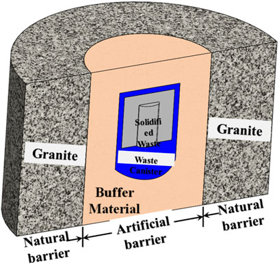
Nuclear waste poses significant risks to both human health and the environment. Safely storing this waste for extended periods has become a major focus of interdisciplinary research, although finding effective solutions remains challenging. Generally, the common approach to nuclear waste disposal is to bury it in geological formations approximately 1000 m underground. The disposal repository adopts a multi-barrier structure (Chen et al., 2014; Hakki and zhan, 2021; Asmaa et al., 2021), as shown in Figure 1. Our country has essentially decided to use Gaomiaozi bentonite as the base material for the buffer material (Li et al., 2022; Xu et al., 2022). Bentonite gradually becomes saturated with groundwater (Yu and Weetjens, 2009). Chemical reactions within the disposal repository generate gases, causing the gas pressure to increase over time, which can significantly impact the stability of the nuclear waste repository (Galle, 2000).
It is widely recognized that the process of gas migration in saturated bentonite occurs in four stages (Xu et al., 2020; Guo et al., 2022; Cui et al., 2022a; Cui et al., 2022b): (i) dissolution and diffusion of gases in bentonite; (ii) two-phase visco-capillary flow in bentonite pores; (iii) gas migration through localized expansion pathways (dilatancy-controlled flow stage); and (iv) macroscopic fracture-controlled flow stage. Understanding the control mechanisms for gas migration (mechanisms ii and iii) is crucial for explaining gas breakthrough. In earlier studies, Graham et al. (2002), Alkan and Müller (2008), Hildenbrand et al. (2010), Hildenbrand et al. (2013), Busch and Amann-Hildenbrand (2013), and Hildenbrand et al. (2015) considered capillary pressure to be the sole controlling factor in the gas migration process and used the traditional two-phase flow theory to study gas breakthrough behavior. Popp et al. (2007); Harrington et al. (2012a); Harrington et al. (2012b), Gerard et al. (2014), Ye et al. (2014), Wsab et al. (2021), and Cui et al. (2021) argued that gas flow could not be controlled solely by capillary pressure and that significant gas flow occurs primarily through pore expansion caused by dilatancy. However, recent studies such as those by Liu et al. (2015), Xu et al. (2015), Xu et al. (2017), Villar et al. (2021), Gutiérrez-Rodrigo et al. (2021), Cui et al. (2022a), and Cui et al. (2022b) have shown that boundary conditions, dry density, and interfaces significantly impact the mechanism of gas migration. They suggested that gas migration is driven by the expansion of the microscopic pathways under flexible boundary conditions, with the dilatancy effect becoming more pronounced as gas injection pressure increases. However, Cui et al. (2022a) and Cui et al. (2022b) believed that both the capillary and dilatancy effects play important roles in gas migration under flexible boundary conditions. Gas injection permeation experiments on bentonite were conducted under rigid boundary conditions (Liu et al., 2015; Xu et al., 2015; Xu et al., 2017; Cui et al., 2022a; Cui et al., 2022b). Xu et al., (2015) and Xu et al. (2017) proposed that gas migration is controlled by a combination of capillary and dilatancy effects at lower dry density, while at higher dry densities, it is primarily controlled by the capillary effect. Cui et al. (2022a) and Cui et al. (2022b) suggested that diffusion and solubility are the mechanisms governing gas migration under rigid boundary conditions. Liu et al. (2015) concluded that gas migration is mainly controlled by the capillary effect and that the preferred gas passage occurs at the interface between the sample and the permeation cylinder. Davy et al. (2009) and Xu et al. (2017) have also investigated the effect of the interface between the cylinder and bentonite on gas migration. They found that gas breakthrough occurred when the gas injection pressure approached the swelling pressure. This indicates that gas flow at the interface between bentonite and the cylinder cannot be neglected when the gas injection pressure approaches or exceeds the swelling pressure.
In recent decades, research has focused on the physical properties of bentonite and the influence of boundary conditions on its permeability and gas breakthrough phenomena. In practice, bentonite is typically used in the form of compacted blocks, which are placed between the waste container and the surrounding rock in the design of high-level radioactive waste repositories, as shown in Figure 2. Inevitably, gaps occur between the bentonite blocks, which may serve as potential conduits for groundwater to enter the disposal repository. After the bentonite blocks expand with water, the gaps gradually heal. The degree of interfacial healing significantly impacts the optimal path of gas migration.
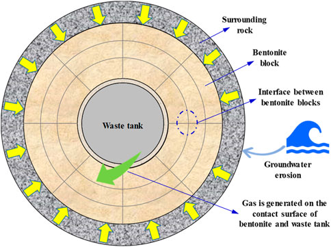
Figure 2. Schematic diagram of gas flow at the interface between bentonite blocks (Guo et al., 2022)
FEBEX bentonite, a Spanish bentonite primarily composed of montmorillonite, was used as a test subject by foreign scholars (Villar et al., 2021; Gutierrez-Rodrigo et al., 2021). They tested gas injection permeability under flexible boundary conditions, both with and without an interface, concluding that the interfaces between bentonites healed after water injection and that these interfaces had little effect on gas migration. Currently, most researchers primarily focus on the mechanism of gas migration in bentonite without an interface, while few investigate the effect of the interfaces between bentonites on gas migration, particularly regarding Gaomiaozi bentonite. Therefore, the exact controlling mechanisms for gas migration in saturated bentonite and the effects of interfaces on gas migration still require further investigation.
In research on gas breakthrough tests for Gaomiaozi bentonite in China, studies have primarily focused on bentonite without an interface, while the permeability of bentonite with an interface has rarely been investigated. In engineering applications, there are primarily two types of boundaries for bentonite buffer structures: 1) the interface between bentonite blocks and 2) the interface between bentonite blocks and the surrounding rock. The influence of surrounding rock stress on the volumetric strain of bentonite is relatively minor, and we simplify the constraints imposed by the surrounding rock on the bentonite as rigid constraints. This paper conducts permeability tests on bentonite under rigid boundary conditions and examines the effects of the interface between bentonite blocks on permeability and the rate of increase in outlet pressure and gas breakthrough pressure. Additionally, the mechanisms by which the interface between bentonite blocks influences gas migration and gas breakthrough are revealed.
2 Test materials and test methods
2.1 Preparation of specimens
In this paper, Gaomiaozi bentonite from Inner Mongolia was selected as the research subject. The water content of the bentonite powder was adjusted to 10.8% using the vapor-phase method (Guo et al., 2022; Ni et al., 2020; Ni et al., 2022). The dry density of bentonite is a critical parameter influencing the sealing performance of disposal repositories. A higher dry density increases the stress exerted on the waste containers, potentially leading to container damage and reduced sealing effectiveness of the repository. Conversely, a lower dry density results in a decreased swelling rate, which reduces the gap-filling capacity between the bentonite and the waste containers, further compromising the sealing performance of the repository. Chen et al. (2016), Xu et al. (2020), Zhang et al. (2012), and Zhang et al. (2014) have recommended that the dry density of bentonite should be controlled within the range of 1.4 g/cm3–1.8 g/cm3. Based on the findings of related research (Guo et al., 2022; Ni et al., 2020; Ni et al., 2022), this paper sets the dry density of bentonite at 1.7 g/cm3.
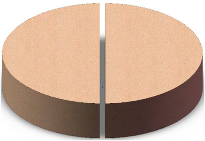
During sample preparation, the bentonite powder was first weighed and then placed into a custom-designed compression mold. It was compacted using an MTS815 testing system under the displacement control mode for 30 min, with a loading rate of 0.1 mm/min (Guo et al., 2022; Ni et al., 2020; Ni et al., 2022). The final samples had a height of 10 mm and a diameter of 50 mm. The prepared samples are shown in Figures 3, 4.
2.2 Test system and test program
2.2.1 Test of swelling pressure
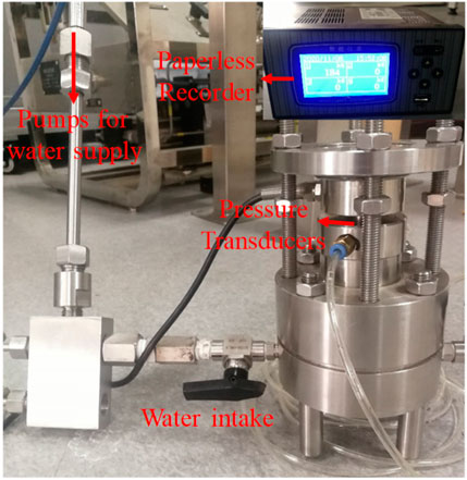
As illustrated in Figure 5, the swelling pressure test of the bentonite sample was conducted in a constant-volume cylindrical cell, with a water injection pressure of 1.0 MPa. A pressure sensor continuously measured the axial force generated during the swelling process of bentonite in real time. The axial force signals were transmitted to a computer via a paperless recorder, and the corresponding software application automatically converted the axial force into the swelling pressure of the sample.
2.2.2 Water-holding characteristic test
The water-holding capacity of the bentonite specimens was determined using the gas phase method. The specific principles of the gas phase method are as follows: bentonite was placed in an evacuated container with a saturated salt solution. The water vapor in the gas allows bentonite to reach the corresponding humidity. When the relative humidity of bentonite equilibrates with that of the specific salt solution environment, the water content of bentonite is measured, indicating its saturation level. Seven saturated solutions were prepared for this test. The relationship between the relative humidity and suction generated by a saturated salt solution can be expressed using the Kelvin–Laplace equation (Ni et al., 2022).
In the formula,
The suction corresponding to different saturated salt solutions can be calculated using Equation 1, as shown in Table 1.
Two samples were tested for water-holding characteristics: one was bentonite without an interface, and the other was bentonite with an interface, both under rigid boundary conditions.
The test steps are as follows: 1) a saturated salt solution is prepared and placed at the bottom of a drying basin; 2) the humidity in the drying basin is measured daily until a specific humidity level is reached; 3) the specimen is placed on a ceramic plate in the center of the drying basin; 4) petroleum jelly is applied to the contact area between the lid and the basin to ensure a proper seal; and 5) the room temperature is maintained at 20°C, and the volume and mass of bentonite are measured periodically until no further changes are observed (Ni et al., 2020; Ni et al., 2022).
2.2.3 Penetration test
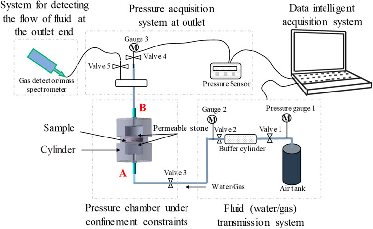
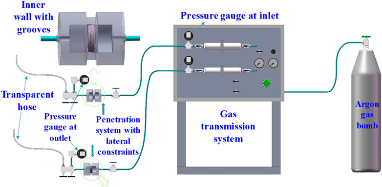
The main features of the seepage test bench under rigid boundary conditions include 1) applying gas injection pressure to the sample; 2) collecting the pressure at the inlet and outlet; and 3) measuring the flow rates of argon and water passing through bentonite. The principle of the permeability test system is shown in Figure 6.
First, the specimen is placed in the cylinder. Argon enters through interface A via the bottom plate, lower indenter, and permeable stone, before flowing into the specimen’s pore space. It then exits through interface B, passing through another permeable stone, the upper indenter, and the aluminum tube. The B end is connected to the tee junction, while the two other ends are connected to pressure gauge 3 and a transparent hose. The pressure at the outlet can be monitored using pressure gauge 3. After collecting the outlet pressure, the transparent hose is connected to the gas detector and mass spectrometer. The mass spectrometer primarily determines the relative content of argon and water after they pass through the sample. Its working principle is as follows: first, the mass spectrometer is evacuated. Then, the pilot sample is evaporated into gaseous molecules, which are bombarded by electron beams to produce positively charged ions. By analyzing the mass-to-charge ratio obtained from the mass spectrometry data, the molecular weight can be determined, allowing for the identification of the sample’s composition. The pressure generated by the molecular impact detector characterizes the content of each component, with higher pressures indicating a greater presence of that component. Since the pressure is measured under vacuum conditions, it is referred to as negative vacuum pressure. The specific steps of the entire testing process are as follows: the specimen is placed inside the cylinder. Next, stop valve 1 was opened to inject argon into the cylinder, and the gas injection pressure was recorded by pressure gauge 1. When the gas injection pressure reaches the set value, cut-off valve 1 is closed. Subsequently, cut-off valves 2 and 3 were opened to inject gas into the specimen, with the pressure in the inlet of the sample monitored by pressure gauge 2. Finally, cut-off valve 4 is closed and cut-off valve 5 is opened to collect the pressure in the outlet. The flow rate of argon and water passing through bentonite was measured using a gas detector and a mass spectrometer. The test system, operating under rigid boundary conditions, is illustrated in Figure 7. Notably, the inner wall of the cylinder features five grooves, each 1.0 mm deep and wide. Bentonite absorbs water and fills these grooves, thereby providing a seal and avoiding gas migration from the interface between the sample and the cylinder (Guo et al., 2022; Ni et al., 2020; Ni et al., 2022).
Bentonite needs to be tested using water injection and gas injection tests under rigid boundary conditions, with the specific process outlined as follows:
2.2.3.1 Water injection test
To eliminate the effect of chemical reactions on the microstructure of the sample, deionized water was used in the water injection test. Additionally, to minimize the disturbance of the water pressure on the microstructure of bentonite, the water pressure injected into bentonite was set at 1.0 MPa, and the water pressure was maintained constant throughout the test. The permeability test was completed once the flow of water stabilized.
2.2.3.2 Gas injection test
Over time, gas will gradually accumulate in the disposal repository. The increase in gas pressure will alter gas flow patterns, accelerating the migration of nuclides through engineered barriers, thereby significantly impacting the stability of the nuclear waste repository. The gas breakthrough pressure of bentonite was tested using a step-by-step gas injection method. This incremental increase in gas pressure closely simulates in situ conditions, allowing for a more accurate estimation of the gas breakthrough pressure in actual projects. Considering the swelling pressure, tensile strength, compressive strength, and size of saturated bentonite, the initial gas injection pressure was set at 1.0 MPa, with a gradient of 1.0 MPa until breakthrough occurred. The gas injection pressure was increased in steps, 1.0 MPa→2 MPa →…pb, using argon as the penetrant.
2.3 Experimental principle
To investigate the mechanisms of gas migration, scholars have defined quantitative indicators that describe the permeability of porous media in the field of nuclear waste disposal. The key indicators for measuring the permeability of bentonite mainly include gas breakthrough pressure pb, gas entry pressure pe, the gas induced-dilatancy pressure pk (Xu et al., 2015; Xu et al., 2017), permeability, increasing the rate of outlet pressure, and the flow rate of argon and water passing through bentonite.
Gas breakthrough (Guo et al., 2022; Guo et al., 2023) is a pulsation phenomenon characterized by fluctuations in gas pressure, accompanied by sudden changes in the microstructure of bentonite. In a step-by-step gas injection test, when the gas pressure in the inlet is less than a certain pressure pb, only a small amount of gas pressure is detected at the outlet. However, when the gas pressure at the inlet exceeds pb, the pressure at the inlet decreases significantly, causing a rapid flow of gas out of the exit. This indicates that a continuous flow path is formed within the sample once gas breakthrough occurs. The critical pressure pb is referred to as the gas breakthrough pressure. The mechanism of gas breakthrough involves capillary cracking, the expansion of pore pathways, and the propagation of the gas–liquid interface. Gas migration in bentonite can be influenced by different mechanisms. If controlled by the capillary effect, gas breakthrough occurs when the gas pressure in the inlet exceeds pe. Alternatively, if gas migration in bentonite was controlled primarily by the dilatancy effect, the effective stress in bentonite causes the pores to rapidly expand and form a connected path when the gas injection pressure reached a certain critical value pk. This critical pressure pk is called the gas-induced dilatancy pressure. Lastly, if the interface effect dominates, gas breakthrough occurs when the gas injection pressure approaches the swelling pressure pz of bentonite.
The increasing rate of outlet pressure is determined by calculating the slope of the fitted pressure growth curve at the exit side. The flow rates of argon and water passing through bentonite are measured using a gas detector and a gas mass spectrometer.
Two commonly used methods for calculating rock permeability are the steady-state and transient methods. The steady-state method is used to determine the steady-state value of seepage velocity in a rock sample under a constant pressure gradient. In contrast, the transient method is used to determine the time series of the permeability pressure difference across both ends of a rock sample. The pressures at both ends of the sample are called the inlet and outlet pressures. Many scholars use this method to calculate the permeability of low-permeability samples (Liu et al., 2019; Guo et al., 2022). The following section mainly discusses the method for calculating permeability. According to Darcy’s law, the flow rate of argon across the cross section of the sample can be calculated by Equation 2.
where
According to Equation 2, the seepage velocity of argon on the cross section of the sample can be calculated by Equation 3.
The equation of state for gas migration in bentonite can be expressed as follows:
where
Considering that the flow of argon in the sample is one-dimensional seepage, the mass of argon in the microelement of length
Here,
Taking the material derivative (Wu et al., 2020; Wu et al., 2022; Wu et al., 2024) of Equation 5, Equation 6 can be obtained.
According to the Dupuit–Forchheimer kinematic relationship, the permeation velocity of gas in bentonite is
where the material derivative of the volume element
Substituting Equations 7 and 8 into Equation 6, Equation 9 can be obtained.
According to the law of conservation of mass (Shi et al., 2023a; Shi et al., 2023b; Shi et al., 2023c), it is known that
Substituting Equation 10 into Equation 9 and taking into account that
Substituting Equation 3 into Equation 11, Equation 12 can be obtained.
For steady seepage, Equation 12 can be simplified as
If bentonite is homogeneous, the permeability of bentonite does not vary with the location of the section, and Equation 13 can be further simplified as
The height of the sample is
Integrating Equation 14 and taking into account the boundary condition
where
According to the boundary condition
Substituting Equation 18 into Equation 17, Equation 19 can be obtained.
or
Substituting Equation 20 into Equation 2, Equation 21 can be obtained.
The flow rate of argon through bentonite is too low to be measured accurately. Therefore, Equation 21 cannot be used to calculate the permeability of bentonite (Guo et al., 2023).
The pressure at the inlet decreases over time, but the decrease is minimal. According to Equation 4, the mass of argon flowing into the pores of the sample per unit time is expressed by Equation 22:
where
In time
Substituting Equation 24 into Equation 23, Equation 25 can be obtained.
Substituting Equation 25 into Equation 21, Equation 26 can be obtained.
Considering that permeability is constant at different locations of the section and taking
3 Test results
3.1 Swelling properties of bentonite
Figure 8 shows the change curves of the swelling pressure over time during water injection saturation for both bentonite without an interface and bentonite with an interface.
As shown in Figure 8, the swelling pressure increases rapidly at first, then decreases at a slower rate after reaching the peak value, and finally stabilizes at a gradual rate. The cations within montmorillonite crystals chemically react with water, causing the distance between the crystals to increase (Arcos et al., 2003; Zhao et al., 2018; Bian et al., 2019; Sun et al., 2019). As a result, bentonite swells when it absorbs water. Under rigid boundary conditions, the deformation of bentonite is constrained, generating a “wedge” force between the crystals. This accumulation of this “wedge” force is manifested as swelling pressure. When the moisture content reaches a certain level, the pores between the bentonite crystals slightly collapse, leading to a decrease in swelling pressure. As water injection continues, the collapsed crystals reabsorb water again, causing the swelling pressure to increase once more. Consequently, the swelling pressure evolution curve generally exhibits a bimodal pattern.
The swelling pressure of bentonite without an interface and bentonite with an interface, when they tend to become saturated, were 3.62 MPa and 3.17 MPa, respectively. Due to the interface between bentonite crystals, bentonite with an interface has relatively free expansion space in the initial stage, resulting in a lower degree of accumulation of “wedge” force. In contrast, bentonite without an interface lacks this free expansion space, leading to a higher swelling pressure.
3.2 Water holding characteristic of bentonite
The corresponding suction force and saturation of bentonite under different saturated salt solutions are shown in Table 2.
For small-sized specimens, the critical value of capillary pressure is approximately equal to the gas entry pressure. Based on the soil–water characteristic curve, the gas entry pressure can be calculated using the van Genuchten model. The specific expression for the van Genuchten model (Genuchten, 1980) is given by
where
The gas entry pressure and parameter
3.3 Penetration test results
Water injection and gas injection tests on bentonite without an interface and bentonite with an interface under rigid boundary conditions were conducted. Table 3 shows the parameters of the two samples.
3.3.1 Water retention tests
The curve showing the water volume injected into bentonite without an interface and bentonite with an interface under rigid boundary conditions is shown in Figure 9.
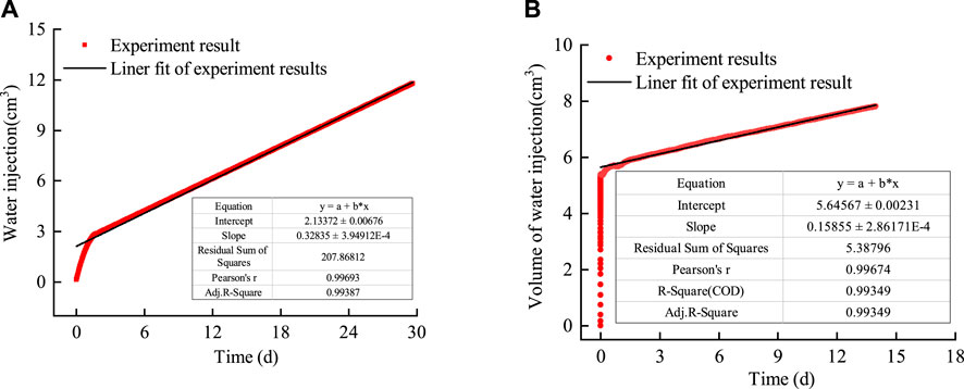
Figure 9. Variation curve of the water volume injected into bentonite with time. (A) Bentonite without an interface. (B) Bentonite with an interface.
1) As shown in Figure 9A, the volume of water injected into bentonite without an interface increased sharply with time during the initial stage, while it stabilized after approximately 2 days. This indicates that bentonite without an interface shifted from unsaturated permeability to saturated permeability. Similar experimental results were reported by Guo et al. (2022) in their water injection experiments on bentonite under flexible boundary conditions. The permeability during the water injection stage can be calculated as 2.02 × 10⁻²⁰ m2 using Darcy’s law. 2) As shown in Figure 9B, the volume of water injected into bentonite with an interface increased sharply with time during the initial stage and then tended to stabilize along a straight line after approximately 1 day. The permeability during the water injection stage, calculated as 1.12 × 10⁻²⁰ m2 using Darcy’s law, did not differ significantly from that of bentonite without an interface. This indicates that the interface between the bentonite heals after encountering water.
3.3.2 Gas breakthrough tests
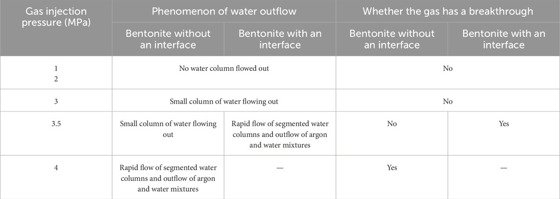
The comparative curves of inlet and outlet pressures for two samples at gas injection pressures of 1.0 MPa, 2.0 MPa, 3.0 MPa, 3.5 MPa, and 4.0 MPa are shown in Figure 10.
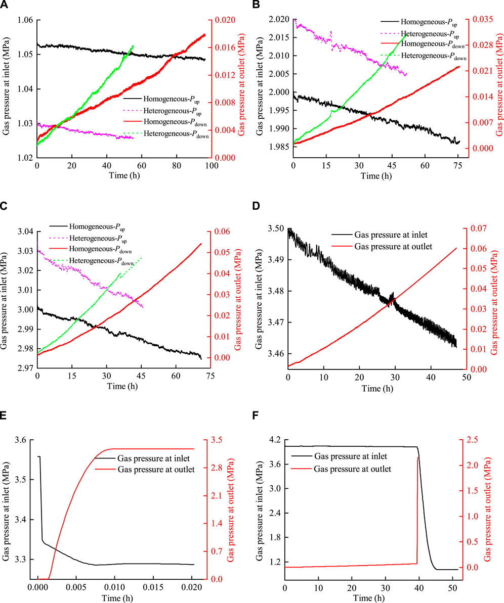
Figure 10. Comparison curve between inlet and outlet pressures for two samples. (A) Pup = 1.0 MPa, (B) Pup = 2.0 MPa, (C) Pup = 3.0 MPa, (D) Pup = 3.5 MPa (bentonite without an interface), (E) Pup = 3.5 MPa (bentonite with an interface), and (F) Pup = 4.0 MPa.
The curves in Figure 10 showed that 1) the decrease in inlet pressure and the increase in outlet pressure vary linearly during the gas injection stage of 1.0 MPa, 2.0 MPa, and 3.0 MPa. Throughout the testing period, the outlet pressure of the two samples increased to a maximum of 0.055 MPa, which was significantly different from the inlet pressure. This observation suggests that the pore expansion within bentonite was minimal during the gas injection process, indicating that gas migration was primarily influenced by dissolution, diffusion, or two-phase flow. 2) When the gas injection pressure was 3.5 MPa, the outlet pressure of bentonite without an interface increased to a maximum of 0.06 MPa, with no gas breakthrough occurring. In contrast, for bentonite with an interface, the inlet pressure decreased sharply, while the outlet pressure increased dramatically within a few minutes. Subsequently, the pressures at the inlet and outlet reached equilibrium in a very short time. This indicated that a continuous flow channel was formed at this stage, leading to gas breakthrough. 3) In the gas injection stage at 4.0 MPa, a sharp increase in outlet pressure was observed, while the inlet pressure experienced a significant decrease at approximately 40 h into the process. Subsequently, the pressure in the inlet and outlet of bentonite without an interface reached a state of equilibrium. It indicated that gas breakthrough occurred during this gas injection stage. However, foreign scholars (Villar et al., 2021; Gutiérrez-Rodrigo et al., 2021) believed that the interfaces between bentonites healed, suggesting that the interface had little effect on gas migration after saturation with water injection.
The flow rate of argon through bentonite without an interface and bentonite with an interface at different injection pressures and time intervals are shown in Tables 4, 5, respectively. The experimental results are shown in Table 6.
As illustrated in Tables 4–6, the flow rates of argon and water under gas injection pressure through bentonite with an interface and bentonite without an interface are similar. 1) At injection pressures of 1.0 MPa and 2.0 MPa, the flow rates of argon for both samples are higher during the initial phase and at the 5-min mark; however, these rates decrease after half an hour (see Tables 4, 5). Notably, there is no outflow of the water column during injection (see Table 6). This observation suggests that diffusion and solubility are the primary mechanisms controlling gas migration at this stage. As surface tension increases with decreasing pore size, insufficient gas pressure to counteract capillary pressures within the pores leads to gas dissolving or diffusing in the water. Previous studies have reached similar conclusions (Liu et al., 2015; Xu et al., 2015; Cui et al., 2022a). 2) With an increase in gas injection pressure, the flow rates of argon through both samples also increased (see Tables 4, 5), accompanied by a small outflow of the water column. As gas injection pressure increased, the solubility of gas in bentonite also increased. When the pore pressure reaches a certain threshold, some water is driven out of the sample, indicating that the two-phase visco-capillary flow in bentonite pores is the primary mechanism at play. 3) When the gas injection pressure reaches 3.5 MPa, the flow rate of argon through bentonite with an interface increases by two orders of magnitude (see Table 5), and the relative flow rate of argon increases sharply. Additionally, numerous small water columns flow rapidly through the clear tubes, resulting in a mixture of water and argon being expelled (see Table 6). This observation suggests that connected seepage paths form within bentonite during this gas injection phase, indicating that gas breakthrough occurs. In contrast, gas breakthrough in bentonite without an interface does not occur until the gas injection pressure reaches 4.0 MPa. This finding suggests that the gas breakthrough pressure of bentonite with an interface is lower and that the interface between bentonite blocks can heal while still influencing gas migration.
The pressure measured by the gas detector holds no practical significance and solely represents the relative flow rates of argon and water through bentonite. The relative flow rates of argon and water through the two samples are illustrated in Figures 11, 12.
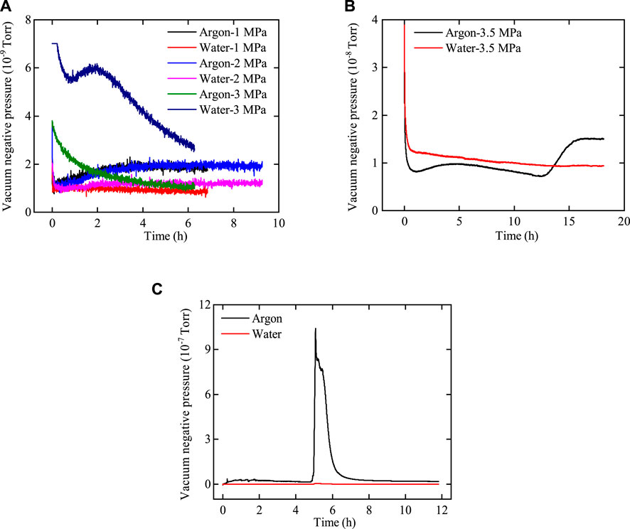
Figure 11. Variation curve of the vacuum negative pressure of argon and water with time after passing through bentonite without an interface. (A) Pup = 1.0 MPa–3.0 MPa, (B) Pup = 3.5 MPa, and (C) Pup = 4.0 MPa.
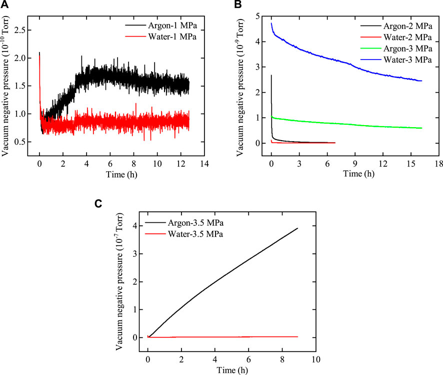
Figure 12. Variation curve of the vacuum negative pressure of argon and water with time after passing through bentonite with an interface. (A) Pup = 1.0 MPa, (B) Pup = 2.0 MPa–3.0 MPa, and (C) Pup = 3.5 MPa.
As shown in Figures 11, 12, the variations in the flow rates of argon and water with injection pressure through bentonite with and without an interface are similar. 1) At low gas injection pressure, the flow rate of argon through bentonite exceeds that of water, with both flow rates remaining very low. 2) As gas pressure increases, the flow rate of water through bentonite gradually surpasses that of argon, confirming that the influence of two-phase viscous-capillary flow effects increases. 3) At a gas injection pressure of 3.5 MPa, the flow rates of argon and water through interfacial bentonite are significantly greater than those through bentonite without an interface. The phenomenon occurs because gas breakthrough in interfacial bentonite happens at 3.5 MPa, while gas breakthrough in bentonite without an interface does not occur until the pressure reaches 4.0 MPa. This indicates that the interface between bentonite can heal after water injection, although it may weaken the mechanical properties of bentonite.
3.4 Effect of the interface between bentonite blocks on permeability parameters
Based on the test results and the principles for calculating permeability and the rate of increase in outlet pressure, as described in the experimental principles section, the permeability and rate of increase in outlet pressure at different gas injection pressures are presented in Table 7.
As is well known, there is a strong coupling relationship between swelling pressure and gas injection pressure during the gas migration process in bentonite. Thus, the swelling pressure and gas injection pressure are the primary factors affecting the permeability of bentonite. As shown in Table 7. 1) at gas injection pressures of 1.0 MPa, 2.0 MPa, and 3.0 MPa, the permeability of both samples is on the order of 10–21 m2. The permeability and rate of increase in outlet pressure for the two samples show an increasing trend with increasing gas injection pressure. Liu et al. (2014) and Liu et al. (2015) reached a similar conclusion. As the gas injection pressure increases, it drives water out, facilitating its passage through bentonite. 2) The gas breakthrough pressure for bentonite without an interface is 4.0 MPa, while that for bentonite with an interface is 3.5 MPa. During the gas breakthrough stage, the permeability and rate of increase in outlet pressure are several orders of magnitude greater than in the non-breakthrough stage. This is attributed to the formation of continuous seepage paths within bentonite, resulting in a sharp increase in permeability and outlet pressure.
To investigate the effect of the interface between bentonite blocks on permeability under rigid boundary conditions, the permeability and rate of increase in outlet pressure for bentonite without an interface and bentonite with an interface are compared, as shown in Figure 13. A significant difference is observed in both permeability and the rate of increase in outlet pressure between the breakthrough and non-breakthrough stages. The logarithmic method is employed to describe the coordinate axes, facilitating the comparison of the variations in permeability and the rate of increase in outlet pressure between these two stages.
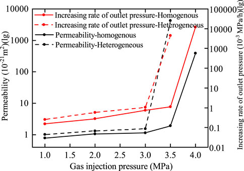
Figure 13. Comparative curves of permeability parameters for bentonites with and without an interface.
The curves presented in Figure 13 indicate that 1) at the same gas injection pressure, the permeability and rate of increase in outlet pressure for bentonite with an interface are greater than those for bentonite without an interface. Guo et al. (2022) reached a similar conclusion under flexible boundary conditions. 2) The gas breakthrough pressure for bentonite without an interface is 4.0 MPa, while the gas breakthrough pressure for bentonite with an interface is 3.5 MPa. Under rigid boundary conditions, the radial displacement of bentonite is constrained. The normal radial stress of bentonite decreases after water loss and increases upon water absorption. Furthermore, the swelling pressure of bentonite without an interface is greater than that of bentonite with an interface. Consequently, the permeability and rate of increase in outlet pressure for bentonite with an interface are greater, while the gas breakthrough pressure is lower.
4 Mechanism of gas migration and gas breakthrough in saturated bentonite
According to the gas equation of state, substituting Equation 4 into Equation 29, we obtain
Expanding the left side of Equation 30, we obtain
According to the theory of continuum mechanics, the material derivative of the bentonite volume element is
where
Considering that the particle velocity of bentonite is very small, the material derivative
Substituting Equation 33 into Equation 31, we obtain
Under rigid boundary conditions, the bentonite specimen is squeezed by the cylinder with minimal changes in radial and axial strain rates. In addition, the geometry and stress conditions of the specimen are axisymmetric, and the circumferential strain rate is 0. Therefore, the volume fraction of bentonite remains constant. Consequently, Equation 34 can be simplified as
Since the pore volume is the product of porosity and the micro-element volume, the strain rate of the pore volume is of the same order of magnitude as that of the micro-element volume. It can be assumed that the pore variation in bentonite is minimal under rigid boundary conditions. Consequently, Equation 35 can be further simplified as
As seen from Equation 36, the pressure in the pores of bentonite increases continuously with the continuous injection of gas. The increase in pore pressure leads to the escape of water. Therefore, there is a water–gas two-phase flow in the bentonite specimen under rigid boundary conditions.
Under rigid boundary conditions, the interface between the bentonites has a slight effect on the gas breakthrough pressure; however, the mechanism of gas breakthrough remains the same. In the following analysis, we analyze the mechanism of gas breakthrough under rigid boundary conditions based on the experimental results of bentonite with and without an interface.
The gas breakthrough pressure, swelling pressure, and gas entry pressure of bentonite with and without an interface are shown in Figures 14A, B.
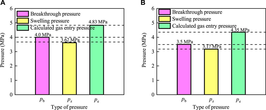
Figure 14. Comparison of gas breakthrough pressure, swelling pressure, and gas entry pressure for bentonite with and without an interface. (A) Bentonite without an interface. (B) Bentonite with an interface.
The curves presented in Figure 14A indicate that the gas breakthrough pressure (
The results of the tests indicate that the gas breakthrough pressure is greater than the swelling pressure but less than the gas entry pressure. This suggests that the gas pressure is insufficient to cause capillary rupture at the time of gas breakthrough, which facilitates the passage of gas through the cylinder and bentonite interface. In other words, the optimal pathway for gas breakthrough under rigid boundary conditions is the interface between the cylinder and bentonite (Xu et al., 2015; Liu et al., 2014; Liu et al., 2015).
In the permeation test of bentonite, several phenomena were observed. By analyzing these phenomena, we describe the mechanisms of gas migration and breakthrough in saturated bentonite.
(1) Saturated bentonite contains pores of varying sizes, and the surface tension at the gas–water interface impedes gas flow. Surface tension increases as pore size decreases. When the gas pressure is insufficient to counteract the capillary forces within the pores, the gas is limited to dissolving or diffusing in the water.
(2) As gas injection pressure increases, the solubility of a gas in bentonite also increases. When the pore pressure reaches a certain threshold, water is expelled from the sample, leading to desaturation. This results in a reduction in the swelling pressure, a weakening of hydraulic properties, and a decrease in the effective stress applied. When the gas injection pressure approaches or exceeds the expansion pressure of the bentonite, the interface between bentonite and the cylinder is forced open, creating a continuous flow path.
5 Conclusion
The study of gas migration mechanisms in saturated bentonite is critical to the safety of disposal repositories and has profound implications for the sustainable development of nuclear energy. Based on this, numerous scholars have conducted extensive research on factors such as boundary conditions, dry density, and temperature (Liu et al., 2015; Xu et al., 2015; Xu et al. 2017; Xu et al. 2020; Cui et al., 2022a; Cui et al. 2022b; Cui et al. 2024a). Unfortunately, most of these studies have overlooked the influence of interfaces within bentonite, treating it as a homogeneous material. However, recent research has shown that interfaces within bentonite significantly affect gas migration pathways (Guo et al., 2022; Cui et al., 2024b). To further investigate the role of interfaces in gas migration mechanisms, this study conducted water injection tests, water retention tests, and gas breakthrough tests on both interface-free and interface-containing bentonite samples. The effects of interface conditions on parameters such as the permeability of saturated bentonite, the rate of increase in outlet pressure, and gas breakthrough pressure were analyzed. The results revealed the mechanisms of capillary rupture, pore expansion, and interface effects during gas breakthrough. The main conclusions are as follows:
(1) At low gas injection pressures, diffusion and solubility are the primary mechanisms controlling gas migration. Saturated bentonite contains pores of varying sizes, and the surface tension at the gas–water interface hinders gas flow. Surface tension increases as pore size decreases. When the gas pressure is insufficient to counteract the capillary forces within the pores, the gas can only dissolve or diffuse in water.
(2) As gas pressure increases, permeability, the rate of increase in outlet pressure, and the flow rate of argon through both samples also increase, accompanied by a slight outflow of the water column. With increasing gas injection pressure, the solubility of gas in bentonite increases. When the pore pressure reaches a certain threshold, some water is driven out of the sample, resulting in desaturation. This leads to a reduction in the swelling pressure of the soil, a weakening of its hydraulic properties, and a decrease in the effective stress applied. These changes indicate that the two-phase visco-capillary flow within the bentonite pores becomes the dominant mechanism as the gas injection pressure increases.
(3) The swelling pressure, gas entry pressure, and gas breakthrough pressure of bentonite without an interface were greater than those of bentonite with an interface. This indicates that while bentonite with an interface healed after water injection, it affected the mechanical properties of bentonite, reducing the soil’s strength.
(4) The swelling pressure, gas entry pressure, and gas breakthrough pressure of bentonite without an interface were 3.17 MPa, 4.35 MPa, and 3.5 MPa, respectively, while those of bentonite with an interface were 3.62 MPa, 4.83 MPa, and 4.0 MPa. By comparing the gas breakthrough pressure, swelling pressure, and gas entry pressure of the two specimens, it was found that the gas breakthrough pressure was greater than the swelling pressure but less than the gas entry pressure. This indicates that the gas pressure was insufficient to cause a capillary rupture during gas breakthrough, allowing gas to pass more easily through the interface between the cylinder and bentonite.
This paper primarily investigates the influence of interfaces on gas migration mechanisms and the role of gas breakthrough, providing valuable insights for developing safety strategies in disposal repositories. However, gas migration and breakthrough in bentonite are complex phenomena influenced by multiple factors. Without a clear understanding of the coupling relationships among these factors, it will be challenging to make accurate assessments of repository safety, which, in turn, could hinder the sustainable development of nuclear energy. In future work, this study will continue to explore the complex interactions of factors such as boundary conditions, dry density, temperature, and interfaces in the gas migration process through bentonite gas breakthrough experiments. A coupled fluid–solid model will be developed to better understand the gas migration mechanisms under the influence of multi-factors.
Data availability statement
The datasets presented in this study can be found in online repositories. The names of the repository/repositories and accession number(s) can be found in the article/supplementary material.
Author contributions
DL: conceptualization, methodology, software, writing–original draft, and writing–review and editing. JG: data curation, supervision, validation, and writing–review and editing. QL: conceptualization, resources, validation, and writing–review and editing. ZC: conceptualization, methodology, resources, validation, and writing–review and editing.
Funding
The author(s) declare that financial support was received for the research, authorship, and/or publication of this article. The authors are grateful to the support of the Scientific Research Foundation of CUIT (No. KYTZ2022142), the Sichuan National Applied Mathematics Center—Chengdu University of Information Technology, the Institute of Applied Mathematics for Intelligent Systems (No. 2023ZX001), and the college students’ innovation special project funded by the Chengdu University of Information Technology (No. 202410621322).
Conflict of interest
The authors declare that the research was conducted in the absence of any commercial or financial relationships that could be construed as a potential conflict of interest.
Publisher’s note
All claims expressed in this article are solely those of the authors and do not necessarily represent those of their affiliated organizations, or those of the publisher, the editors and the reviewers. Any product that may be evaluated in this article, or claim that may be made by its manufacturer, is not guaranteed or endorsed by the publisher.
References
Alkan, H., and Müller, W. (2008). Approaches for modelling gas flow in clay formations as repository systems. Phys. Chem. Earth, Parts A/B/C. 33, 260–268. doi:10.1016/j.pce.2008.10.037
Arcos, D., Bruno, J., and Karnland, O. (2003). Geochemical model of the granite-bentonite-groundwater interaction at aspo HRL (LOT experiment). Appl. Clay Sci. 23, 219–228. doi:10.1016/S0169-1317(03)00106-6
Asmaa, S., Mamadou, F., Christian, D., and Mohammed, A. (2021). Effect of groundwater chemistry and temperature on swelling and microstructural properties of sand–bentonite for barriers of radioactive waste repositories. Bull. Eng. Geol. Environ. 80, 1857–1873. doi:10.1007/s10064-020-02020-5
Bian, X., Cui, Y.-J., Zeng, L.-L., and Li, X.-Z. (2019). Swelling behavior of compacted bentonite with the presence of rock fracture. Eng. Geol. 254, 25–33. doi:10.1016/j.enggeo.2019.04.004
Busch, A., and Amann-Hildenbrand, A. (2013). Predicting capillarity of mudrocks. Mar. petroleum Geol. 45, 208–223. doi:10.1016/j.marpetgeo.2013.05.005
Chen, L., Liu, Y.-M., Wang, J., Cao, S.-F., Xie, J.-L., Ma, L.-K., et al. (2014). Investigation of the thermal-hydro-mechanical (THM) behavior of GMZ bentonite in the China-Mock-up test. Eng. Geol. 172, 57–68. doi:10.1016/j.enggeo.2014.01.008
Chen, Y.-G., Jia, L.-Y., Niu, L.-H., Ye, W.-M., Chen, B., and Cui, Y.-J. (2016). Effect of dry density and pH on the diffusion behavior of lanthanum in compacted Chinese GMZ bentonite. J. Radioanalytical Nucl. Chem. 310, 1303–1310. doi:10.1007/s10967-016-4972-5
Cui, L.-Y., Masum, S.-A., Ye, W.-M., and Thomas, H.-R. (2022a). Investigation on gas migration behaviours in saturated compacted bentonite under rigid boundary conditions. Acta Geotech. 17 (6), 2517–2531. doi:10.1007/s11440-021-01424-1
Cui, L. Y., Masum, S. A., Ye, W. M., Thomas, H. R., Zhou, C., and Hu, H. Q. (2024a). Numerical investigation of gas migration behaviour in saturated bentonite with consideration of temperature. Acta Geotech. 19 (5), 2381–2393. doi:10.1007/s11440-024-02272-5
Cui, L.-Y., Ye, W.-M., Wang, Q., Chen, Y.-G., and Chen, B. (2022b). Gas migration behavior in saturated bentonite under flexible conditions with consideration of temperature effects. Acta Geotech. 18, 971–984. doi:10.1007/s11440-022-01624-3
Cui, L. Y., Ye, W. M., Wang, Q., Chen, Y. G., and Cui, Y. J. (2024b). Investigation on successive gas breakthroughs behavior of saturated GMZ bentonite under rigid boundary conditions. Acta Geotech. 19 (10), 6773–6786. doi:10.1007/s11440-024-02391-z
Cui, L.-yong., Ye, W.-M., Wang, Q., Chen., Y.-G., Chen, B., and Cui, Y.-J. (2021). Insights into gas migration behavior in saturated GMZ bentonite under flexible constraint conditions. Constr. Build. Mater. 287, 123070. doi:10.1016/j.conbuildmat.2021.123070
Davy, C.-A., Skoczylas, F., Lebon, P., and Dubois, T. (2009). Gas migration properties through A bentonite/argillite interface. Appl. Clay Sci. 42, 639–648. doi:10.1016/j.clay.2008.05.005
Galle, C. (2000). Gas breakthrough pressure in compacted Fo–Ca clay and interfacial gas overpressure in waste disposal context. Appl. clay Sci. 17, 85–97. doi:10.1016/S0169-1317(00)00007-7
Genuchten, V. (1980). A closed-form equation for predicting the hydraulic conductivity of unsaturated soils. Soil Sci. Soc. Am. J. 44, 892–898. doi:10.2136/sssaj1980.03615995004400050002x
Gerard, P., Harrington, J., Charlier, R., and Collin, F. (2014). Modelling of localised gas preferential pathways in claystone. Int. J. Rock Mech. Min. Sci. 67, 104–114. doi:10.1016/j.ijrmms.2014.01.009
Graham, J., Halayko., K.-G., Hume., H., Kirkham, T., Gray, M., and Oscarson, D. (2002). A capillary-advective model for gas break-through in clays. Eng. Geol. 64, 273–286. doi:10.1016/S0013-7952(01)00106-5
Guo, J.-N., Liu, J.-F., Zhang, Q., Cao, S.-F., and Chen, Z.-Q. (2022). Gas migration properties through saturated bentonite considering the interface effect. Geomechanics Geophys. Geo-Energy Geo-Resources 8 (2), 66. doi:10.1007/s40948-022-00370-w
Guo, J.-N., Zhang, Q., Chen., L., Cao, S.-F., Xie, J.-L., Li, Q., et al. (2023). A coupled fluid-mechanical interaction model for controlled gas migration mechanism by dilatancy effect in saturated bentonite. Geomechanics Geophys. Geo-Energy Geo-Resources 9 (1), 119. doi:10.1007/s40948-023-00647-8
Gutiérrez-Rodrigo, V., Martín, P.-L., and Villar, M.-V. (2021). Effect of interfaces on gas breaktrough pressure in compacted bentonite used as engineered barrier for radioactive waste disposal. Process Saf. Environ. Prot. 149, 244–257. doi:10.1016/j.psep.2020.10.053
Hakki, O., and zhan, O. (2021). Determination of mechanical and hydraulic properties of polyacrylamide-added bentonite-sand mixtures. Bull. Eng. Geol. Environ. 80, 2557–2571. doi:10.1007/s10064-020-02062-9
Harrington, J.-F., Milodowski., A.-E., Graham, C.-C., Rushton, J.-C., and Cuss, R.-J. (2012a). Evidence for gas-induced pathways in clay using a nanoparticle injection technique. Mineral. Mag. 76, 3327–3336. doi:10.1180/minmag.2012.076.8.45
Harrington, J.-F., Vaissière, R., Noy, D.-J., Cuss, R.-J., and Talandier, J. (2012b). Gas flow in Callovo-Oxfordian claystone (COx): results from laboratory and field-scale measurements. Mineral. Mag. 76, 3303–3318. doi:10.1180/minmag.2012.076.8.43
Hildenbrand, A., Bertier, P., Busch, A., and Krooss, B.-M. (2013). Experimental investigation of the sealing capacity of generic clay-rich caprocks. Int. J. Greenh. Gas Control 19, 620–641. doi:10.1016/j.ijggc.2013.01.040
Hildenbrand, A., Krooss, B.-M., Bertier, P., and Busch, A. (2015). Laboratory testing procedures for CO2 capillary entry pressures on caprocks. Carbon Dioxide Capture Storage Deep Geol. Form. 4, 383–412.
Hildenbrand, A., Schlömer, S., and Krooss, B.-M. (2010). Gas breakthrough experiments on fine-grained sedimentary rocks. Geofluids 2, 3–23. doi:10.1046/j.1468-8123.2002.00031.x
Li, H., Tan, Y.-Z., Xie, Z.-Y., and Sun, D. (2022). Effect of hydrothermal path on swelling pressure and hydraulic conductivity of compacted bentonite. Bull. Eng. Geol. Environ. 81, 479. doi:10.1007/s10064-022-02972-w
Liu, J.-F., Davy, C.-A., Talandier, J., and Skoczylas, F. (2014). Effect of gas pressure on the sealing efficiency of compacted bentonite–sand plugs. J. Contam. Hydrology 170, 10–27. doi:10.1016/j.jconhyd.2014.09.006
Liu, J.-F., Song, S.-B., Cao, X.-L., Meng., Q.-B., Pu, H., Wang, Y.-G., et al. (2019). Determination of full-scale pore size distribution of Gaomiaozi bentonite and its permeability prediction. J. Rock Mech. Geotechnical Eng. 12 (2), 403–413. doi:10.1016/j.jrmge.2019.12.005
Liu, J. F., Song, Y., Skoczylas, F., and Liu, J. (2015). Gas migration through water-saturated bentonite-sand mixtures, Cox argillite, and their interfaces. Can. Geotechnical J. 52, 60–71. doi:10.1139/cgj-2014-0412
Ni, H.-Y., Liu, J.-F., Guo., J.-N., Yang, D.-S., and Chen, Y.-G. (2020). Numerical modelling on water retention and permeability of compacted GMZ bentonite under free-swelling conditions. Int. J. Numer. Anal. Methods Geomechanics 44, 1619–1633. doi:10.1002/nag.3078
Ni, H. Y. J.-F. L., Zhang, Q., Ma, L.-K., Guo, J.-N., and Mao, X.-B. (2022). Water retention behavior and double porosity model study of GMZ bentonite considering temperature effects. Eng. Geol. 304, 1–13. doi:10.1016/j.enggeo.2022.106695
Popp, T., Wiedemann, M., Bohnel, H., Minkley, W., and Manthei, G. (2007). Untersuchungen zur Barriereintegrität im Hinblick auf das Ein-Endlager-Konzept. Leipzig, Germany: Insitut fur Gebirgsmechanik GmbH.
Shi, H., Chen, W., Zhang, H., and Lei, S. (2023b). A novel obtaining method and mesoscopic mechanism of pseudo-shear strength parameter evolution of sandstone. Environ. Earth Sci. 82, 60. doi:10.1007/s12665-023-10748-y
Shi, H., Chen, W., Zhang, H., Song, L., Ming, L., Wang, M., et al. (2023a). Dynamic strength characteristics of fractured rock mass. Eng. Fract. Mech. 292, 109678. doi:10.1016/j.engfracmech.2023.109678
Shi, H., Zhang, H., Chen, W., Song, L., and Li, M. (2023c). Pull-out debonding characteristics of rockbolt with prefabricated cracks in rock: a numerical study based on particle flow code. Comput. Part. Mech. 11, 29–53. doi:10.1007/s40571-023-00607-9
Sun, Z., Chen, Y., Cui, Y.-J., Ye, W.-M., and Chen, B. (2019). Effect of synthetic Beishan site water and cement solutions on the mineralogy and microstructure of compacted Gaomiaozi(GMZ) bentonite. Soils Found. -Tokyo- 59 (6), 2056–2069. doi:10.1016/j.sandf.2019.11.006
Villar, M.-V., Carbonell, B., Martín, P.-L., and Gutierrez-Alvarez, C. (2021). The role of interfaces in the bentonite barrier of a nuclear waste repository on gas transport. Eng. Geol. 286 (1), 106087. doi:10.1016/j.enggeo.2021.106087
Wsab, C., Cheng, L.-D., Yang., D.-C., and Sun, D. (2021). Evaluation of hydro-mechano-chemical behaviour of bentonite-sand mixtures. J. Rock Mech. Geotechnical Eng. 14, 637–652. doi:10.1016/j.jrmge.2021.10.008
Wu, J. Y., Jing, H. W., Gao, Y., Meng, Q. B., Yin, Q., and Du, Y. (2022). Effects of carbon nanotube dosage and aggregate size distribution on mechanical property and microstructure of cemented rockfill. Cem. Concr. Compos. 127, 104408. doi:10.1016/j.cemconcomp.2022.104408
Wu, J. Y., Jing, H. W., Yin, Q., Yu, L. Y., Meng, Q. B., and Li, S. C. (2020). Strength prediction model considering material, ultrasonic and stress of cemented waste rock backfill for recycling gangue. J. Clean. Prod. 276, 123189. doi:10.1016/j.jclepro.2020.123189
Wu, J. Y., Wong, H. S., Zhang, H., Yin, Q., Jing, H. W., and Ma, D. (2024). Improvement of cemented rockfill by premixing low-alkalinity activator and fly ash for recycling gangue and partially replacing cement. Cem. Concr. Compos. 145, 105345. doi:10.1016/j.cemconcomp.2023.105345
Xu, L., Ye, W.-M., Chen, Y.-G., Chen, B., and Cui, Y.-J. (2020). Investigation on gas permeability of compacted GMZ bentonite with consideration of variations in liquid saturation, dry density and confining pressure. J. Contam. Hydrology 230, 103622. doi:10.1016/j.jconhyd.2020.103622
Xu, L., Ye, W.-M., and Ye, B. (2017). Gas breakthrough in saturated compacted GaoMiaoZi (GMZ) bentonite under rigid boundary conditions. Can. Geotechnical J. 54, 1139–1149. doi:10.1139/cgj-2016-0220
Xu, L., Ye, W.-M., Ye, B., Chen., B., Chen, Y.-G., and Cui, Y.-J. (2015). Investigation on gas migration in saturated materials with low permeability. Eng. Geol. 197, 94–102. doi:10.1016/j.enggeo.2015.08.019
Xu, L.-B., Ye, W.-M., Liu, Z.-R., Wang, Q., and Chen, Y.-G. (2022). Investigation on intrusion of bentonite–sand mixtures in fractures with consideration of sand content and seepage effects. Bull. Eng. Geol. Environ. 81, 70. doi:10.1007/s10064-021-02559-x
Ye, W. M., Xu., L., Chen, B., Chen, Y.-G., Ye, B., and Cui, Y.-J. (2014). An approach based on two-phase flow phenomenon for modeling gas migration in saturated compacted bentonite. Eng. Geol. 169, 124–132. doi:10.1016/j.enggeo.2013.12.001
Yu, L., and Weetjens, E. (2009). Summary of gas generation and migration. Mol, Belgium: SCK† CEN. Current State-of-the-Art. SCK-CEN ER-106.
Zhang, H.-Y., Cui, S.-L., Zhang, M., and Jia, L.-Y. (2012). Swelling behaviors of GMZ bentonite–sand mixtures inundated in NaCl–Na2SO4 solutions. Nucl. Eng. Des. 242, 115–123. doi:10.1016/j.nucengdes.2011.10.042
Zhang, M., Zhang, H.-Y., Zhou., L., Wang, B.-M., and Wang, S.-J. (2014). Hydro-mechanical analysis of GMZ bentonite-sand mixtures in the water infiltration process as the buffer/backfill mixture in an engineered nuclear barrier. Appl. clay Sci. 97, 115–124. doi:10.1016/j.clay.2014.05.016
Keywords: rigid boundary, interface effect between bentonite blocks, mechanism of gas migration, two-phase flow effect, gas breakthrough
Citation: Liu D, Guo J, Li Q and Chen Z (2025) Study on the mechanism of gas migration and breakthrough in saturated bentonite considering the interface effect. Front. Earth Sci. 12:1500055. doi: 10.3389/feart.2024.1500055
Received: 22 September 2024; Accepted: 12 December 2024;
Published: 06 January 2025.
Edited by:
Weiqiang Chen, Rice University, United StatesReviewed by:
JInhao Wen, Qingdao University of Technology, ChinaYushan Liu, Anhui University of Science and Technology, China
Copyright © 2025 Liu, Guo, Li and Chen. This is an open-access article distributed under the terms of the Creative Commons Attribution License (CC BY). The use, distribution or reproduction in other forums is permitted, provided the original author(s) and the copyright owner(s) are credited and that the original publication in this journal is cited, in accordance with accepted academic practice. No use, distribution or reproduction is permitted which does not comply with these terms.
*Correspondence: Jingna Guo, Z3VvamluZ25hQGN1aXQuZWR1LmNu
 Daoping Liu1
 Jingna Guo