- Department of Transportation Engineering, Shandongjianzhu University, Jinan, China
In recent years, prestressed pipe piles have been widely used in the reinforcement of soft soil foundation, and there will be obvious soil squeezing effect in the construction of pipe piles. However, the research on the soil squeezing effect of pipe piles under various influencing factors is not clear, and it is difficult to guide the actual construction on site. In this paper, the evolution mechanism of soil squeezing effect, pile-soil deformation characteristics and bearing characteristics in the process of pile sinking are analyzed in depth by means of field monitoring and laboratory test. Combined with visual model test, the distribution law of soil displacement field is clarified, and the effects of various influencing factors such as changing pile spacing and pile sinking sequence are revealed. The results show that the soil deformation caused by pile sinking increases first and then decreases in depth, and the soil deformation decreases exponentially in the horizontal direction. The width of the shear strain zone does not change with the increase of penetration, that is, the influence of the squeezing effect on the adjacent pile is mainly rotation and translation. For double piles, the expansion trend of the inner side of the two piles is smaller than that of the outer side of the pile. The squeezing effect will cause the adjacent pile to move and rotate. When the subsequent pile penetration is completed, the displacement field is no longer a basically symmetrical state, and the influence range in the depth area increases. When the pile spacing is set to more than 4 times the pile diameter, the synergistic bearing capacity of the pile group can be better played; The construction sequence from near to far is preferentially selected during construction, which can effectively reduce the impact on adjacent structures. The research results of this paper can provide a reference for further solving the disposal problem of composite foundation reinforced by pipe pile group.
1 Introduction
In the reconstruction and expansion project of expressway, the differential settlement control of new and old roadbeds has always been a hot and difficult point in engineering quality control. Improving the treatment effect of foundation reconstruction and expansion and reducing the post-construction settlement of new roadbeds have become the key to solving the problem of differential settlement between new and old roadbeds. Pile foundation has the advantages of good reinforcement effect, small post-construction settlement and convenient construction. It is widely used in the foundation treatment project of highway reconstruction and expansion in China (Li, 2021). The principle of pipe pile foundation reinforcement is that the load on the top of the pile is transmitted to the bottom of the pile through the pile body, and the constraint of the soil around the pile is provided by the friction resistance of the pile side and the bottom of the pile (Zhang, 2021). With the engineering application and promotion of pipe pile, it is found that there will be obvious squeezing effect in the process of pile sinking, which is mainly reflected in the following aspects: when the pile is sinking, the soil on the side of the pile is subjected to lateral extrusion and the soil at the end of the pile is subjected to vertical extrusion, which will lead to lateral displacement and vertical uplift of the soil around the pile, which is manifested as “squeezing effect” (Zhou et al., 2021), and then the pile body in a certain range around the pile is squeezed to make the existing pile body tilt, bend and break, which not only has an adverse effect on the bearing capacity of the pile itself, but also causes harm to the nearby buildings (structures). When the pile sinks, it will cause the decrease of the effective stress of the soil particles and the increase of the water pressure. After the pile is completed, the reconsolidation of the soil and the dissipation of the water pressure may cause the negative friction resistance of the soil on the pile side, which will greatly reduce the bearing capacity of the pile. Pile sinking is a complex process in which the soil structure around the pile is disturbed, the properties are changed, the strength is destroyed, and the initial stress changes (Wang et al., 2020). The mechanical properties and physical indexes of the soil are reshaped, which will affect the bearing capacity of the pile.
As early as in the 1960s, the influence of the “soil squeezing effect” of the pipe pile on the bearing capacity has attracted the attention of foreign scholars. Many scholars have proposed different theories based on the study of the soil squeezing effect. Numerical simulation (Wan et al., 2020; Zhou et al., 2022): Finite element analysis can ignore various assumptions and simplifications in theoretical analysis. It can not only simulate the complex constitutive relationship and various boundary conditions of soil, but also simulate the nonlinear problem of large deformation of pile-soil. The finite element analysis is roughly divided into three categories, as shown in Figure 1.
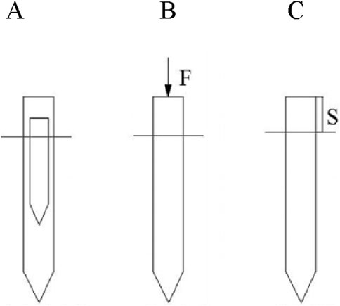
Figure 1. Finite element method of pile sinking simulation (A) Cylindrical cavity expansion (B) Force penetration method (C) Displacement penetration method.
The stress-strain path theory was proposed by Baligh (1985) in 1985. Assuming that the soil is isotropic, the penetration process of the pile bottom is replaced by a uniform flow field and a moving point source. The trajectory of the point source is regarded as a uniform cylinder. The analytical value of the displacement is obtained by using the integral of the flow field, and the distribution law of the shear stress of the pile-soil is further obtained. Sagaseta (1987) modified the theory and proposed the strain path method (SSPM). By changing the boundary conditions and considering the large deformation, the distribution of the displacement field is obtained. Luo (2004) explored the deformation law of pile-soil under the condition of pile group by considering the small deformation penetration of pile group on the basis of SSPM. Experimental study: Housel and Burkey (1948) proposed that the water pressure in cohesive soil decreases first and then increases with the pile sinking. Wang et al. (2015) monitored the displacement of the soil around the pile by static pressure pile sinking, and compared it with the displacement of the incompressible soil derived from the strain path method. The results are more consistent, and through further research, it is found that the theory is also applicable to compressible soil. Through experiments under different geological conditions, Hagerty and Peck Ralph (1971) concluded that the structural strength of soil has a great influence on the displacement of soil around piles. The greater the structural strength of soil is, the greater the displacement of soil is. Adams and Hanna (1971) comprehensively considered the squeezing effect and soil plug effect caused by pile sinking, and studied the volume relationship between the amount of pile-soil extrusion caused by pile sinking and the amount of soil at the bottom of the pile entering the inner wall of the pile. It was found that the ratio of clay to soft soil geology was about 4:3 and 2:1, respectively. Massarsch (1976) found that the pile penetration makes the soil at the bottom of the pile show spherical expansion, and the soil around the pile shows approximate cylindrical expansion, which verifies the applicability of the cavity expansion theory. Orrje and Broms (1968) measured the soil around the pile before and after the pile sinking, and concluded that with the progress of the pile sinking process, the soil was continuously squeezed out by the pile, and the original structure of the soil was destroyed, making the strength continuously reduced. Mabsout et al. (1995) simplified the pile-sinking process and obtained the distribution law of pile shaft friction resistance under different pile lengths and pile diameters. Lei et al. (2005) monitored the water pressure of pipe pile construction in soft soil area along a reconstruction and expansion highway, and put forward corresponding technical measures to reduce the rise of water pressure. Zhu and Yin (1996) studied the surface soil uplift caused by the pile sinking process, and analyzed that the pile sinking sequence had a great influence on the surface uplift. The penetration of the first pile had little effect on the surface uplift. The surface soil uplift caused by the subsequent pile was large, and with the increase of the number, the surface uplift showed an increasing trend. The penetration of the subsequent pile would cause the front pile to tilt. Fan (1998) carried out pile-sinking tests on piles of different sizes under the same geological conditions. It was found that the displacement and stress distribution of piles of different sizes after penetration were in line with the theory of circular cavity expansion. Chen et al. (1999) obtained from the static pressure single pile test in clay geology that pile sinking will cause the sinking of the soil around the pile and the uplift of the surface soil at the top of the pile, and the sum of the volume of the two is about 0.3 times the total volume of the deformed soil. Xu et al. (2000) conducted pile sinking tests under the geological conditions of saturated cohesive soil. The study found that the vertical displacement of the soil decreases rapidly from top to bottom along the pile body, and the vertical displacement is mainly concentrated in the upper 1/3 of the pile body. The horizontal displacement of the soil decreases sharply along the horizontal direction with the increase of the radial distance, and there is an obvious inflection point at 4∼5 times the pile diameter, which is also the main area of the surface soil uplift. Tang et al. (2002) carried out on-site monitoring of the changes in water pressure caused by the pile-sinking process and found that the two are in good agreement. The water pressure decreases with the increase of the radial distance and the water pressure is about 20 times the pile diameter in the radial direction (Wang et al., 2020). Circular hole expansion theory: In 1945, it was first proposed by Bishop in the “indentation hardness test theory”. Subsequently, the theory was introduced into the geotechnical field to solve related mechanical problems and has been greatly developed (Tang, 2020). Vesic (1972) derived the basic equation of the theory, assuming that the soil is an ideal elastic-plastic body, and obtained the relevant basic solution. Carter et al. (1979) used the Cambridge model to simulate the change of water pressure through the radial flow of water, and solved the corresponding results. Sagaseta et al. (1987) regarded the pile sinking process as the process of sphere penetration, and successfully obtained the vertical uplift displacement value of the soil near the pile top. Housel and Burkey (1948) regarded the pile sinking process as a quasi-static problem, and solved the displacement value of the soil around the pile. The results show that the subsequent pile penetration will cause the adjacent pile to float up. Ko et al. (2016) applied this theory to unsaturated soils, and proved that the effective stress principle and the plastic theory are still valid and applicable in different states of the same constitutive model. Gong et al. (1994) studied the displacement and stress solutions of materials with different tensile and compressive moduli, and analyzed the influence of different tensile and compressive moduli on material properties. Zheng et al. (2006) studied the squeezing effect and soil plug effect in the process of pile sinking. Considering the interaction between the two effects, the analytical solution of soil displacement was obtained on the basis of considering the soil plug effect. Based on the Cambridge model, Li et al. (2018) modified it and obtained the analytical solution of the rise and dissipation of water pressure in the process of pile sinking in saturated soil. Zhao et al. (2021) studied that sandstone is a brittle material, and the microcracks are difficult to extend when the confining stress is high. Microcracks in the samples are developed when the deviatoric stress is sufficiently high. Zhao et al. (2020) The permeability reduction can be attributed to the fracture surfaces deformation and pore space squeeze due to fracture surfaces contact crush and friction slipping. Mutual embedding of fracture surfaces and pulverized particles filling are very difficult to compensate for in the process of unloading, resulting in a significant reduction in permeability.
At present, the theoretical research of pipe pile lags behind the development of engineering practice, especially in the analysis of various influencing factors and parameter optimization. The research is not comprehensive and systematic, and it is difficult to guide the actual construction of the site. Therefore, based on the reconstruction and expansion project of Jingtai Expressway, this paper deeply studies the “pile-soil” interaction mechanism in the process of pile sinking through indoor test and numerical simulation, analyzes the evolution mechanism of “soil squeezing effect” in the process of pile sinking, and puts forward feasible construction technology to reduce the soil squeezing effect, so as to further save the project cost and improve the safety performance of the structure. The research results have direct technical support for the construction of pipe piles in the reconstruction and expansion project of Jingtai Expressway, and have reference significance for the stability evaluation and research of other pile-sinking projects.
2 Model test study on soil squeezing effect of pipe pile
2.1 Deformation measurement technology and test equipment
2.1.1 Deformation measurement technology
In recent years, with the rapid development of computer technology, digital deformation measurement technology for geotechnical test has been developed (Sagaseta, 1987). According to whether the physical markers are arranged on the experimental model, the deformation measurement methods can be divided into the punctuation method and the non-punctuation method. In this experiment, the non-punctuated digital deformation measurement method was used, and four sign pastes were pasted on the outer wall of the model box as control points. Before the image processing and analysis of the test, the control point file of the initial image must be manually established, and other work can be automatically completed by the image analysis program Geodog and its post-processing program PostViewer, so as to obtain the digital image of the displacement distribution and evolution process of the pile body and the soil around the pile during the test.
2.1.2 Testing equipment
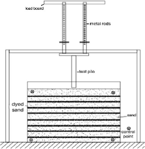
The self-designed model device was used in the experiment. The model box was made of organic glass with the bottom plate and the surrounding cementation and the top opening. The length, width and height of the model box were 100, 60 and 80 cm respectively. The model piles are organic glass half-form piles with a length of 30 cm and an outer diameter of 2–4 cm. The self-made loading frame used in the test device is made of angle steel and steel plate welded. The measurement of soil displacement is taken by a digital camera with a camera parameter of 8 million pixels and 8 times optical zoom. The test setup is shown in Figure 2.

Figure 2. Test setup diagram (A) Camera (B) Stabilization plate (C) Test pile(D) Load board (E) Force transfer rods.
2.2 Uniaxial eenetration test
2.2.1 Test scheme
The test soil sample adopts Fujian Pingtan standard sand, and its particle specific gravity G is 2.6439/cm3. The maximum and minimum dry densities are 1.749/cm3 and 1.439/cm3, respectively. The maximum and minimum void ratios are 0.848 and 0.519, respectively. The characteristic parameters of particle size composition are: Cu =1.542, Cc =1.104. During the test, each layer was paved in layers with a thickness of 4.5 cm, and 0.5 cm was paved with dyed sand for multiple tamping. The mass was weighed before each paving to ensure the uniformity of the test samples until the design height was reached.
The test pile is 30 cm long, 3 cm in outer diameter and 0.5 cm in wall thickness. The test pile is pressed in four stages. The test pile is close to the inner wall of the model box. The loading device is in place and the test pile is fixed. A digital camera is set up to capture the initial state of the soil. The static pressure grading loading was carried out by the weight accumulation method, and the mass of each weight was calibrated before the test. Install metal rods on each hole to control the elevation, first perform the first-stage loading, wait for the pipe pile to stand still for more than 1 min under the action of heavy objects, then gently lift the dowel bar, take out the first pair of metal rods, reset the dowel bar, continue to load until the pile penetrates 7.5 cm, and photograph the soil state at this time. According to this test method, the loading is continued until the pile penetrates the second 7.5 cm. The displacement state of the soil is photographed at this time, and the loading is continued until the pile is completely penetrated. The test device and pile penetration shown in Figures 3, 4.

Figure 4. Penetration test diagram of single pile (A) Initial state of soil sample (B) Penetration into 1/4 pile length (C) Penetration into 2/4 pile length (D) Penetration into 3/4 pile length.
2.2.2 Test result analysis
2.2.2.1 Soil displacement analysis
In Figure 5, it is found that at the beginning of pile sinking, the soil at the bottom of the pile is destroyed first, and the test sand moves to the bottom and both sides of the pile in a plastic flow state. The soil at the bottom of the pile mainly moves downward, and the soil at the side of the pile mainly moves on both sides. The surface soil is uplifted due to extrusion. With the increase of penetration depth, the pile body overcomes the friction of the surrounding soil to further penetrate, the movement trend of the soil changes, the compression and subsidence trend of the soil at the bottom of the pile further develops, while the trend of the soil on the pile side being squeezed does not change much, and the surface soil uplift trend gradually decreases. The particles around the pile are radial along the pile body. The shallow soil is mainly inclined upward, the middle soil is mainly horizontal, the deep particles are mainly inclined downward, and the bottom soil moves downward.

Figure 5. Soil displacement cloud map (unit: mm) (A) Penetration into 1/4 pile length (B) Penetration into 2/4 pile length (C) Penetration into 3/4 pile length (D) Penetration into 4/4 pile length.
In order to study the variation law and deformation range of soil displacement around the pile, the corresponding monitoring belts are set up at 1,3,5,7 and 9 times the pile diameter from the pile body and at the depths of 0, 8, 16, 24, 32, 40, 48 and 56 cm from the soil surface. The displacement data after the pile body is completely penetrated is extracted, and the displacement curves of the soil at different pile diameters and depths are drawn as shown in Figure 6.
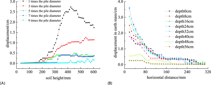
Figure 6. Diagram of soil displacement (A) Soil displacement at different pile diameters (B) Soil displacement at different depths.
It can be seen from Figure 6A that as the distance increases, the soil deformation increases first and then decreases in depth. The maximum displacement appears at 1.5 times the pile length from the surface, and the soil displacement tends to be stable at 9 times the pile diameter. It can be considered that this range is the main influence area of radial compression. From Figure 6B, it can be seen that the displacement of soil decreases rapidly with the increase of distance and tends to 0. It is obtained by fitting that the horizontal direction is basically exponential.
2.2.2.2 Soil strain analysis
The analysis of Figure 7 shows that in the early stage of penetration, the shear failure zone first appears at the end of the pile, and its width is about twice the diameter of the pile. The deformation of the soil in the shear failure zone is more complicated, which is manifested as disorderly and disorderly movement. The maximum value of shear strain does not increase with the increase of penetration depth. With the increase of penetration depth, the depth of shear failure zone increases, but the width is basically unchanged.

Figure 7. Soil shear strain cloud map (unit: mm) (A) Penetration into 1/4 pile length (B) Penetration into 2/4 pile length (C) Penetration into 3/4 pile length (D) Penetration into 4/4 pile length.
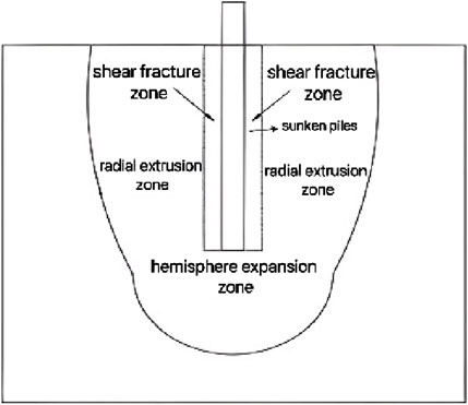
According to the characteristics of soil movement, it can be divided into three parts. As shown in Figure 8: the shear failure zone within the range of 1 times the pile diameter from the pile center; the extrusion deformation zone within 9 times the pile diameter from the pile center; the hemispherical expansion zone from the pile bottom to 1.5 times the pile length.
2.2.3 Analysis of influencing factors
2.2.3.1 Influence of pile diameter on soil displacement
In order to study the influence of pile diameter on soil displacement, the pile with diameter of 1, 2, 3, 4 cm and wall thickness of 5 mm was selected for test. From Figures 9, 10, it can be seen that with the increase of the outer diameter of the pile, the affected range of the soil increases in both width and depth, and the increase of the pile diameter makes the pile sinking pressure increase greatly, and there is a high compression zone near the bottom of the pile, that is, the orange-red area in the cloud map. The increase of the outer diameter also makes the side friction resistance and end resistance increase, and the soil pressure at the pile bottom and the pile side increases, that is, the vector arrows around the pile body in the vector diagram increase and become dense.

Figure 9. Displacement cloud diagram under different pile diameters (unit: mm) (A) Diameter 1 cm (B) Diameter 2 cm (C) Diameter 3 cm (D) Diameter 4 cm.

Figure 10. Diagram of the particle motion vector under different pile paths (unit: mm) (A) Diameter 1 cm (B) Diameter 2 cm (C) Diameter 3 cm (D) Diameter 4 cm.
2.2.3.2 Effect of wall thickness on soil displacement
Three pipe piles with different wall thickness were selected to study the influence of wall thickness on soil displacement. The outer diameter of the three model piles was 3 cm, and the wall thickness was 3, 5 and 10 mm respectively. After the pile penetration of the three working conditions is completed, the displacement cloud diagram is drawn as shown in Figure 11.

Figure 11. The displacement nephogram under different wall thickness (unit: mm) (A) Wall thickness 3 mm (B) Wall thickness 5 mm (C) Wall thickness 10 mm.
It is found in Figure 11 that the influence of wall thickness on soil displacement is similar to that of increasing outer diameter. With the increase of wall thickness, the depth and width of soil are further increased. The increase of wall thickness makes the radial movement trend of soil at the bottom of pile increase, which is manifested as extrusion deformation. The degree of extrusion deformation decreases greatly with the increase of distance (Qi et al., 2020; Ma Xiaodong, 2020; Jiang, 2017; He, 2021).
2.3 Double pile penetration test
2.3.1 Test scheme
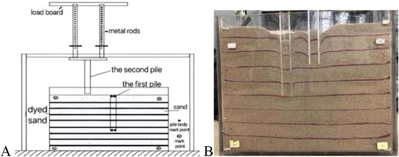
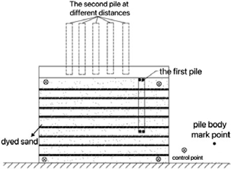
In order to study the influence of squeezing effect on adjacent piles, the double pile test is carried out on the basis of single pile test. The penetration process is consistent with the single pile test. The movement process of the first pile is identified by the camera through the marker points on the pile wall, so as to measure its displacement and determine its deflection form. Considering the friction and restraint of the model box wall and the soil on the pile, when the pile spacing is large, the displacement of the first pile is not obvious and it is difficult to be identified by the camera. Therefore, the distance between the two piles is 2 times the pile diameter, as shown in Figure 12.
2.3.2 Test result analysis
2.3.2.1 Soil displacement analysis
From Figure 13, it can be seen that the spherical hole expansion trend of the soil as a whole is obvious. In the initial stage of the second pile penetration, the existence of the pile end resistance makes the soil at the pile end compressed on the one hand, and on the other hand, it makes the soil at the pile end. The area of expansion becomes larger, but due to the hindrance of the first pile, the trend of the soil moving to the left is blocked, and then it moves to the right side, and the displacement field is no longer symmetrically distributed. When the second pile continues to penetrate, the soil displacement field on the left side of the first pile still has no significant change, and the change of the right side displacement field is significantly larger than that of the left side. The soil at the bottom of the pile is squeezed by the pile penetration. The trend of downward movement is further increased, and the deformation range in the depth area is increased.
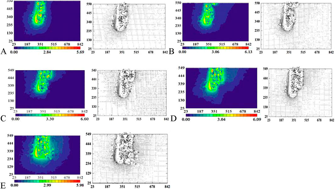
Figure 13. Displacement field of double pile penetration test (unit: mm) (A) After the first pile penetration is completed, the displacement nephogram and vector diagram (B) The displacement nephogram and vector diagram when the second pile is penetrated into 1/4 of the pile(C) The displacement nephogram and vector diagram when the second pile is penetrated into 2/4 of the pile (D) The displacement nephogram and vector diagram when the second pile is penetrated into 3/4 of the pile (E) The displacement nephogram and vector diagram when the second pile is penetrated into 4/4 of the pile.
2.3.2.2 Pile displacement and deflection form
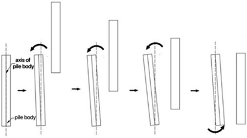
In the double pile test, the horizontal changes of the mark points of the pile top and the pile bottom collected by the camera with the pile sinking process are recorded to Table 1. The mark points of the pile body are measured in pixel coordinates. The increase indicates the rightward movement, and the decrease indicates the leftward movement. It can be seen from Table 1 that in the early and middle stages of the second pile penetration, the top of the first pile moves to the left, while the bottom does not move, which can be regarded as the counterclockwise rotation of the pile around the bottom. In the later stage of the second pile penetration, the top of the left pile does not move, while the bottom moves to the left, which can be regarded as the clockwise rotation of the pile around the top. The deflection of the first pile caused by the penetration of the second pile is mainly caused by rotation, and the deformation of the second pile is caused by translation. The whole deflection process is shown in Figure 14.
2.3.3 The influence of pile spacing on soil compaction effect
In order to study the influence of different pile spacing on the squeezing effect, different pile spacing is selected to carry out the double pile test, only the distance between the two piles is changed, and the other conditions are consistent with the previous double pile test. The specific working conditions are shown in Table 2, and the test diagram is shown in Figure 15.
After the penetration of the pile, the Geodog analysis software is used to extract the displacement and shear strain. The displacement field and shear strain field of different working conditions are shown in Figures 16, 17, respectively. It can be seen from the figure that when the pile spacing is 3 times the pile diameter, the soil between the piles is hindered by the piles on both sides, and the horizontal movement trend is limited. It can only sink with the penetration of the piles on both sides, and is subject to shear failure. The pile spacing is small, so that the width of the soil between the piles is narrow, and the friction constraint on the pile side is small. It cannot resist the extrusion failure during the penetration of the pile, and the overall strength of the soil between the piles is destroyed. With the further penetration of the pile, the soil between the piles sinks sharply. At this time, the pile spacing obviously cannot meet the bearing requirements, and the soil between piles cannot bear the load. With the increase of pile spacing, the soil between piles begins to appear in the area where it is not sheared and does not move sharply downward. At this time, the soil between piles can play a bearing role, and the side friction resistance of piles can also restrain the movement of piles.

Figure 16. Displacement field under different spacing (unit: mm) (A) 3 times spacing (B) 4 times spacing (C) 5 times spacing (D) 6 times spacing.

Figure 17. Shear strain field at different spacings (unit: mm) (A) 3 times spacing (B) 4 times spacing (C) 5 times spacing (D) 6 times spacing.
In summary, considering the displacement and shear strain of the soil between piles, the pile spacing should be set to more than 4 times the pile diameter in order to better play the synergistic bearing role of the pile group.
2.4 The influence of pile-sinking sequence on soil squeezing effect
In practical engineering, the bearing capacity of soft soil foundation reinforced by pipe pile is exerted by the synergistic effect of pile group. The research shows that (Zhu, 2020): the different construction sequence of pipe pile will also have a great influence on the stress state of pile soil and the displacement of soil.
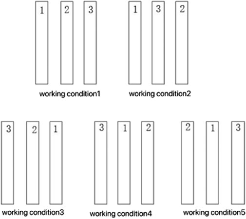
This section aims to study the influence of different construction sequences on soil displacement. According to the existing research and combined with this indoor test, five different construction sequences are designed, as shown in Figure 18. Three pile tests were used in the five working conditions, and the pile was marked as the penetration sequence of the pile. The corresponding monitoring belt was set up at 3 times the pile diameter on the left side of the most left pile to monitor the change of soil displacement before and after the penetration of each pile.
After the test is completed, the displacement fields of the five working conditions shown in Figure 18 are extracted, and the soil displacement curve at the monitoring band is drawn as shown in Figure 19. Comparing the displacement field under each construction sequence, it does not show obvious regularity, but the soil displacement changes at the monitoring zone in each working condition are quite different. In terms of each construction sequence, the pipe pile close to the monitoring zone should be penetrated first and then the pipe pile far away from the monitoring zone should be penetrated, that is, the construction should be carried out in the order from near to far.
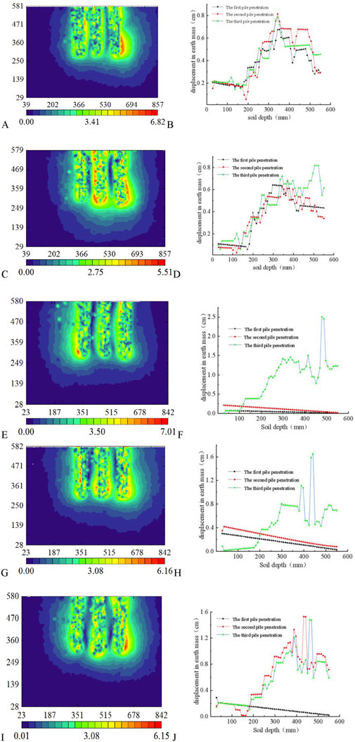
Figure 19. Displacement diagram under different construction sequence (unit: mm) (A) The displacement field of condition 1 (B) The cumulative displacement of condition 1 (C) The displacement field of condition 2 (D) The cumulative displacement of condition 2 (E) The displacement field of condition 3 (F) The cumulative displacement of condition 3 (G) The displacement field of condition 4 (H) The cumulative displacement of condition 4 (I) The displacement field of condition 5 (J) The cumulative displacement of condition 5.
By comparing the changes of soil displacement and its displacement value under different construction sequences, it can be seen that the order of ' from near to far should be selected first in actual construction, that is, the pipe piles near the subgrade or protected buildings should be hit first, so as to protect the subgrade or protected buildings and reduce the damage caused by the subsequent pile penetration in the distance.
3 Evolution mechanism of soil compaction effect of pipe pile
3.1 Establishment of the model
The change of soil around the pile is analyzed by PFC 2D simulation of single pile penetration, focusing on the change of soil displacement and meso parameters with pile penetration, and the formation process and evolution mechanism of soil squeezing effect in soft clay are studied.
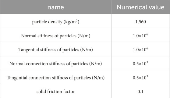
The pile is simulated by wall element, the length is 0.5 m, the outer diameter is 4 cm, the inner diameter is 2.8 cm, the wall thickness is 1.2 cm, the normal and tangential stiffness are 1.5 × 10⁸ N/m and 1.0 × 10⁸ N/m respectively, the friction coefficient is 0.5, and the model pile is shown in Figure 20A. The length and width of the model box are 2 and 1 m respectively, and the ratio of model box width to pile diameter is 25, which can effectively avoid the influence of boundary effect on pile-soil displacement. The radius of soil particles is 2 ∼ 4 mm, the average radius is 3 mm, and the total number is about 18,000. In order to better intuitively show the deformation of soil particles during pile penetration, the particles are layered and dyed, each layer is 10 cm high, a total of 10 layers, the particle parameters are shown in Table 3, and the particle layered dyeing is shown in Figure 20B.

Figure 20. Numerical simulation model (A) Model piles (B) Soil particle staining diagram (C) Measurement circle layout diagram.
The data information of a single particle is discrete. The common practice is to arrange the measurement circle in the model, and take the mean value of the data information of the local particles as the micro-response of the soil. This time, a total of 800 measurement circles are set up, 20 × 40 distribution, diameter is 0.05 m, full of models, and the arrangement of the measurement circle is shown in Figure 20C. In this simulation, the velocity loading method is used to apply a certain vertical velocity to the pile, and the velocity is set to −0.1 m/time step.
3.2 Analysis of effect
In order to study the deformation of the soil with the penetration of the pile, the particle state is recorded once every 12.5 cm of the pile, that is, 1/4 pile length. The particle motion in the four stages is shown in Figure 21, and the force chain change is shown in Figure 22.

Figure 21. Particle motion (A) Penetration of 1/4 pile length (B) Penetration of 2/4 pile length (C) Penetration of 3/4 pile length (D) Penetration of 4/4 pile length.
3.2.1 Particle motion
It can be seen from Figure 21 that when the pile sinking depth is 1/4 pile length, the shallow soil deformation is large, and the surface uplifts. The soil particles on the pile side gradually move down with the pile body, and the soil layer under the pile is compressed and deformed. The height difference between the soil inside and outside the pipe pile appears. With the sinking of the pile body, the downward movement trend of the particles around the pile is further intensified. The uplift value at the surface is increasing, and the horizontal range of the uplift is increasing. The height difference between the internal and external soil is increasing.
By analyzing the soil state after the pile penetration is completed, it can be found that the height of the pile top is significantly lower than the height of the surface soil. Through the monitoring of particle displacement, it can be found that the maximum uplift of the surface soil is about 3 cm, the maximum uplift position is 2 times the pile diameter from the pile center, and the horizontal range of the surface uplift is about 10 times the pile diameter.
3.2.2 Particle contact
The PFC force chain thickness represents the magnitude and density of the contact force between the particles. In the PFC numerical simulation, the contact force between particles is visualized by the force chain, and the thicker the force chain, the greater the contact force between the particles, and the denser the contact in this area. Changes in the thickness of the force chain can reflect changes in the contact between the particles and the range of contact. When the contact force between particles increases, the force chain becomes thicker, indicating that the contact degree increases. At the same time, the expansion and distribution of the force chain can also show changes in the contact range. It can be seen from Figure 22 that as the penetration depth increases, the contact degree and range of the force chain decrease, indicating that the penetration of the pile is a process in which the contact of the soil around the pile is gradually destroyed. A small amount of soil particles at the bottom of the pile enter the pile to form a soil plug, and the soil here is highly compressed.
3.2.3 Soil displacement
It can be seen from Supplementary Figure S1 that when the pile is just penetrated into the soil, the soil around the pile moves violently, which is manifested as the soil is squeezed out by the pile. With the further penetration of the pile, the trend of the soil around the pile is gradually weakened. The pile body overcomes the soil friction and continues to penetrate. The soil at the bottom of the pile is mainly squeezed and deformed, and the soil around the pile is mainly radially compressed. When the soft clay is destroyed by extrusion, it will form a local failure block due to its own cohesion, which is not uniformly attenuated like the sand used in the indoor test. The closed displacement contour circle of 0.06 cm appears on the pile side in the figure, and the affected range in the depth direction of the soil is about 1.2 times the pile length, which is less than the influence range of 1.5 times the pile length in the sand.
It can be seen from Supplementary Figure S2 that when the pile sinking begins, the particles at the end of the pile move downward, the particles on the side of the pile are squeezed and move upward, and the movement trend of the soil around the pile is not obvious. With the progress of pile sinking, the movement trend of particles at the bottom and side of the pile is further developed, and the influence range is further increased. The particles at the surface move upwards, which is macroscopically manifested as the uplift of the surface. There are obvious directional differences in the movement of particles on the side of the pile. The upper particles on the left are mainly inclined upward, while the lower particles on the right are mainly horizontal, that is, there is an obvious displacement slip zone, as shown in the figure. By synthesizing the displacement values of each particle in x and y directions, the movement angle of each particle can be obtained, as shown in the figure. As the pile continues to penetrate, the displacement sliding zone moves down, and the movement angle of the particles on the surface continues to decrease.
3.2.4 The change of microscopic parameters
It can be seen from Supplementary Figure S3 that in the initial stage of pile penetration, the soil under the pile is compressed. With the continuous penetration of the pile, the trend of soil movement continues to develop downward, and the deformation of the soil turns to develop on both sides. After the pile is pressed, a spherical high porosity area appears at the bottom of the pile, and its overall law is attenuated from the pile to the surrounding. In the process of pile sinking, the sinking of the pile will squeeze the soil on the side of the pile and the bottom of the pile, resulting in lateral displacement and vertical uplift of the soil around the pile. This effect is especially evident at the bottom of the pile, when the pile continues to sink and penetrate the soil layer, the soil at the bottom of the pile is subjected to greater extrusion and shearing, resulting in the destruction of the soil structure and the rearrangement of the particles, forming a high porosity zone. The greater the penetration depth, the stronger the extrusion and shear effect of the soil at the bottom of the pile, and the greater the increase in porosity. However, this increase is not linear, because the soil properties, construction parameters and other factors will also have an impact on the porosity distribution, when the penetration depth reaches a certain value, the extrusion and disturbance of the soil at the bottom of the pile tend to be stable, and the range and degree of the high porosity zone no longer increase significantly.
4 Conclusion
(1) Through the visual test device combined with digital deformation measurement technology, the influencing factors of soil squeezing effect in the pile sinking process mainly include: pile diameter, wall thickness, pile spacing, pile sinking sequence, soil compactness and pile sinking speed.
(2) According to the movement characteristics of the soil, it can be divided into three parts: the shear failure zone within the range of 1 time the pile diameter from the pile center; the extrusion deformation zone within 9 times the pile diameter from the pile center; the hemispherical expansion zone from the pile bottom to 1.5 times the pile length. The change of soil deformation caused by pile sinking in depth shows the characteristics of increasing first and then decreasing. The maximum displacement is at 1.5 times the pile length. The change of soil deformation in the horizontal direction shows an exponential decrease, and the effective influence range is about 9 times the pile diameter. The width of the shear strain zone does not change with the increase of penetration, which is about 2 times the pile diameter.
(3) The increase of radius and wall thickness makes the squeezing effect more obvious, and the horizontal influence width and vertical influence depth increase. Due to the increase of pile resistance, the pile side wall and the soil at the bottom of the pile have a high squeezing area.
(4) For double piles, the expansion trend of the inner side of the two piles is smaller than that of the outer side of the pile. The squeezing effect will cause the adjacent pile to produce translation and rotation, and the rotation is the main. When the subsequent pile penetration is completed, the displacement field no longer presents a basically symmetrical state, and the influence range in the depth area increases. When the pile spacing is 3 times the pile diameter, the soil between the piles is hindered by the piles on both sides, and can only sink with the penetration of the piles. It is subjected to shear failure and cannot resist the extrusion during the penetration of the piles. The friction constraint on the pile side is small and cannot meet the bearing requirements. The pile spacing should be set to more than 4 times the pile diameter in order to better play the synergistic bearing role of pile groups.
(5) In the actual construction, the construction sequence from near to far should be preferentially selected, that is, the pipe piles close to the roadbed or the protected buildings should be drilled first to isolate the propagation path of soil deformation caused by subsequent pile penetration. The shielding effect of the first penetration pile can reduce the damage of the subsequent penetration pile to the roadbed or the building.
(6) The distribution law of soil displacement field during pile penetration is similar to the test results in sand, but the influence depth is small. In the process of pile sinking, there is an obvious displacement sliding zone in the soil on the pile side. The movement of the upper particles is mainly above the slope, and the movement of the lower particles is mainly horizontal. With the increase of pile penetration, the displacement sliding zone gradually moves down.
Data availability statement
The original contributions presented in the study are included in the article/supplementary material, further inquiries can be directed to the corresponding author.
Author contributions
SZ: Writing–review and editing. XZ: Writing–original draft.
Funding
The author(s) declare that no financial support was received for the research, authorship, and/or publication of this article.
Acknowledgments
We deeply appreciate the warm and efficient work of the editors and reviewers.
Conflict of interest
The authors declare that the research was conducted in the absence of any commercial or financial relationships that could be construed as a potential conflict of interest.
Publisher’s note
All claims expressed in this article are solely those of the authors and do not necessarily represent those of their affiliated organizations, or those of the publisher, the editors and the reviewers. Any product that may be evaluated in this article, or claim that may be made by its manufacturer, is not guaranteed or endorsed by the publisher.
References
Adams, J. I., and Hanna, T. H. (1971). Ground movement due to pile driving. London: Instruction of civil engineers, 127–133.
Baligh, M. M. (1985). Strain path method. J. geotechnical Eng. 11 (9), 1108–1136. doi:10.1061/(asce)0733-9410(1985)111:9(1108)
Carter, J. P., Randolph, M. F., and Wroth, C. P. (1979). Stress and pore pressure changes in clay during and after the expansion of a cylindrical cavity. Int. J. Numer. Anal. Methods Geomechanics 3 (4), 305–322. doi:10.1002/nag.1610030402
Chen, W., Shi, J. Y., and Gong, Y. P. (1999). Centrifugal model test on squeezing effect of jacked pile in saturated clay. J. Hohai Univ. Nat. Sci. Ed. (06), 103–109.
Fan, L. B. (1998). The mechanism and countermeasures of pile driving and elevation. J. Zhejiang Univ. Technol. (01), 73–77.
Gong, X. N., Wang, Q. T., and Luo, X. (1994). The problem of cavity expansion of materials with different tensile and compressive modulus. J. Appl. Mech. (04), 127–132.
Hagerty, D. J., and Peck Ralph, B. (1971). Heave and lateral movements due to pile driving. J. Soil Mech. Found. Div. 11, 1513–1532. doi:10.1061/jsfeaq.0001700
He, H. (2021). Numerical simulation analysis of soil squeezing and soil plug effect in pipe pile construction of soft soil foundation in Shenzhen. Water Conservancy Plan. Des. (06), 141–147.
Housel, W. S., and Burkey, J. R. (1948). Investigation to determine the driving characteristics of piles in softclay. Proceeding 2nd Int. Conf. Soil Mech. Found. Eng. 5, 146–154.
Ko, J., Jeong, S., and Joon, K. L. (2016). Large deformation FE analysis of driven steel pipe piles with soil plugging. Comput. Geotechnics 6 (17), 82–97. doi:10.1016/j.compgeo.2015.08.005
Lei, J. B., Xu, Z. Z., Jiang, H. D., and Xu, Y. M. (2005). Analysis and research on the variation law of excess pore water pressure in the process of precast pile sinking. Highw. Traffic Technol. (11), 29–33.
Li, J. P., Cui, J. F., Li, L., and Zhao, G. W. (2018). The influence of static pressure pile sinking on the deformation of adjacent underground continuous wall. J. Shanghai Jiao Tong Univ. (12), 1580–1586. doi:10.16183/j.cnki.jsjtu.2018.12.006
Li, W. J.(2021). Analysis of the impact of pile foundation construction on surrounding buildings journal of zhengzhou railway vocational and technical college. (02):14–17. doi:10.13920/j.cnki.zztlzyjsxyxb.2021.02.005
Luo, Z. Y. (2004). Study on soil squeezing effect and construction measures of jacked pile. Hangzhou: Zhejiang University.
Mabsout, M. E., Reese, L. C., and Tassoulas, J. L. (1995). Study of pile driving by finite-element method. J. Geotechnical Eng. 121 (7), 535–543. doi:10.1061/(asce)0733-9410(1995)121:7(535)
Ma Xiaodong (2020). Study on the influence of pile group arrangement and nonuniform sand on local scour Master's thesis. Beijing Jiaotong University. doi:10.26944/d.cnki.gbfju.2020.003228
Orrje, O., and Broms, B. B. (1968). Closure to “effects of pile driving on soil properties”. J. Soil Mech. Found. Div. 94 (6), 1379–1380. doi:10.1061/jsfeaq.0001208
Qi, C. G., Zheng, J. H., Lai, W. J., Wang, X. Q., and Shan, Y. L. (2020). Source-sink theory analysis of soil compaction effect of open-ended pipe pile and comparative study of transparent soil test. J. Appl. Found. Eng. Sci. (04), 938–952. doi:10.16058/j.issn.1005-0930.2020.04.016
Sagaseta, C. (1987). Analysis of undrained soil deformation due to ground loss. Géotechnique 37 (3), 301–320. doi:10.1680/geot.1987.37.3.301
Sagaseta, C., Houlsby, G. T., and Norbury, J. (1987). Quasi-static undrained expansion of a cylindrical cavity in clayin the presence of shaft friction and anisotropic initical stresses. University of Oxford.
Tang, M. (2020). Application of prevention and control measures for soil squeezing effect of static pressure pile. Shanghai Constr. Technol. (04), 65–67.
Tang, S. D., He, L. S., and Ye, Z. H. (2002). Lateral earth pressure increment caused by pile foundation construction in soft soil foundation. J. Geotechnical Eng. (06), 752–755.
Vesic, A. S. (1972). Expansion of cavities in infinite soil mass. J. Soil Mech.98 (3), 265–290. doi:10.1061/jsfeaq.0001740
Wan, X., Ding, J. W., Huang, C., and Ding, C. (2020). Field test study on the squeezing effect of pile group in layered foundation soil. J. Southeast Univ. ( Nat. Sci. Ed. ) 50 (06), 1090–1096.
Wang, B., Wang, Z. T., Wang, B. D., Zhang, J., and Huang, K. (2020). Numerical simulation of the influence of soil compaction effect on the timeliness of pipe pile bearing capacity. Ind. Archit. Acad. Exch. Pap. II, 1321–1324+1320. doi:10.26914/c.cnkihy.2020.024444
Wang, M., Chu, Zh.J., Shi, Sh.Q., and Sun, J. H. (2015). Soil squeezing displacement of single pile of pressed pipe pile based on strain path method. J. Coll. Logist. Eng. (04), 23–30.
Xu, J. P., Zhou, J., Xu, C. Y., and Zhang, C. Y. (2000). Model test study on soil compaction effect of pile sinking. Geomech. (03), 235–238. doi:10.16285/j.rsm.2000.03.011
Zhang, J. L. (2021). Soil squeezing effect analysis of pile foundation construction in deep silt site. Baoding: Hebei University. doi:10.27103/d.cnki.ghebu.2021.001725
Zhao, Y., Bi, J., Wang, C. H. L., and Liu, P. (2021). Effect of unloading rate on the mechanical behavior and fracture characteristics of sandstones under complex triaxial stress conditions. Rock Mech. Rock Eng. 54 (54), 4851–4866. doi:10.1007/s00603-021-02515-x
Zhao, Y., Wang, Z. H. L., and Bi, J. (2020). Analysis of fractured rock permeability evolution under unloading conditions by the model of elastoplastic contact between rough surfaces. Rock Mech. Rock Eng. 53, 5795–5808. doi:10.1007/s00603-020-02224-x
Zheng, J. J., Nie, C. J., and Lu, Y. E. (2006). Analytic solution of cylindrical cavity expansion problem based on soil plug effect. J. Rock Mech. Eng. (S2), 4004–4008.
Zhou, M., Han, Y. W., Zhou, X. W., and Xiao, Z. W. (2021). Squeezing effect of large-diameter pile driving in marine soft clay. J. Guangdong Ocean Univ. 41 (01), 90–96.
Zhou, X. W., Li, J. Q., Zhou, M., and Xiao, Z. W. (2022). Study on the soil squeezing effect of pipe pile steel die with spudcan. J. Harbin Inst. Technol. (02), 1–13.
Zhu, H., and Yin, Z. Z. (1996). Finite element analysis of pile driving effect. J. Hohai Univ. (01), 56–61.
Keywords: evolution mechanism, influencing factors, load bearing characteristics, pile-soil deformation, soil squeezing effect
Citation: Zhang S and Zhang X (2025) Study on influencing factors of soil compaction effect of pipe pile in soft soil area. Front. Earth Sci. 12:1495866. doi: 10.3389/feart.2024.1495866
Received: 13 September 2024; Accepted: 20 November 2024;
Published: 06 January 2025.
Edited by:
Chong Xu, Ministry of Emergency Management, ChinaReviewed by:
Jing Bi, Guizhou University, ChinaZhanping Song, Xi’an University of Architecture and Technology, China
Lei Gao, Hohai University, China
Copyright © 2025 Zhang and Zhang. This is an open-access article distributed under the terms of the Creative Commons Attribution License (CC BY). The use, distribution or reproduction in other forums is permitted, provided the original author(s) and the copyright owner(s) are credited and that the original publication in this journal is cited, in accordance with accepted academic practice. No use, distribution or reproduction is permitted which does not comply with these terms.
*Correspondence: Xinyuan Zhang, MjAyMzE1NTEwMkBzdHUuc2RqenUuZWR1LmNu
 Sifeng Zhang
 Xinyuan Zhang