- 1CCTEG Coal Mining Research Institute, Beijing, China
- 2Coal Mining and Designing Department, Tiandi Science and Technology Co., Ltd., Beijing, China
- 3Xinjiang Energy Co., Ltd., CHN Energy, Erumqi, China
In order to explore a new method and mode of gently inclined hard roof treatment, the hydraulic fracturing axial roof cutting technology based on abrasive jet is introduced, and the key technical parameters of abrasive jet axial cutting and fracturing are determined based on indoor experiments and field industrial experiments. Taking the mining of working face under the condition of hard roof in Kuangou Coal Mine as the background, the implementation process and the effect of mining process are tested by means of water pressure gauge, drilling peep and observation well water level observation, mi-croseismic monitoring, support fracture monitoring and coal stress monitoring. The research results show that the key technical parameters of slotting and fracturing are mastered in the axial cutting test of abrasive jet. Wherein the kerf depth is 200 m, the kerf length is 300 m, the kerf pressure is 40–50 mpa, the fracturing pressure is 50–55 mpa, and the fracturing time is 20–30 min. After grooving fracturing, the cracks in the roof strata are effectively generated and expanded, which destroys the integrity of the roof, and the fracturing radius is 10–20 m. During the mining period, compared with the tradi-tional blasting technology, the concentrated area of microseismic events was shifted from 80 m in front of the working face to 130 m after the combined treatment of abrasive jet axial roof cutting and blasting, and the microseismic energy release was mainly small energy events. After the application of abrasive jet axial roof cutting and scour prevention technology in hard roof, the periodic weighting step is obviously reduced, the influence range of mining stress and stress concentration coefficient are obviously reduced, the activity intensity and dynamic load effect of surrounding rock are obviously weakened. The research results provide a basis for effective prevention and control of rockburst disasters under the condition of hard roof.
1 Introduction
With the increasing depth of coal mining, rockburst accidents occur frequently. Ac-cording to statistics, there are more than 170 rockburst mines in China. Hard roof is one of the main disaster-causing factors of rock burst or strong ground pressure during coal mining. Its hard roof has the characteristics of good integrity, high strength and strong ability to bear overlying load, which provides high static load and strong dynamic load for the occurrence of rock burst (Pan et al., 2003; Pan et al., 2012).
At present, the methods of blasting roof breaking and hydraulic fracturing are widely used at home and abroad to weaken the hard roof. In view of the large-area hanging roof of the working face during the initial mining under the condition of hard roof, Zhao (2021) put forward the cooperative anti-scour mechanism of deep-hole roof pre-splitting blasting. Kuangou Coal Mine has been seriously affected by hard roof for a long time. A systematic study was carried out on the reasonable control height of hard roof in close-distance coal seam in Kuangou Coal Mine, and the key technical parameters of roof blasting presplitting were optimized, which effectively reduced the activity intensity of hard roof and the stress concentration of coal body. The combined method of directional long-distance drilling and blasting roof cutting was used to effectively relieve the pressure of the hard roof (Zhang et al., 2019; Jia et al., 2022; Jia et al., 2024). As an effective method to weaken the hard roof and relieve the pressure of sur-rounding rock, hydraulic fracturing technology has been widely used in the prevention and control of rock burst of hard roof (Junzhe et al., 2020). On the basis of scaling analysis, Ali Naghi Dehghan and others scaled the laboratory experimental parameters to simulate the hy-draulic fracturing process under field conditions (Dehghan, 2020). Some scholars use numerical simula-tion and rock mechanics test methods to analyze the influence of natural fractures on hy-draulic fracturing aperture and fracture propagation geometry (Cruz et al., 2018; Liu et al., 2014). Qingyuan He et al. obtained that the homogeneity of rock mass significantly affects the propagation distance of hydraulic fracture from its starting point in its predetermined direction before reorienta-tion (He et al., 2017). Shuai Heng et al. developed a two-dimensional numerical model of hydraulic fracturing to clarify the evolution of hydraulic fractures and their non-planar behavior at the level (Heng et al., 2019). Based on the finite-discrete method, Mingyang Wu et al. mastered that when the elastic modulus of discrete embedded blocks and the number of discrete embedded cracks reach a certain level, the propagation of hydraulic cracks will suddenly change (Wu et al., 2021). Mingqi Qin and others studied the mechanism of hydraulic frac-turing of layered rock mass based on the hydraulic fracturing model of surrounding dy-namics (Qin et al., 2021). Ayaka Abe et al. studied the formation law of fracture network when hydrau-lic fractures and pre-existing fractures interact through laboratory-scale hydraulic frac-turing experiments (Abe et al., 2021). Arash Dahi Taleghani and others discussed the linear elastic fracture mechanics, cohesive element method and continuous damage mechanics tech-niques for understanding the interaction between hydraulic fractures and natural frac-tures (Taleghani et al., 2016). Amir Ghaderi and others combine the extended finite element method (XFEM) with the discrete element method (DEM) to identify the propagation of hydraulic fractures in porous media containing natural fracture blocks (Ghaderi et al., 2018). Ali Naghi Dehghan et al. con-ducted laboratory experiments on the size synthetic rock samples, and grasped the influ-ence of the pre-dip angle and strike of fractures on the propagation behavior and geometry of hydraulic fractures (Dehghan et al., 2018). Kang et al. (2023) developed a complete set of technology and equipment for hydraulic fracturing in underground areas of coal mines, focusing on the propagation law of hydraulic cracks at different scales. Junfeng et al. (2023) put for-ward the method of hydraulic fracturing “artificial liberation layer” to relieve pressure and prevent rockburst in the area of thick hard roof where the overlying coal seam caused dis-aster, and Mengshan mining area introduced hydraulic fracturing technology to explore a new mode of rockburst control (Weng et al., 2019). In addition, relevant scholars have studied the impact of land settlement caused by tunnel excavation and the coordination of cable-soil deformation under different anchoring conditions. It provides conditions for the safe conduct of the project site (Junfeng et al., 2021; Wu et al., 2020; Irani et al., 2022).
With the rapid development of high-pressure abrasive water jet technology in recent years, Junfeng et al. (2021) obtained the variation law of fracture characteristic index values such as rock failure depth, width and erosion volume under different hydraulic parameters through laboratory tests. Xia et al. (2020) developed a new technology of axial top-cutting fracturing with abrasive jet in hole and hydraulic reaming and cutting in coal seam, and further developed the hydraulic fracturing technology and technology. Domestic scholars (Feng, 2012; Li et al., 2009) established the empirical model of cutting depth and surface roughness in smooth area of abrasive water jet machining hard and brittle materials, and put forward the pressure relief mechanism of high-pressure water jet grooving coal seam. In addition, in other aspects of research on rock burst, some scholars have analyzed the precursor characteristics of rock burst, and introduced loading and unloading response ratios to study the reasonable advancement speed of their working faces (Feng et al., 2022; Lai et al., 2022).
The research results of the above scholars have made effective research on the preven-tion and control of blasting pressure relief, hydraulic fracturing and pressure relief of hard roof. However, there is relatively little research on the application of pressure relief pre-vention and control of abrasive jet. In view of this, this paper takes the mining of I010206 working face in Kuangou Coal Mine as the research object, and carries out the determina-tion of key technical parameters of axial roof cutting with abrasive jet. Using this technology, the pre-splitting engineering practice of combining abrasive jet with blasting is carried out, and the effect is tested. It is verified that the axial cutting technology of hard roof abrasive jet can achieve the effect of conventional blasting treatment in hard roof. The purpose of this paper is to lay a foundation for comprehensive application in the practice of rock burst prevention and control of hard roof in Kuangou Coal Mine.
2 Engineering background
2.1 General situation of working face
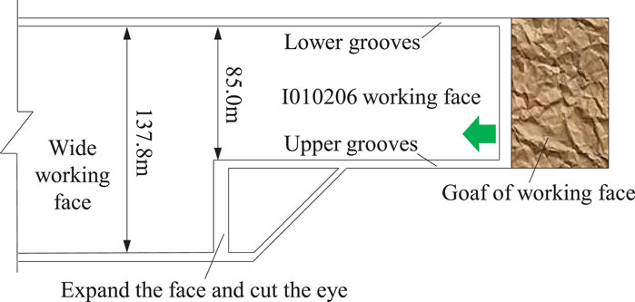
Kuangou Coal Mine is located in Hutubi County, Xinjiang, China. The mine mainly mines B4-1 coal seam, B2 coal seam and B1 coal seam. Now it is mined to I010206 working face of B2 coal seam, with an average thickness of 10.5 m, which belongs to extra-thick coal seam. Before expansion, the inclined length is 85 m, after expansion, the inclined length is 137.8 m, the recoverable strike length is 1,672 m, the average inclination angle of working face is 14, and the average buried depth is 434 m. The width of I010206 working face is ir-regular during mining, and the layout of I010206 working face is shown in Figure 1. I010206 working face of B2 coal seam adopts comprehensive mechanized top-coal caving mining technology, with a mining thickness of 3.2 m and a caving thickness of 7.3 m, with a mining-caving ratio of about 1: 2.4.
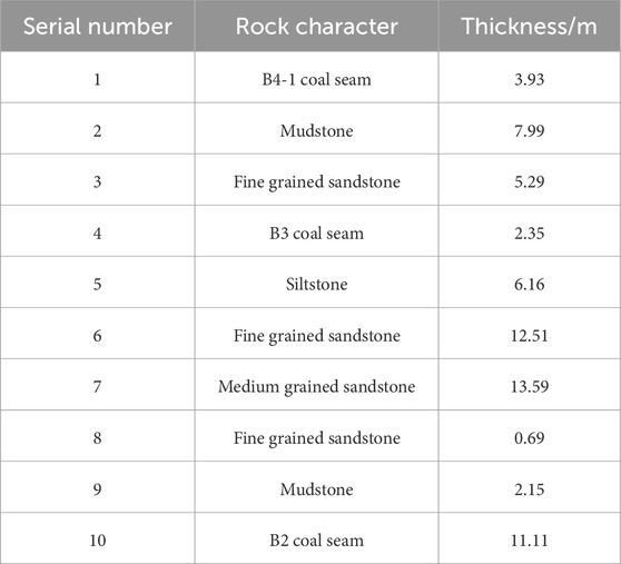
According to the analysis of borehole data in Kuangou Coal Mine, there are multiple sandstone roofs within 50 m above the coal seam. The lithology statistics of B2 coal seam and its roof are shown in Table 1. There are 13.59 m thick medium-grained sandstone and 12.51 m thick fine-grained sandstone in the roof of coal seam. Among them, 13.59 m me-dium-grained sandstone is a sub-critical stratum, with uniaxial compressive strength of 115.25 MPa, uniaxial tensile strength of 7.48 MPa, elastic modulus of 31.65 GPa and Pois-son’s ratio of 0.24.
2.2 The strata behavior of previous working face mining in B2 coal seam
After I010203 working face of B2 coal seam is mined, I010206 working face is mined. During the mining period of I010203 working face in the past, rock burst and many mine earthquakes occurred. Taking the large energy appearance of mine earthquake on 8 March 2018 as an example, the source distribution of mine earthquake and its roadway defor-mation are drawn as shown in Figure 2. During the mining of I010203 working face in B2 coal seam, a mine earthquake occurred at the side of coal pillar in the lower gateway. The energy of mine earthquake is 9.7 × 10⁶ J, and the source is at the side roof of coal pillar in the lower gateway of I010203, as shown in Figure 2A. The mine earthquake was accompanied by loud noise, which caused floor heave and net pocket at the bottom of roadway in the area of 148–198 m ahead of the working face in the lower gateway of I010203. The floor heave of the roadway where the mine earthquake occurred is about 20 cm, and the local top coal sinks about 30 cm, as shown in Figure 2B.
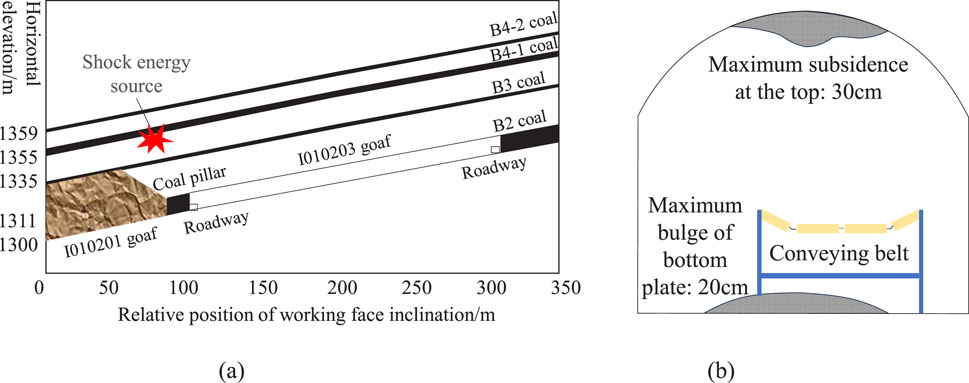
Figure 2. The source distribution of mine earthquake and its roadway deformation. (A) Focal location of mine earthquake; (B) Roadway deformation caused by mine earthquake.
2.3 I010206 working face impact risk analysis
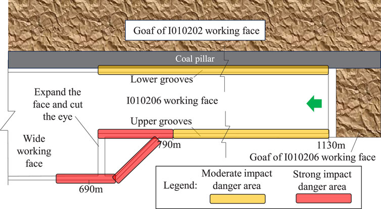
This paper comprehensively analyzes the main geological factors and mining tech-nology factors that affect the risk of rock burst in I010206 working face of Kuangou Coal Mine. The main geological factors include physical properties of coal and rock, buried depth, hard rock stratum, faults, local fold areas and so on. The main mining factors are overlying structure, section coal pillar, roof activity, liberated layer, bottom coal, roadway crossing and so on. The comprehensive index method is used to carry out the impact risk assessment, and the multi-factor coupling method is used to draw the results of impact risk area division as shown in Figure 3.
B2 coal seam and its floor have weak impact tendency, and B2 coal seam roof has strong impact tendency. As can be seen from Figure 3, when I010206 working face is advancing, the danger-ous area along the gateway on the working face changes from a medium impact dangerous area to a strong impact dangerous area near the wide working face. Among them, the range of 790–1,130 m in the upper gateway is a medium impact danger zone, and the range of 690–790 m is a strong impact danger zone. In the mining process of the working face, the lower gateway area is a medium impact danger area.
3 Principle and technology of axial top cutting with frosted jet
3.1 Principle of axial roof cutting with abrasive water jet to prevent impact
The technology of axial cutting of hard roof with abrasive jet is to drill holes in the roof, and the initial cracks with a depth of 300–500 mm are formed on the wall of the hole with abrasive jet technology. Fracturing is carried out along the cutting direction, so that a fracture network dominated by axial cracks is formed in the hard roof, and a cluster frac-ture network along the strike or inclination is formed. Under the action of mine pressure, the technology of directional cutting off the roof is realized (Wu et al., 2020).
According to the related theory of rock burst, the energy sources of rock burst are mainly static load of foundation and additional dynamic load. When the combined action of dynamic and static loads reaches the critical condition of rockburst, rockburst will occur, and the conditions for rockburst can be expressed as Equation 1:
In the formula, σj is the static load in coal and rock mass; σd is the dynamic load in-duced impact in coal and rock mass; σbmin is the critical stress when rock burst occurs.
The technology of axial roof cutting with abrasive jet can reduce the bending elastic energy caused by roof hanging and the dynamic load caused by roof fracture. At the same time, the goaf fully collapses, which plays a supporting role for the roof, thus reducing the compressive elastic energy of coal and the dynamic load caused by roof collapse.
3.2 Construction technology of axial topcutting technology with scrubbed water jet
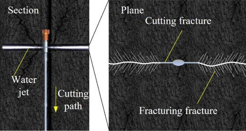
The construction technology mainly includes “drilling-slotting-fracturing” three links, and the schematic diagram of the frosted jet construction technology is shown in Figure 4. Firstly, a drilling rig, a matching drill bit and a drill pipe are used to drill a hole with a certain aperture in the roadway roof. Secondly, connect the hole sealer with the abrasive jet device and send it to the preset position of drilling, start the water jet system and adjust it to the jet mode. Operate the drilling rig to retreat the drill pipe at a uniform speed, and form prefabricated cracks on both sides of the drilling axis. Finally, turn off the abrasive pump, adjust the high-pressure pump to hole sealing mode, and inject high-pressure water into the hole sealer to seal the upper and lower hole sealers of the crack. Switch the water jet system to fracturing mode, and the high-pressure water continues to expand along the crack tip.
When the pump pressure drops suddenly or the fracturing time reaches the design time, turn off the high-pressure pump, relieve the pressure with the hole sealer, and com-plete the fracturing work in this section. Start the drilling rig and operate the drill pipe to move the ejector to the next slot position, and construct the next section according to the above method.
4 Experimental study on main technical parameters of axial topcutting of grinding jet
4.1 Design of experimental scheme for axial topcutting of scrubbing jet
The purpose of “slotting” technology in abrasive jet axial cutting technology is to prefabricate slotting and provide guidance for “fracturing.” According to the theoretical research foundation and field engineering experience of the research group at present, combined with the laboratory test results, equipment capacity and operational safety, the kerf radius and kerf length that meet the engineering needs are comprehensively set to be 200 mm and 300 mm for this kerf test analysis.
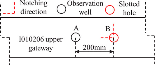
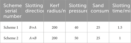
The layout of slotting test scheme is shown in Figure 5. On I010206 working face, the gateway is 300 m ahead of the working face to avoid the influence of mining. Slotting is carried out from hole B to hole A, and hole A is observation well, so as to determine lithol-ogy, adjust fracturing position and test the effect. When the kerf radius is 200 mm, the rela-tionship between kerf pressure and kerf time is determined, and the kerf is planned to be carried out in hole B in four sections to hole A with a spacing of 200 mm. This time, two schemes are designed to carry out slotting test analysis. In Scheme 1, the slotting direction is B→A, the slotting pressure is 40 MPa, so that the slotting hole can be slotted with the 200 mm rock stratum in observation well, and the slotting length is 300 mm. Record the slotting time and sand consumption, and move the slotting downwards. In Scheme 2, the kerf pressure is changed to 50 MPa, and other kerf parameters are consistent with Scheme 1.
The layout of fracturing test scheme is shown in Figure 6. There are 4 boreholes in the fracturing test, among which E and H boreholes are observation well, and F boreholes and I boreholes are slotting and fracturing boreholes. After the cutting and fracturing of the F hole and I hole, the internal conditions of the E hole and the H hole are detected, and the fracturing test results are analyzed accordingly. Using the determined parameters of abrasive kerf, the fracturing experiment after abrasive jet is further carried out to determine the fracturing radius.
In the first scheme, the cutting direction is F→E, the cutting radius is 200 mm, the cutting length is 300 mm, the sand consumption is 25 kg, and the fracturing pressure is 50 MPa. Based on this, the feasibility of 5 m fracturing radius is analyzed. In the second scheme, the cutting direction is F→E and the fracturing pressure is 60 MPa. Based on this, the feasibility of 5 m fracturing radius is analyzed. In the third scheme, the cutting direc-tion is I→H, and the fracturing pressure is 60 MPa. Based on this, the feasibility of 10 m fracturing radius is analyzed. The remaining parameters of Scheme 2 and Scheme 3 are consistent with those of Scheme 3.
4.2 Analysis of experimental results of axial topcutting of scrubbing jet
During the slotting test, slotting was conducted from the position of hole B at 17 m to the direction of hole A at a distance of 200 mm. The pressure of water injection pump was 40 MPa, the amount of sand added was 25 kg, the slotting length was 300 mm, the slotting duration was 1.5 min, the rock stratum at a distance of 200 mm between holes A and B was cut, and water came out from hole A. From the 15 m position of hole B, cut the seam in the direction of hole A with an interval of 200 mm. The water injection pump gives a pressure of 50 MPa, the sand addition is 25 kg, the length of the seam is 300 mm, and the length of the seam is 1 min. Cut through the rock strata with an interval of 200 mm between holes A and B, and the water comes out of hole A.
The main parameters such as kerf radius, kerf pressure, kerf time and sand consump-tion are determined through experiments, as shown in Table 2.
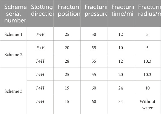
Based on the experimental study of fracturing radius parameters of two sections of hole F with 5 m, the fracturing radius of two sections with 5 m was successfully completed. Its kerf length is 300 mm, kerf radius is 200 mm, and kerf pressure is 40–55 MPa. The frac-turing parameters include fracture initiation pressure of 50–55 MPa, fracturing time of 10–12 min and fracturing radius of 5 m.
According to the experimental study on the parameters of fracturing radius of I hole in four stages of 10 m, the fracturing radius of 10 m for three times was successfully com-pleted. Its kerf length is 500 mm, kerf radius is 200 mm, and kerf pressure is 40–55 MPa. The fracturing parameters include fracture initiation pressure of 55–60 MPa, fracturing time of 10–20 min and fracturing radius of 10–20 m. The test results are shown in Table 3.
As the kerf radius increases from 5 to 10 m, the fracturing pressure increases accordingly. The results show that higher pressure is needed to overcome the fracture strength and friction of rock in order to reach a longer crack propagation radius, thus promoting the crack to extend further. At the same time, when the fracturing pressure is 55 MPa, the fracturing time to reach the fracturing radius of 5 and 10.3 m is 10 and 24 min respectively. The fracturing time is significantly prolonged with the increase of fracture radius, which reflects the gradual accumulation and release of energy in the process of fracture propagation and the longer time required for a larger fracture volume to form stably. Through industrial experimental study, the main parameters of kerf depth of 200 m and kerf length of 300 m are determined as follows: kerf pressure of 40–50 MPa, sand con-sumption of 25 kg and kerf time of 1–1.5 min. By determining the main parameters of kerf, the fracturing pressure is 50–55 MPa with a kerf radius of 5 m and the fracturing time is 10–12 min, and the fracturing pressure is 55–60 MPa with a kerf radius of 10 m and the frac-turing time is 20–24 min.
5 Practice of axial top cutting and scour prevention of frosted jet
5.1 I010206 partition scour prevention scheme for working face
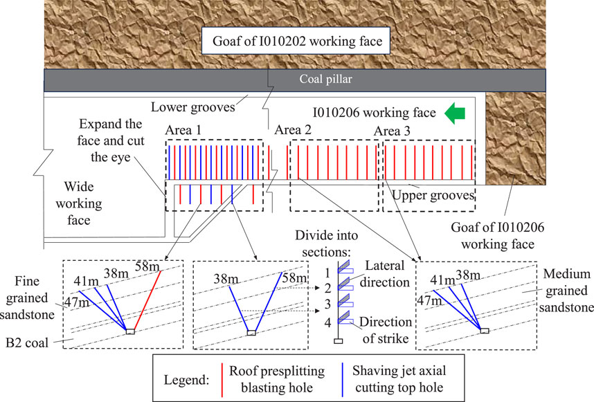
In the process of mine production, roof control measures are taken to prevent scour. According to the impact risk evaluation results of the working face, that is, area I, with a mileage of 690–790 m, is a strong impact risk area, area II, with a mileage of 930–1,030 m, is a medium impact risk area, and area III, with a mileage of 1030–1,130 m, is a medium impact risk area. The area I mainly adopts the methods of axial cutting and blasting presplitting of frosted jet to control the roof, while the area II and area III adopt the traditional blasting presplitting method to control the roof. The layout of the upper partition scour prevention scheme of I010206 working face is shown in Figure 7.
According to the results of field test parameters, the designed kerf pressure is 50–55 MPa, kerf time is 3–5 min, sand content is 25 kg, and kerf length is 300–500 mm. The cutting direction is strike direction to cut off the connection with goaf, and the inclined direction is tangent to the lateral roof. The fracturing pressure used this time is 50–65 MPa, the fracturing time is 15–20 min, and each hole is designed to be divided into four sections.
The main parameters of roof blasting presplitting in area I are that four holes are fan-shaped perpendicular to the center line of roadway. The drilling length is 47, 41, 38, and 58 m respectively, the inclination angles are 39, 52, 66 and 65 respectively, and the charge density is 2.75 kg/m. The main parameters of roof blasting presplitting in areas II and III are fan-shaped with three holes perpendicular to the center line of the roadway. The drilling length is 47, 41, and 38 m respectively, the inclination angles are 39, 52 and 66 respectively, and the charge density is 2.75 kg/m. Three-stage emulsion explosive, instant detonator and forward charging are used, and the connection mode is parallel connection in the hole and series connection outside the hole.
5.2 Implementation process of axial topcutting project of scrubbing jet
During the implementation of axial roof cutting by abrasive jet, the data of hydraulic pressure gauge and the on-site slotting and fracturing process are used for control. The typical abrasive jet curve is taken to analyze the implementation process, and its sectional slotting and fracturing curves are shown in Figure 8. Through the monitoring data of hydraulic pressure instrument, it can be clearly seen that the single-stage process includes three processes: pipeline testing and pressure testing, slotting and fracturing. The main purpose of pipeline testing and pressure testing is to check whether the pipeline is normal and to judge the primary fracture of rock stratum. The cutting and fracturing process is controlled on site according to the main design parameters and the field observation of water production, and 4 stages of fracturing are designed for each hole. The operation process of other sections is mainly the process of circular cutting, judging primary cracks and fracturing. Then, enter the circulation of the next hole.
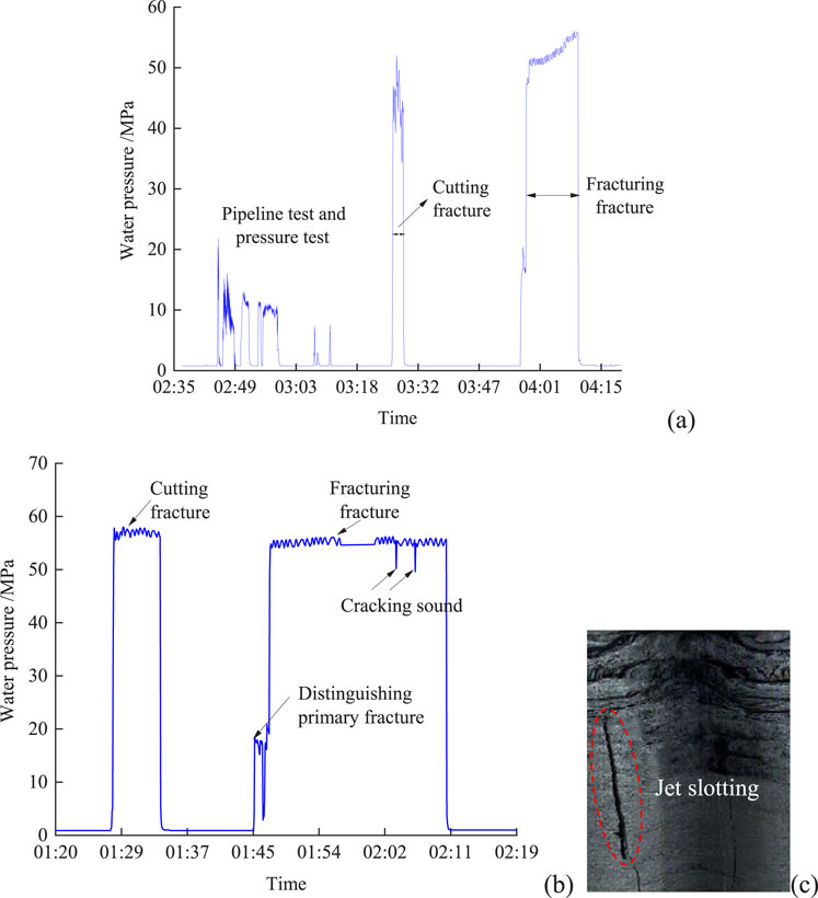
Figure 8. Sectional slotting and fracturing curve. (A) typical curve of the first section of a hole; (B) typical curve of other sections of a hole; (C) fracture hole peep diagram.
After the completion of the process, the drilling peep is used to observe the propagation of kerf and fracturing cracks in the hole, and the kerf and fracture can be displayed intuitively through the peep. Through strict on-site supervision, on-site monitoring and observation, the application of abrasive jet axial roof cutting technology in hard roof control and scour prevention of I010206 working face was completed.
5.3 Inspection of scour prevention effect in mining process of working face
Microseismic monitoring can monitor the time, space and energy of coal and rock fracture events during mining. Therefore, firstly, the anti-scour effect of mining face is an-alyzed through microseismic monitoring and analysis.
The microseismic monitoring results of different zones are shown in Figure 9. The results of microseismic monitoring show that the distribution range of microseismic events in area I is mainly 200 m ahead of the working face, and the peak distribution area is 130 m ahead of the working face. The distribution range of microseismic events in Area II is mainly 200 m ahead of the working face, and the peak distribution area is 80 m ahead of the working face. The distribution range of microseismic events in area I is mainly 200 m ahead of the working face, and the peak area of concentrated distribution is 80 m ahead of the working face.
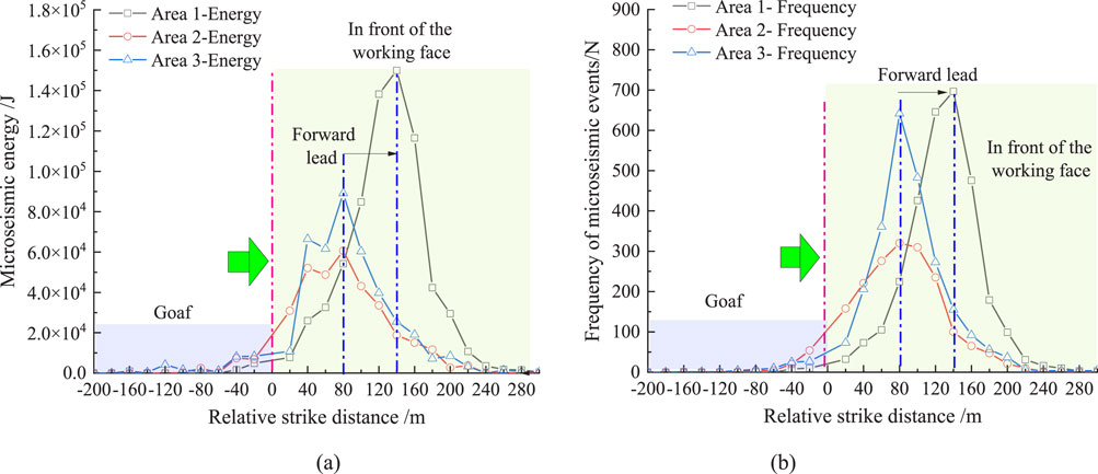
Figure 9. The microseismic monitoring results of different zones. (A) comparison of energy advance distribution of microseismic events; (B) comparison of frequency advance distribution of microseismic events.
According to the monitoring results of microseisms, the statistical table of average en-ergy-cumulative frequency of microseisms in different areas is summarized as shown in Table 4. The average released energy of area I is 137.64 J, which is about 10% lower than that of area II and 52.4% lower than that of area III. There were 1998 microseismic events in area I, which was about 20% higher than that in area II and 34.5% higher than that in area III. Compared with the traditional blasting presplitting area, the concentrated distribution of microseismic events in the roof combination presplitting area I shifts to the front away from the working face, which makes the rock activity far away from the stope operation area. The safety of operators in the mining influence range is increased. Advance promotes the energy release of surrounding rock, and releases it with small energy. It reduces the ac-tivity intensity of surrounding rock and weakens the dynamic load effect of impact danger.
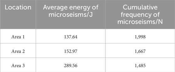
Table 4. The statistical table of average energy-cumulative frequency of microseisms in different areas is summarized.
5.4 Support pressure monitoring and analysis
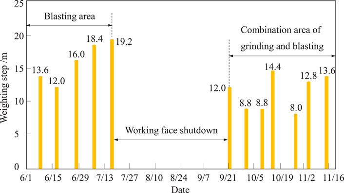
The greater the periodic weighting step of roof strata, the stronger the dynamic load, and the higher the possibility of inducing impact danger. According to the monitoring re-sults of the support pressure, the comparison chart of periodic weighting is drawn as shown in Figure 10. In the process of working face mining, combined with the field caving observation, it shows that the hard roof can collapse in time. The combination of axial roof cutting with abrasive jet and blasting presplitting can effectively weaken the intact hard rock stratum of the roof and avoid large-scale rock stratum collapse. Compared with the blasting area only, the weighting step under the combined mode of axial cutting of abra-sive jet and blasting presplitting is reduced. The optimization of pressure relief mode effec-tively improves the working condition of hydraulic support, and the periodic weighting step is reduced from 12.0∼19.2 m to 8.0∼14.4 m, which provides a new method for the treatment of hard roof erosion in the later stage of mine. The average periodic weighting step is reduced from 15.84 to 11.20 m, with a reduction rate of 29.29%.
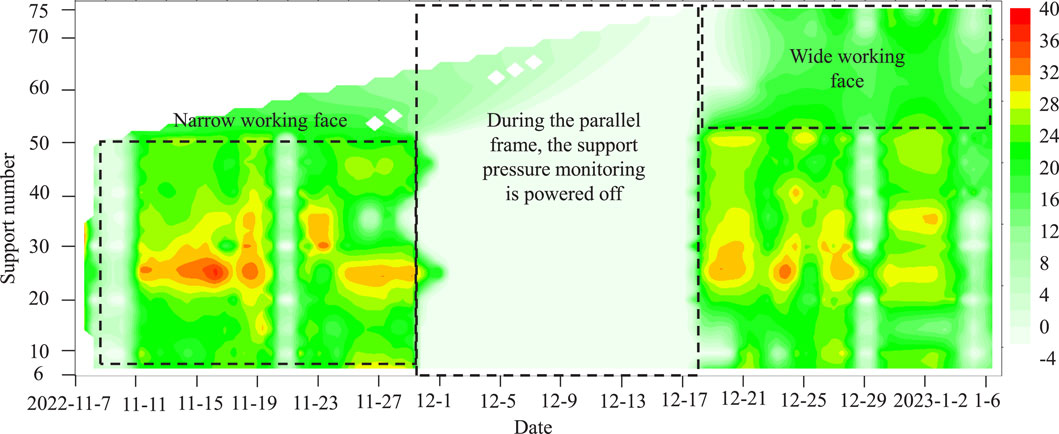
Strong rock movement is the main cause of impact danger during initial mining, and the cloud map of support pressure distribution in working face is shown in Figure 11. In the process of working face mining, combined with field caving observation, it shows that the hard roof can collapse in time, and the axial cutting of abrasive jet can effectively weaken the complete hard rock layer of the roof. Thus, large-scale rock caving is avoided, and the expanded non-abrasive jet area is larger, which effectively improves the working conditions of the hydraulic support. Therefore, the effect of the roof on the coal wall of the working face in the axial roof cutting area of the abrasive jet is obviously improved, which realizes the effect of the first roof caving compared with the traditional blasting, and pro-vides an effective new method for the treatment of the hard roof in the later stage of the mine.
5.5 Measurement and analysis of coal body stress
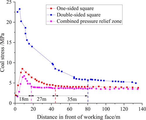
In order to further control the impact hazard, through the measurement of coal stress, the static load control effect and stress level of the working face after taking measures are analyzed. Because area I is a dangerous area of strong impact, it is treated by increasing the axial cutting top hole of frosted jet because of the distance between the pre-splitting holes of area II and area III measures. On the other hand, the layout distance of pre-splitting holes in single-sided square and double-sided square area blasting is the same as that in area I, only in the axial cutting of frosted jet and blasting pre-splitting mode.
For this reason, a comparative analysis is made between the area I with combined pressure relief and the measured area of static load of coal with one-sided square and double-sided square with blasting presplitting. The measured results of coal stress moni-toring are shown in Figure 12. The significant influence range of coal static load in area I is 20 m, the peak value is 8–10 m, and the stress concentration factor is 1.68. The significant influence range of static load on one side square area is 45 m, the peak value is 8–10 m in the leading face, and the stress concentration factor is 2. The significant influence range of static load in the double-sided square area is 80 m in the leading face, the peak value is 8–10 m in the leading face, and the stress concentration factor is 4.4. Compared with the traditional blasting pre-splitting area, the influence range of the leading abutment pres-sure in the blasting combined pre-splitting area is greatly reduced, and the stress concen-tration factor is obviously reduced, thus achieving a good effect of coal static load control in the combined pre-splitting area.
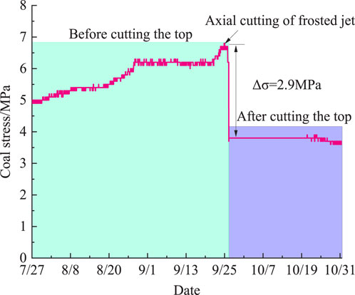
The stress change curve of coal before and after fracturing is shown in Figure 13. After the width of the working face increases, the coal stress curve is measured at the 5 m posi-tion of the upper trough leading working face. After the axial cutting of the frosted jet, the stress concentration of the coal body gets a rapid response, and the stress of the coal body has an obvious stress drop, reaching 2.9 MPa. After the axial cutting of the frosted jet, the stress concentration of the coal body gets a rapid response, and the stress of the coal body drops obviously, and the maximum reduction of the stress reaches 2.9 MPa, with a decrease of about 41.85%. During the mining period of face expansion, the stress concentration of coal has been significantly improved. Under the influence of mining, the stress concentration of coal body in the axial cutting area of frosted jet does not increase again, which has a good effect of pressure relief of coal body.
Based on the combination of frosted jet axial roof cutting and roof deep-hole pre-splitting blasting, the prevention and control of rock burst in I010206 working face is car-ried out. The construction management and control of the new technology of frosted jet axial roof cutting and the analysis of anti-scour effect in the mining process are realized. The anti-scour practice shows that the control effect of dynamic and static load is good, the strong impact dangerous area mentioned above is safely pushed over and the mine safety production is realized.
6 Conclusion
(1) The main contents of this paper are as follows: (1) through the analysis of hard roof frosted jet axial cutting and anti-scour test, the key technical parameters of hard roof frosted jet axial cutting suitable for Kuangou Coal Mine are determined. The slotting test results show that the slotting depth is 200 m, the slotting length is 300 m, the slotting pres-sure is 40–50 MPa, the sand consumption is 25 kg, and the slotting time is 1–1.5 min. The fracturing pressure of 50–60 MPa and the fracturing time of 20–24 min are obtained by axial topping of frosted water jet.
(2) After the implementation of the new technology of frosted jet axial roof cutting, the cracks in the roof strata are produced and expanded effectively after slotting and fractur-ing, and the cracks break during the fracturing period, and the crack extends in the range of 10–20 m, which destroys the integrity of the roof. The periodic pressure step distance de-creased obviously, the pressure step distance decreased from 12.0 ∼ 19.2 m to 8.0 ∼ 14.4 m, the influence range of mining stress and stress concentration factor decreased obviously, and the activity strength and dynamic load effect of surrounding rock decreased obvious-ly.
(3) Compared with the traditional blasting roof cutting technology, after the combined treatment of frosted jet axial cutting and blasting, the concentration area of microseismic events during mining is transferred from 80 to 130 m. After the axial cutting of the frosted jet, the stress concentration of the coal body gets a rapid response, and the stress of the coal body has an obvious stress drop, reaching 2.9 MPa. The energy release of microearthquakes is mainly small energy events, which achieves a good anti-erosion effect.
Data availability statement
The raw data supporting the conclusions of this article will be made available by the authors, without undue reservation.
Author contributions
RS: Methodology, Writing–original draft, Funding acquisition, Project administration, Resources, Software, Supervision, Validation, Visualization. ZZ: Conceptualization, Writing–review and editing. WY: Data curation, Writing–original draft. HL: Formal Analysis, Investigation, Writing–original draft.
Funding
The author(s) declare that financial support was received for the research, authorship, and/or publication of this article. This work was supported by the National Natural Science Foundation of China [grant number 51874231].
Conflict of interest
Author RS was employed by Tiandi Science and Technology Co., Ltd. Authors ZZ, WY, and HL were employed by Xinjiang Energy Co., Ltd., CHN Energy.
Publisher’s note
All claims expressed in this article are solely those of the authors and do not necessarily represent those of their affiliated organizations, or those of the publisher, the editors and the reviewers. Any product that may be evaluated in this article, or claim that may be made by its manufacturer, is not guaranteed or endorsed by the publisher.
References
Abe, A., Kim, T. W., and Home, P. A. (2021). Laboratory hydraulic stimulation experiments to investigate the interaction between newly formed and preexisting fractures. Int. J. Rock Mech. Min. Sci. 141, 104665. doi:10.1016/j.ijrmms.2021.104665
Cruz, F., Roehl, D., and Vargas, E. A. V. (2018). An XFEM element to model intersections between hydraulic and natural fractures in porous rocks. Int. J. Rock Mech. Min. Sci. 112, 385–397. doi:10.1016/j.ijrmms.2018.10.001
Dehghan, A. N., Goshtasbi, K., Ahangari, K., and Jin, Y. (2018). The effect of natural fracture dip and strike on hydraulic fracture propagation. Int. J. Rock Mech. and Min. Sci. 171, 422–430. doi:10.1016/j.ijrmms.2015.02.001
Dehghan, A. N. (2020). An experimental investigation into the influence of pre-existingnatural fracture on the behavior and length of propagatinghydraulic fracture. Eng. Fract. Mech. 107330 (240), 107330–107414. doi:10.1016/j.engfracmech.2020.107330
Feng, C., Chong, J., Xingping, L., Jianqiang, C., Suilin, Z., and Shifeng, H. (2022). Study on advancing rate of steeply inclined extra-thick coal seam in rock burst mine based on loading-unloading response ratio. J. China Coal Soc. 47 (2), 745–761.
Feng, X. C. (2012). Study on the Theory and experiment of hard-brittle materials with high-pressure AWJ cutting. Harbin, Heilongjiang: Harbin University of Science and Technology.
Ghaderi, A., Shakib, J. T., and Nik, M. A. S. (2018). The distinct element method (DEM) and the extended finite element method (XFEM) application for analysis of interaction between hydraulic and natural fractures. J. Petroleum Sci. Eng. 171, 422–430. doi:10.1016/j.petrol.2018.06.083
He, Q. Y., Suorineni, F. T., Ma, T. H., and Oh, J. (2017). Effect of discontinuity stress shadows on hydraulic fracture re-orientation. ternational J. Rock Mech. and Min. Sci. 91, 179–194. doi:10.1016/j.ijrmms.2016.11.021
Heng, S., Liu, X., Li, X. Z., Zhang, X., and Yang, C. (2019). Experimental and numerical study on the non-planar propagation of hydraulic fractures in shale. J. Petroleum Sci. Eng. 179, 410–426. doi:10.1016/j.petrol.2019.04.054
Irani, A. E., Azadi, A., Nikbakht, M., Azarafza, M., Hajialilue Bonab, M., and Behrooz Sarand, F. (2022). GIS-based settlement risk assessment and its effect on surface structures: a case study for the tabriz metro-line 1. Geotech. Geol. Eng. 40, 5081–5102. doi:10.1007/s10706-022-02201-x
Jia, C., Lai, X. P., Cui, F., Zhang, S., Sun, J., and Tian, M. (2022). Mechanism of rock burst and its dynamic control measures in extra-thick coal seam mining from below the residual coal seam to below the gob. Lithosphere 2022, 17. doi:10.2113/2022/8179501
Jia, C., Lai, X. P., Cui, F., Xu, H., Zhang, S., Li, Y., et al. (2024). Mining Pressure distribution lawand disaster prevention of isolated island working face under the condition of hard “umbrella arch”. Rock Mech. Rock Eng. 57, 8323–8341. doi:10.1007/s00603-024-03961-z
Junfeng, P., Wentao, M., Shaohong, L., and Jiaming, G. (2021). A prevention technology of rock burst based on directional presplitting of water jet prefabricated slot in hard roof. Chin. J. Rock Mech. Eng. 40 (8), 1591–1602. doi:10.13722/j.cnki.jrme.2020.1056
Junfeng, P., Hongpu, K., Yaodong, Y., Xiaohui, M., Wentao, M., Chuang, L., et al. (2023). The method, mechanism and application of preventing rock burst by artificial liberation layer of roof. J. China Coal Soc. 48 (02), 636–648.
Junzhe, Y., Kaige, Z., Zhenrong, W., and Naiyong, P. (2020). Technology of weakening and danger-breaking dynamic disasters by hard roof. J. China Coal Soc. 45 (10), 3371–3379. doi:10.13225/j.cnki.jccs.2020.0599
Hongpu, K., Yanjun, F., Zhen, Z., Kaikai, Z., and Peng, W. (2023). Hydraulic fracturing technology with directional boreholes for strata control in underground coal mines and its application. Coal Sci. Technol. 51 (01), 31–44. doi:10.13199/j.cnki.cst.2022-2004
Lai, X. P., Jia, C., Cui, F., Chen, J., Zhou, Y., Feng, G., et al. (2022). Microseismic energy distribution and impact risk analysis of complex heterogeneous spatial evolution of extra-thick layered strata. Scieitific Rep. 12, 10832. doi:10.1038/s41598-022-14538-7
Li, Z. H., Pan, Y. S., Zhang, X., Yin, L. L., Xia, Y. X., Ju, W. J., et al. (2009). Mechanism of releasing pressure by high-pressure water jet applied to cutting coal seam. J. Liaoning Tech. Univ. Sci. 28 (1), 43–45.
Liu, Z. Y., Chen, M., and Zhang, G. Q. (2014). Analysis of the influence of a natural fracture network on hydraulic fracture propagation in carbonate formations. Rock Mech. Rock Eng. 47, 575–587. doi:10.1007/s00603-013-0414-7
Pan, Y. S., Li, Z. H., and Zhang, M. T. (2003). Distribution type mechanism and prevention of rock brust in China. Chin. J. Rock Mech. Eng. 22 (11), 1844–1851.
Pan, J. F., Ning, Y., Mao, D. B., Lan, H., Du, T., and Peng, Y. (2012). Theory of rockburst start-up during coal mining. Chin. J. Rock Mech. Eng. 31 (3), 586–596.
Qin, M., Yang, D., Chen, W., and Yang, S. (2021). Hydraulic fracturing model of a layered rock mass based on peridynamics. Eng. Fract. Mech. 258, 108088. doi:10.1016/j.engfracmech.2021.108088
Taleghani, A. D., Gonzalez, M., and Shojaei, A. (2016). Overview of numerical models for interactions between hydraulic fractures and natural fractures: challenges and limitations. Comput. Geotechnics 71, 361–368. doi:10.1016/j.compgeo.2015.09.009
Weng, M. Y., Hao, Y. H., and Xie, J. H. (2019). Study on “drilling cutting-fracturing” integrated energy dissipation technology for hard coal rock mass. Coal Sci. Technol. 47 (8), 84–88.
Wu, H., Zhu, H. H., Zhang, C. C., Zhou, G. Y., Zhu, B., Zhang, W., et al. (2020). Strain integration-based soil shear displacement measurement using high-resolution strain sensing technology. Measurement 166, 108210. doi:10.1016/j.measurement.2020.108210
Wu, M. Y., Wang, W. S., Song, Z. L., Liu, B., and Feng, C. (2021). Exploring the influence of heterogeneity on hydraulic fracturing based on the combined finite-discrete method. Eng. Fract. Mech. 252, 107835. doi:10.1016/j.engfracmech.2021.107835
Xia, Y. X., Ju, W. J., Su, S. J., Lu, Q., Ding, G. L., Su, B., et al. (2020). Experimental study on hydraulic reaming of gutters in coal seam with impact pressure. J. Min. Strata Control Eng. 2 (1), 84–91.
Zhang, C. J., Du, T. T., Li, H. P., and Jia, B. B. (2019). Research on rock burst prevention of high static coal seam in hard roof working face. Coal Sci. Technol. 47 (3), 112–119.
Keywords: hard roof, rockburst, hydraulic fracturing, pressure relief regulation, axial fracture cutting and fracturing of abrasive jet
Citation: Sun R, Zhao Z, Yang W and Li H (2024) Research and application of hydraulic fracturing axial roof cutting technology for gently inclined hard roof based on abrasive jet. Front. Earth Sci. 12:1485210. doi: 10.3389/feart.2024.1485210
Received: 23 August 2024; Accepted: 07 October 2024;
Published: 30 October 2024.
Edited by:
Xiangli He, Ministry of Emergency Management, ChinaReviewed by:
Mohammad Azarafza, University of Tabriz, IranCun Zhang, China University of Mining and Technology, China
Copyright © 2024 Sun, Zhao, Yang and Li. This is an open-access article distributed under the terms of the Creative Commons Attribution License (CC BY). The use, distribution or reproduction in other forums is permitted, provided the original author(s) and the copyright owner(s) are credited and that the original publication in this journal is cited, in accordance with accepted academic practice. No use, distribution or reproduction is permitted which does not comply with these terms.
*Correspondence: Ruda Sun, dHNzdW5ydWRhQDE2My5jb20=
 Ruda Sun
 Zhipeng Zhao3