- 1China Railway Development and Investment Group Co., Ltd., Kunming, China
- 2NO.3 Construction Company of China Railway NO.10 Engineering Group Co., Ltd., Hefei, China
- 3School of Qilu Transportation, Shandong University, Jinan, China
The stability of the surrounding rock is an important engineering challenge for soft rock tunnels. Based on the FLAC3D finite difference numerical simulation software, this paper analyzes the typical area of the Fenghuang Mountain tunnel in the Chuxiong section of the Central Yunnan Water Diversion Project. Three construction methods are implemented: three-bench method, reserved core soil method, and CD method, with two excavation parameters being different lengths of the upper step and heights of the lower step. The whole excavation process of the red layer soft rock tunnel is simulated under four supporting conditions: different bolt lengths, different bolt spacings, different initial support thicknesses, and varying advanced grouting strengths. The results indicate that the CD method has a strong constraint on the vertical displacement of the surrounding rock at the arch, while the reserved core soil method has a better effect on controlling the uplift value, and the three-step method has a better constraint on the horizontal convergence of the surrounding rock at the arch waist. The increase in the distance between the upper and lower steps has a great influence on the horizontal convergence value of the tunnel, and the lower steps have a better inhibition effect on the horizontal convergence value of the surrounding rock at the tunnel arch. The increase in the lining thickness has a significant effect on restraining the deformation of the surrounding rock, and advanced grouting is efficient in enhancing the mechanical parameters of the surrounding rock and reducing the displacement of the surrounding rock. The support optimization engineering application is carried out in the 6# construction branch tunnel of the Fenghuang Mountain tunnel, yielding good results.
1 Introduction
The 21st century marks a new stage of underground space development and utilization in China and a new period of rapid development of tunnels and underground engineering (Cai et al., 2020; Cai et al., 2021; Cai et al., 2019; Fan H. et al., 2023; Fan et al., 2024; Fan H. Y. et al., 2023). The tunnel construction process faces various complex geological environments. The “Middle Yunnan Red Bed” is a kind of continental clastic sedimentary stratum with red appearance, mainly distributed in the Chuxiong, Yuanmou, and Dayao areas of Yunnan Province (Boonchai et al., 2020).The stability of the surrounding rock, caused by the expansion, disintegration, and softening of soft rock, is often encountered during tunnel construction in central Yunnan (Qian et al., 2020), leading to significant economic losses and casualties (Zhao et al., 2022).
Due to the particularity of the red-layer soft rock, many scholars and experts have studied its physical and mechanical properties, deformation, and instability modes in recent years (Bin et al., 2023; Cao et al., 2023; Dong et al., 2023; Guo et al., 2023; Jia et al., 2023; Jian et al., 2023; Kang et al., 2023; Liu et al., 2023; Wang et al., 2023; Zhao et al., 2023; Zhou et al., 2023). Chen et al. (2010); Feng et al. (2005); and He et al. (2019) studied the physical and mechanical properties of red-layer soft rock through relevant experiments, which provided a reference for the selection of parameters in numerical simulations and analytical calculations (Yuan et al., 2024). Wang et al. (2024) used a model test device for determining time-dependent characteristics of stress and deformation in weak surrounding rock and lining structures in operational tunnels, taking into account the influence of tunnel burial depth and the lateral pressure coefficient of the surrounding rock (Wang et al., 2024). The findings in Sun et al. (2024) indicate that the implementation of two-layer primary support can effectively mitigate the progression of large deformations in the weak surrounding rock; the sooner the primary support for the second layer is applied, the better the deformation control will be. Zhao H. G. et al. (2024) meticulously investigated the influence of the thickness of the weak interlayer on the mechanical response and failure behavior of the rock mass near the free surface of the tunnel, using a true triaxial test system. Zhu et al. (2024) showed that both shear failure and tensile failure are observed along joint surfaces, but shear failure is the main controlling factor for the peak strength of the rock mass with and without rockbolts. Energy-absorbing anchor supports have been used for the stability control of surrounding rocks to avoid engineering failures caused by large deformations in soft rocks (Li et al., 2023a). The deformation of the surrounding rock with different support parameters is predicted and analyzed using a neural network and a database formed by numerical simulation calculations (Li et al., 2023b). A new method combining directional and non-directional blasting techniques that reduces the subsidence of overlying strata above the gob has been proposed (Fu et al., 2024). The characteristics of a tunnel collapse deformation and its causal factors are analyzed as an example of a large deformation accident in a tunnel with granite residual soil in the surrounding rock (Huang et al., 2024). For tunnels with weak surrounding rocks, advanced support can be installed to reduce the unique release coefficient lambda (0) and the value of the constant D, for reducing the contact loads between the surrounding rock and primary support (Zhou et al., 2024). The results of Deng et al. (2024) indicate that the damage range was reduced by approximately 26%–64% compared to nongrouted rock. Advanced consolidation grouting can significantly improve the blasting explosion resistance of weak and broken rock masses. The in situ comprehensive investigation can provide early warnings of large deformations in the surrounding rock to ensure the safety and stability of the cavern (Zhao J. S. et al., 2024). The research by the abovementioned scholars on the construction control technology of large deformation tunnels in red-bed weak surrounding rocks in central Yunnan provides some theoretical support for the safe construction of tunnels, but the influence of construction parameters on the stability of the surrounding rock still poses a difficult problem in the engineering field. Therefore, it is urgent to study the optimization method of excavation parameters in the whole construction process of the tunnel.
In this paper, the typical tunnel section at a depth of 100 m in Fenghuangshan Tunnel of the Chuxiong section of water diversion in central Yunnan is studied. By using the finite difference numerical simulation software, three methods, namely, three-bench method, reserved core soil method, and CD method, are carried out, with the two excavation parameters being different upper bench lengths and different lower bench heights, and the whole excavation process of red-bed soft rock tunnels under four supporting conditions, different bolt lengths, different bolt spacings, different initial support thicknesses, and advanced grouting strengths, are simulated. The supporting effect of different supporting schemes and the limiting effect on the displacement of the surrounding rock are systematically analyzed, and the displacement variation law of the surrounding rock under different supporting conditions is obtained. It holds significant reference value for ensuring the safety of tunnel construction, optimizing the construction methods of soft rock tunnels, and serving the construction of soft rock tunnels in the water diversion project in central Yunnan.
2 Influence of the excavation method on the stability of the surrounding rock
2.1 Construction of the finite difference model
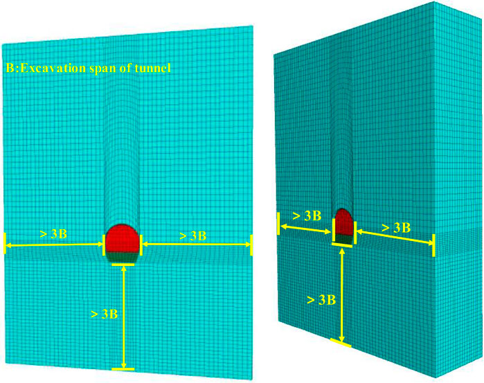
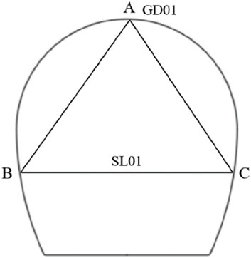
The tunnel model is established according to the design and construction drawing size of the Fenghuangshan Tunnel in the Chuxiong section of the Central Yunnan Water Diversion Project. The cross section of the exit tunnel of Fenghuang Mountain is horseshoe-shaped. The maximum span of the tunnel is 9.72 m, and the height is approximately 10.42 m. The overall model takes 50 m from the top of the tunnel to the top of the model. The model takes three times the maximum span to the left, right (X direction) and downward (Z direction), as shown in Figure 1.
Displacement boundary conditions are applied to the model, horizontal displacement constraints are applied to the model boundary, horizontal and vertical conditions are applied to the bottom, the top is the free boundary surrounding rock constitutive model M-C model, shell element simulation is used for shotcrete, pile element simulation for anchor rod, and eight-node hexahedron element is used for grid division. The tunnel excavation and support processes are simulated according to the actual construction method, which involves two steps. The timeliness of each step is not considered in the excavation process, and the excavation is carried out using a null simulation. The null model represents the material to be excavated and erased, and its status is automatically cleared when the module unit is given a NULL model, meaning it does not participate in subsequent calculations.
The total excavation length of the calculation model is 20 m, the height of the lower step is 2.7 m, the length of each cycle of the upper and lower steps is 1 m, and the stagger distance is 10 m. The initial support of the tunnel adopts a Bdk-type primary support section. Each section is equipped with 17 hollow grouting bolts with a diameter of 25 mm and a length of 6 m, which are installed around the excavation tunnel at an interval of 1 m according to the excavation. C20 concrete, with a thickness of 0.2 m, is selected as the shotcrete. The method of equivalent shotcrete is applied to the initial steel arch of the tunnel, as shown in the Formula 1:
where E* is the equivalent elastic modulus, EC is the elastic modulus of concrete, ES is the elastic modulus of the steel arch, AS is the cross-sectional area of the steel arch, and AC is the cross-sectional area of the initial shotcrete. The specifications for the I20b@50 I steel are a height of 200 mm, a width of 102 mm, and a flange thickness of 9 mm. The parameters for primary shotcrete, steel arch, and equivalent primary shotcrete are shown in Table 1 below.
The physical data of the surrounding rock are shown in Table 2.
The three-step excavation method, the core soil five-step excavation method, and the CD four-step excavation method are used for simulations.
2.2 Three-step excavation scheme
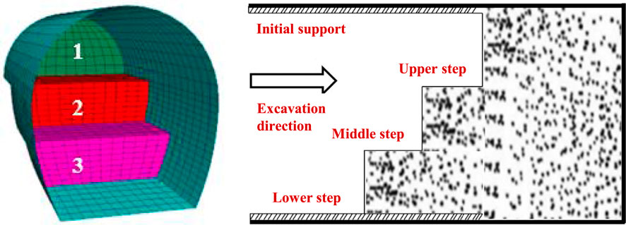
The three-step excavation method adopts the simultaneous excavation of the upper, middle, and lower steps and the symmetrical excavation of the left and right sides of the middle and lower steps; the inverted arch and the lower steps are treated as a whole, shortening the length of the steps and completing the initial support and sealing in time, as shown in Figure 2.
The three-step method is carried out through staggered excavation. One part is excavated first, two parts are excavated after the formation of the staggered distance, and three parts are excavated after the formation of the staggered distance, with excavation carried out for a total of 30 times. The vertical and horizontal converging displacements of the surrounding rock of the tunnel after excavation were recorded. The vertical and horizontal displacements of the surrounding rock after complete excavation are shown in Figure 3.
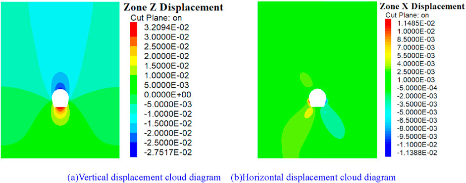
Figure 3. Displacement cloud diagram of the three-step excavation method. (A) Vertical displacement cloud diagram (B) Horizontal displacement cloud diagram.
As shown in Figure 3A, when the excavation method is changed to three-step excavation, the maximum subsidence of the arch surrounding rock at 10 m of the tunnel is 27.52 mm and the maximum uplift of the arch bottom surrounding rock is 32.09 mm. Compared with the arch bottom, the vertical displacement contour of the arch roof is sparse, indicating that the vertical displacement change rate of the surrounding rock of the arch is low at different depths, and the change rate decreases with the distance from the arch top. As shown in Figure 3B, the horizontal convergence value of the surrounding rock at the center of the straight wall of the tunnel reaches the maximum value, reaching 22.86 mm. The lateral horizontal displacement deformation of the tunnel is symmetrical, and the surrounding rock on both sides of the tunnel shows a similar change law. The horizontal displacement of the surrounding rock at the straight wall is distributed in a butterfly pattern and decreases from the circumference of the tunnel to the outside. The dark strip area appearing at the upper left of the tunnel has no obvious influence on the surrounding rock vault.
2.3 Five-step excavation scheme of reserved core soil
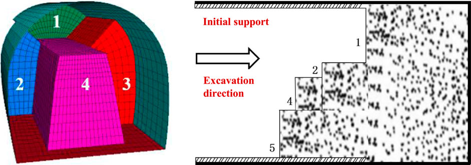
In the reserved core soil method, the upper half surface 1 is excavated first and lined in time; the left side area 2 is excavated after a misalignment is formed between the upper side and the part to be excavated on the left side; the left side area 3 is excavated after a misalignment is formed between the left side area 3 and the right side area 3; the core soil 4 is excavated after a misalignment is formed between the left side area 3 and the core soil 4. Invert 5 is excavated after all excavation is completed. The steps cycle 1m per cycle and the inverts advance 10 m per cycle, as shown in Figure 4.
The vertical and horizontal displacements of the surrounding rock of the tunnel after excavation were recorded. The cloud image of the vertical and horizontal displacements after full excavation is shown in Figure 5. The five-step excavation method of reserved core soil is carried out by means of staggered distances.
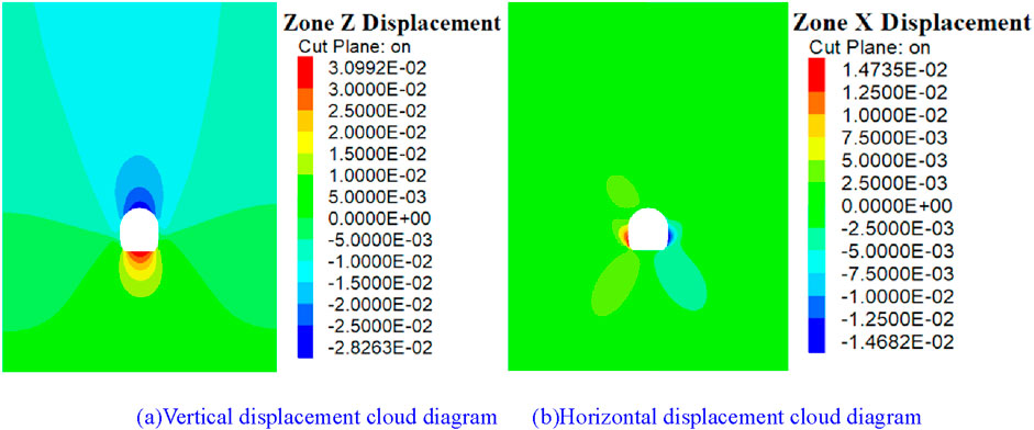
Figure 5. Displacement cloud diagram of the reserved core soil excavation method. (A) Vertical displacement cloud diagram. (B) Horizontal displacement cloud diagram.
Figure 5 shows that the vertical and horizontal distribution of the surrounding rock at 10 m in the tunnel is symmetrical after the tunnel is completely excavated. As shown in Figure 5A, the maximum vertical displacement of the surrounding rock of the tunnel appears at the bottom of the tunnel arch, approximately 30.99 mm, and the maximum value of the surrounding rock at the vault of the tunnel is 28.26 mm. The distribution of the vertical displacement contour of the surrounding rock is similar to that before, spreading outward in an oval shape, and the diffusion decreases. As shown in Figure (b), the maximum horizontal convergence displacement of the surrounding rock of the tunnel appears in the surrounding rock at the arch waist of the tunnel, with a size of 29.61 mm. There are four strip dark areas outside the tunnel, which are symmetrically distributed in four corners. The influence distance of horizontal displacement is small, and the diffusion range is limited. The surrounding rock at a long distance outside the tunnel is less disturbed, and the horizontal displacement of the surrounding rock is almost 0.
2.4 Four-step excavation scheme of the CD method
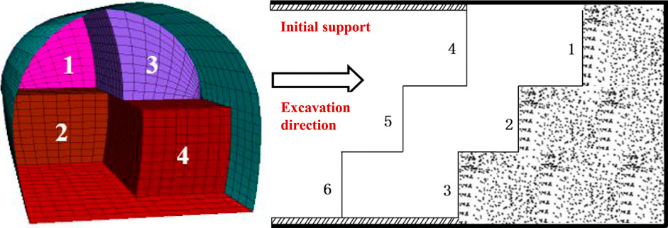
In the CD method, the excavation starts with the upper and middle steps on the left side in order, followed by the construction of the lining and the steel arch concrete to build the middle partition wall. Then, the upper and middle steps on the other side are excavated and supported in turn. Each excavation cycle covers 1 m. The internal steel frame and other structures are removed every 10 m each time. After the temporary support is removed, the excavation of parts 5 and 6 of the inverted arch is carried out in two stages, with each stage advancing 10 m, as shown in Figure 6.
The vertical and horizontal displacement nephograms of the surrounding rock of the tunnel are shown in Figure 7. The excavation of the CD method is carried out with staggered distances.
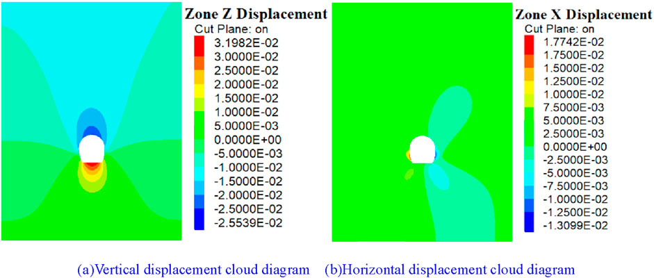
Figure 7. Displacement cloud diagram of the CD method. (A) Vertical displacement cloud diagram. (B) Horizontal displacement cloud diagram.
When the tunnel is excavated using the CD method, vertical and horizontal displacements of the surrounding rock are observed, as shown in Figure 7. As shown in Figure 7A, the influence range of tunnel excavation extends to the surface, approximately 55 m. The displacement contour line is asymmetric in the local area, with the deformation shifting to the left. The displacement contour line of the surrounding rock diffuses outward from the tunnel opening, with displacement values decreasing as the distance from the opening increases. The surrounding rock at the vault has the largest vertical settlement value, which is 25.54 mm, and the surrounding rock at the arch bottom has the largest rebound value, which is 31.98 mm. As shown in Figure 7B, the influence range of the horizontal displacement of the surrounding rock of the tunnel is limited, with the displacement values symmetrically distributed and the influence range forming a quadrangular pattern. The maximum horizontal displacement of the surrounding rock appears near the arch waist. The horizontal displacement of the left arch waist of the tunnel body is greater than that of the right, and the deformation range is similar. The maximum horizontal convergence value of the surrounding rock is 30.07 mm. The removal of the temporary support of the middle partition plate can easily cause secondary deformation of the surrounding rock of the tunnel. The displacement of the surrounding rock of the tunnel after excavation using the four different excavation methods is summarized in Table 3.
3 Influence of step parameters on the stability of the surrounding rock
3.1 Influence of upper bench length on the stability of the surrounding rock
Under the condition that other supporting parameters, excavation methods, and excavation parameters remain unchanged, the fault distances for the upper and lower steps are 6 m, 8 m, 10 m, 12 m, and 14 m, respectively, for numerical simulation calculations. Based on the numerical simulation results, the changes in vertical displacement of the surrounding rock at the tunnel arch’s top and bottom and the numerical value of horizontal displacement of the surrounding rock at the tunnel’s arch waist are analyzed.
The stagger distance of some upper and lower steps and the corresponding vertical and horizontal displacement nephograms of the surrounding rock are shown in Figure 8.
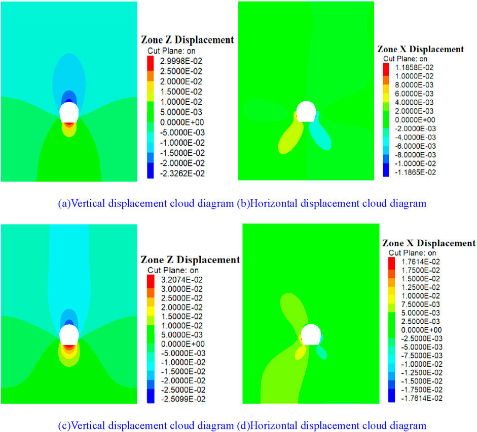
Figure 8. Displacement cloud diagram of the staggered surrounding rock of the upper and lower steps. (A, B) The stagger distance is 6 m; (C, D) The stagger distance is 14 m.
Figure 8 shows that the horizontal displacement of the surrounding rock of the tunnel is greater than its vertical displacement, which has a great influence on the horizontal displacement of the surrounding rock of the side wall. The horizontal displacement of the tunnel is symmetrically distributed, and the changes in the upper and lower steps have a certain degree of influence on the displacement of the surrounding rock. The variation curves of the vertical displacement of the surrounding rock at the vault of the tunnel and the horizontal displacement at the center of the side wall with the distance between the upper and lower steps are shown in Figure 9.
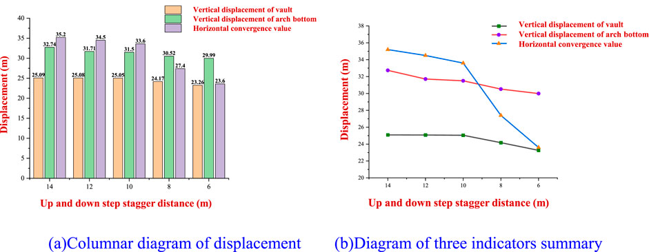
Figure 9. Diagram of surrounding rock displacement. (A) Columnar diagram of displacement. (B) Diagram of three indicators’ summary.
As shown in Figure 9A, when the stagger distance of the upper and lower steps increases from 6 m to 14 m, the influence of the change in the stagger distance of the upper and lower steps on the vertical displacement of the arch bottom is greater than that on the displacement of the surrounding rock at the vault of the tunnel. The whole curve also shows an obvious increasing pattern. With the increase in the stagger distance of the excavation, the growth rate of the vertical displacement at the arch bottom is first high, then slows down, and then high again. The vertical displacement of the surrounding rock increases, and the decrease in the stagger distance can inhibit the deformation of the surrounding rock. The horizontal convergence value of the tunnel also increases, with a large growth rate of up to 22.62%. It can be observed that with the increase in the staggered distance between the upper and lower steps, the tunnel has substantial ground stress, showing an obvious increasing trend, which, in turn, increases the displacement and deformation of the surrounding rock.
As shown in Figure 9B, with the decrease in the excavation distance between the upper and lower steps of the tunnel, the vertical displacement of the tunnel vault and the arch bottom and the horizontal convergence value of the tunnel decrease. Moreover, the reduction in the staggered distance between the upper and lower steps has a greater impact on the horizontal convergence value of the tunnel.
3.2 Influence of lower step height on the stability of the surrounding rock
Under the condition that other supporting parameters, excavation methods, and excavation parameters remain unchanged, the height of the lower step is determined to be 2.1 m, 2.4 m, 2.7 m, 3.0 m, and 3.3 m, respectively, for numerical simulation calculations. According to the numerical simulation results, the vertical displacement of the surrounding rock at the vault and bottom of the tunnel and the horizontal displacement of the surrounding rock at the haunch of the tunnel are analyzed.
The height of some lower steps and the corresponding vertical and horizontal displacement nephograms of the surrounding rock are shown in Figure 10.
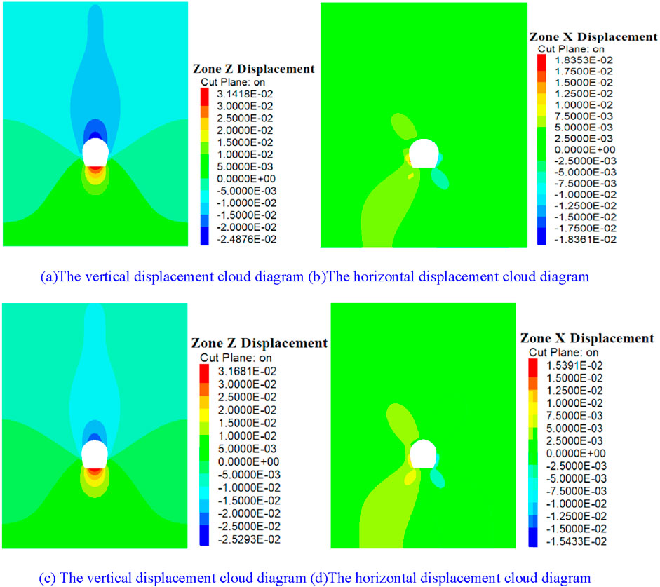
Figure 10. Cloud diagram of surrounding rock displacement. (A, B) The lower step height is 2.1 m. (C, D) The lower step height is 3.3 m.
Figure 10 shows that the influence range of tunnel excavation increases to a certain extent with the increase in the lower step. The uplift value of the arch bottom is greater than the sinking value of the arch crown, and the vertical displacement of the tunnel is less than the horizontal convergence displacement. The horizontal displacement cloud map of the tunnel still shows a butterfly-like distribution, and the divergence from the tunnel circumference to the outside is weakened. The curves of the vertical displacement of the surrounding rock at the vault of the tunnel and the horizontal displacement at the center of the side wall with the height of the lower step are shown in Figure 11:
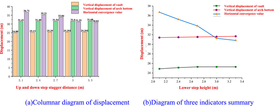
Figure 11. Diagram of surrounding rock displacement. (A) Columnar diagram of displacement. (B) Diagram of three indicators’ summary.
As shown in Figure 11A, during the excavation of the tunnel, the height of the lower step increases from 2.1 m to 3.3 m, and the vertical displacement of the arch bottom of the surrounding rock of the tunnel changes slowly, and the change range is smaller than the change value of the displacement of the surrounding rock of the vault. The influence of the change in the height of the lower step on the change of the arch bottom of the surrounding rock of the tunnel is almost negligible. The horizontal convergence value of the surrounding rock at the side wall of the tunnel shows a significant downward trend, with the growth rate initially increasing and then decreasing. Therefore, increasing the lower step height has a better inhibitory effect on the horizontal displacement of the surrounding rock at the arch waist of the tunnel, but excessively high lower steps will also hinder construction and reduce their inhibitory effects.
Figure 11B shows that during the process of tunnel excavation, the change in the height of the lower step of the tunnel has a weak influence on the vertical displacement of the vault and arch bottom of the surrounding rock of the tunnel, and the change range is within 1 mm, which has a great influence on the horizontal convergence displacement at the center of the side wall of the tunnel, and the overall curve shows a downward trend.
4 Influence of supporting structure parameters on the stability of the surrounding rock
4.1 Influence of bolt length on the stability of the surrounding rock
Under the condition that other supporting parameters, excavation methods, and excavation parameters remain unchanged, the length of the anchor rod is set to 5.0 m, 5.5 m, 6.0 m, 6.5 m, and 7.0 m, respectively, for numerical simulation calculations. According to the numerical simulation results, the vertical displacement of the surrounding rock at the tunnel vault and arch bottom and the horizontal displacement of the surrounding rock at the tunnel arch waist are analyzed. The length of some bolts and the corresponding vertical and horizontal displacement nephograms of the surrounding rock are shown in Figure 12.
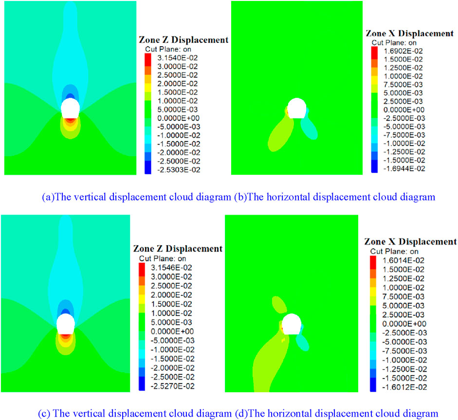
Figure 12. Cloud diagram of surrounding rock displacement. (A, B) The bolt length is 2.1 m. (C, D) The bolt length is 3.3 m.
As shown in Figure 12, the change in the length of the bolt has a weak influence on the diffusion range caused by the excavation of the surrounding rock. The vertical and horizontal displacement distribution contours of the surrounding rock are basically distributed in the same way, and the influence range of the excavation is basically the same. Because the soft rock of the red bed tunnel is weak and easy to break, the change in the length of the bolt leads to the displacement curve of the surrounding rock of the tunnel, as shown in Figure 13.
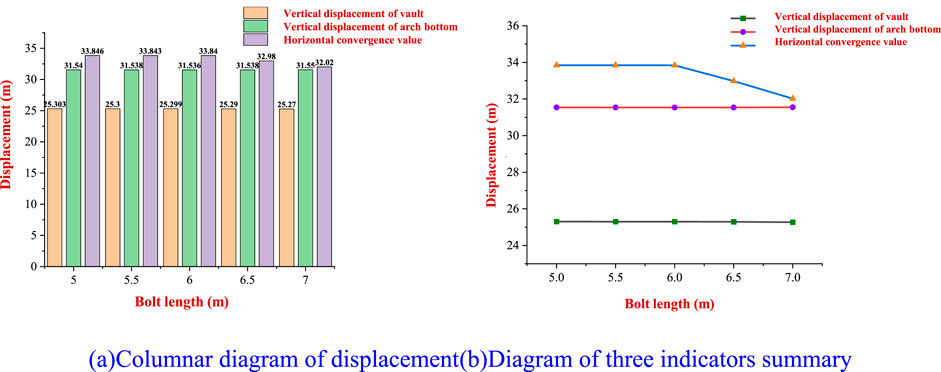
Figure 13. Diagram of surrounding rock displacement. (A) Columnar diagram of displacement. (B) Diagram of three indicators’ summary.
As shown in Figure 13A, when the length of the bolt increases from 5 m to 6 m, the horizontal convergence value of the surrounding rock at the center of the tunnel side wall does not decrease significantly. When the length of the bolt increases from 6 m to 7 m, the convergence value displacement decreases significantly, which is significantly greater than the vertical displacement of the surrounding rock at the arch bottom and the vault. Thus, it can be observed that due to the special mechanical properties of red-bed soft rock and the poor integrity of the surrounding rock of the tunnel, the increase in the length of the anchor rod in the tunnel has little effect on the vertical displacement of the surrounding rock at the vault and arch bottom. Only when the length of the anchor rod is increased to more than 6 m will the horizontal convergence limit of the displacement of the tunnel side wall be strengthened. Therefore, optimizing the length of the anchor is not an effective method for limiting the displacement of the surrounding rock.
Figure 13B shows that with the increase in the length of the tunnel bolt, the displacement of the surrounding rock at the center of the tunnel vault, arch bottom, and side wall initially remains stable and exhibits an almost constant trend. After the length of the bolt reaches 6 m, the three indicators begin to decline gradually. For the surrounding rock at the vault and the bottom of the arch, the decrease is almost negligible with the change in the length of the bolt. The horizontal convergence value of the surrounding rock of the tunnel decreases significantly after the length of the bolt reaches 6 m, and the inhibition effect of bolt length on the deformation of the side wall of the surrounding rock of the tunnel is enhanced. This is due to the poor integrity and strong fragmentation of the surrounding rock of the red-bed soft rock, and it is difficult for the bolt to be normally anchored to a complete rock, so the anchoring effect is limited.
4.2 Influence of bolt spacing on the stability of the surrounding rock
Under the condition that other supporting parameters, excavation methods, and excavation parameters remain unchanged, the bolt spacing is 0.5 m, 0.75 m, 1 m, 1.25 m, and 1.5 m, respectively, for numerical simulations. According to the numerical simulation results, the vertical displacement of the surrounding rock at the vault and the bottom of the tunnel and the horizontal displacement of the surrounding rock at the arch waist of the tunnel are analyzed.
Part of the bolt spacing and the corresponding vertical and horizontal displacement of the surrounding rock are shown in the following figures.
As shown in Figure 14, the change in bolt spacing will affect the influence range of tunnel deformation to a certain extent, and the appropriate reduction in bolt spacing will reduce the horizontal convergence value at the side wall of the tunnel. The change in the spacing of the supporting bolts leads to the change in the displacement of the surrounding rock of the tunnel, as shown in Figure 15.
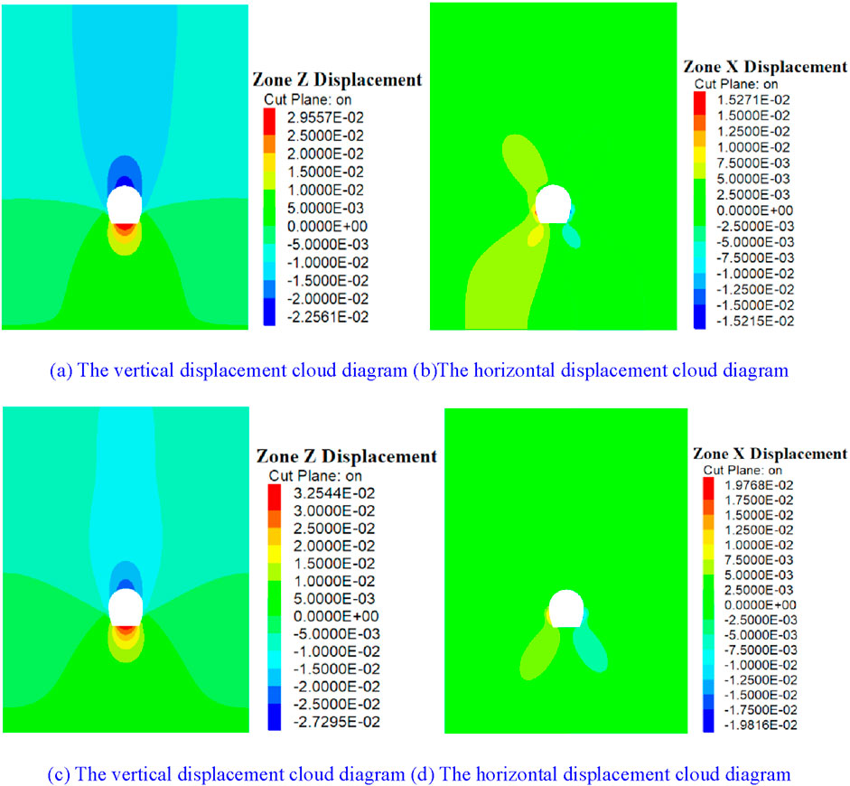
Figure 14. Cloud diagram of surrounding rock displacement. (A, B) The bolt spacing is 0.5 m. (C, D) The bolt spacing is 1.5 m.
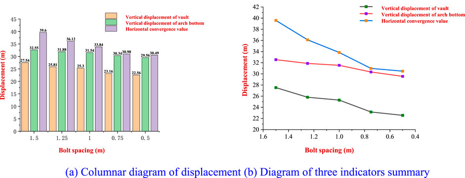
Figure 15. Diagram of surrounding rock displacement. (A) Columnar diagram of displacement. (B) Diagram of three indicators’ summary.
Figure 15A shows that reducing the bolt spacing within a certain range can control the horizontal convergence at the center of the side wall of the surrounding rock of the tunnel. However, as the bolt spacing continues to decrease, the limiting effect of the bolt decreases, and the effect of controlling the horizontal convergence value decreases. In the early stage, reducing the spacing of bolts and increasing the number of bolts strengthened the support and controlled the deformation of the surrounding rock to a certain extent. However, with the substantial increase in the number of bolts, excessively dense bolts destroyed the integrity of the surrounding rock and reduced the strength of the surrounding rock.
Figure 15B shows that the horizontal convergence of the surrounding rock at the center of the side wall of the tunnel is greater than the vertical displacement value at the arch bottom of the tunnel, which, in turn, is greater than the vertical displacement value at the vault of the tunnel. The change in bolt spacing has less influence on the vertical displacement of the surrounding rock than the horizontal convergence value at the arch waist of the tunnel, and the change range of both is less than 10 mm. The vertical displacement value and horizontal convergence value of the surrounding rock increase with the increase in bolt spacing and change synchronously. The influence of the change in bolt spacing on the horizontal convergence value of the surrounding rock at the center of the tunnel side wall is greater than that in the vertical displacement of the tunnel vault and arch bottom.
4.3 Influence of lining thickness on the stability of the surrounding rock
Under the condition that other supporting parameters, excavation methods, and excavation parameters remain unchanged, the initial lining thickness of the support is 10 cm, 15 cm, 20 cm, 25 cm, and 30 cm, respectively, for numerical simulation calculations. According to the numerical simulation results, the vertical displacement of the surrounding rock at the vault and arch bottom of the tunnel and the horizontal displacement of the surrounding rock at the arch waist of the tunnel are analyzed. The thickness change of some linings and the corresponding vertical and horizontal displacement nephograms of surrounding rock are shown in Figure 16.
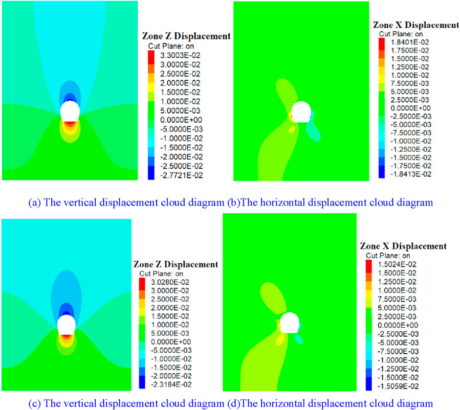
Figure 16. Cloud diagram of surrounding rock displacement. (A, B) The lining thickness is 10 cm. (C, D) The lining thickness is 30 m.
As shown in Figure 16, the change in lining thickness has a certain influence on the diffusion and distribution of vertical displacement of the surrounding rock of the tunnel. The increase in lining thickness will lead to an obvious decrease in vertical and horizontal convergence displacement of the surrounding rock of the tunnel. The change in the initial lining thickness of the tunnel leads to the change curve of the displacement of the surrounding rock of the tunnel, as shown in Figure 17.
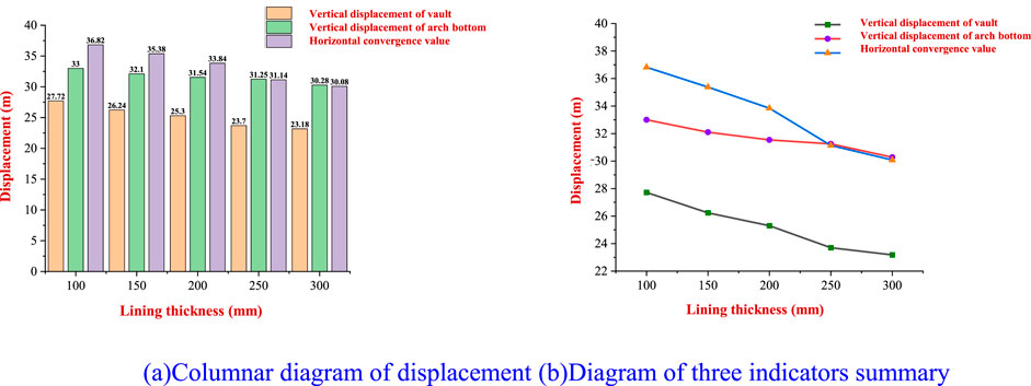
Figure 17. Diagram of surrounding rock displacement. (A) Columnar diagram of displacement. (B) Diagram of three indicators’ summary.
Figure 17A shows that the lining thickness has a significant effect on the displacement of the surrounding rock. When the lining thickness increases from 200 mm to 250 mm, the horizontal convergence value of the surrounding rock at the center of the side wall of the tunnel reaches 2.70 mm. Then, with the increase in lining thickness, the limiting effect on the surrounding rock begins to weaken. Although the substantial increase in the thickness of the lining can play a role in limiting the displacement of the surrounding rock, it will inevitably lead to concrete occupying the space originally belonging to the tunnel. Therefore, it is necessary to reasonably and scientifically control the thickness in the initial lining of the tunnel.
Figure 17B shows that the initial lining of the tunnel is the main component of the extrusion load. Increasing its thickness can improve its stiffness and can effectively limit the vertical and horizontal convergence displacement of the surrounding rock of the tunnel. With the gradual increase in the lining thickness, the vertical displacement of the surrounding rock at the vault and the bottom of the tunnel and the horizontal displacement at the side waist of the tunnel are greatly reduced.
4.4 Influence of advanced grouting on the stability of the surrounding rock
The strength of the surrounding rock is changed by advanced grouting, and the effect of different surrounding rock parameters on limiting the displacement of the surrounding rock is studied. Grouting of the surrounding rock can increase the cohesion of the surrounding rock by more than 2 to 3 times. This simulation adopts the method of improving the mechanical parameters of the surrounding rock in the advanced grouting reinforcement section. Under the condition that other supporting parameters and excavation methods remain unchanged, the mechanical strength of the surrounding rock is increased by 1.5 times and 2 times, respectively, and the displacement of the tunnel surrounding rock is analyzed according to the calculation results.
After advanced grouting, the vertical and horizontal displacement contours of the surrounding rock in the tunnel are shown in Figure 18
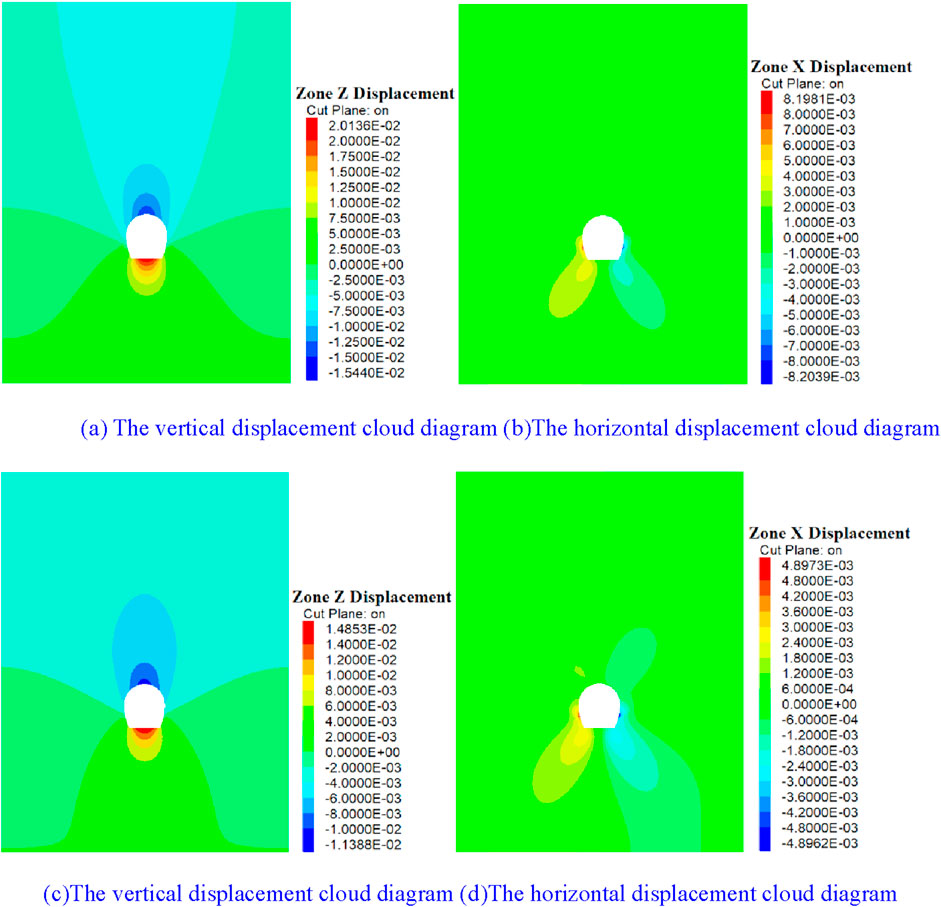
Figure 18. Cloud diagram of surrounding rock displacement. (A, B) The mechanical strength of the surrounding rock is increased by 1.5 times. (C, D) The mechanical strength of the surrounding rock is increased by 2 times.
As shown in Figure 18, advanced grouting is very effective in limiting the displacement of the surrounding rock of the tunnel. Advanced grouting in the rear area of the tunnel face during tunnel excavation can greatly reduce the vertical and horizontal displacement of the surrounding rock of the tunnel. The displacement statistics of the surrounding rock of the tunnel under different surrounding rock parameters are shown in Figure 19.
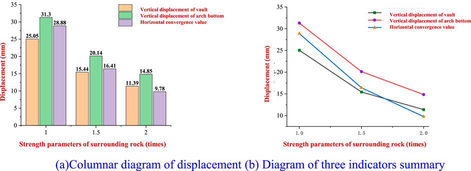
Figure 19. Diagram of surrounding rock displacement. (A) Columnar diagram of displacement. (B) Diagram of three indicators’ summary.
Figure 19 shows that the advanced grouting process of the surrounding rock of the tunnel can effectively control the vertical and horizontal convergence displacements of the surrounding rock. When the surrounding rock parameters are increased to 1.5 times the original values, the uplift value at the vault is reduced by 36.36%, the uplift value at the arch bottom is reduced by 35.65%, and the horizontal convergence value is reduced by 43.18%. After the strength of the surrounding rock increases from 1.5 times to 2 times, the restriction effect on the displacement of the surrounding rock decreases, and the decrease in the vault, arch bottom, and horizontal convergence value is 26.23%, 26.27%, and 40.40%, respectively. Due to the low cohesion and rock strength of red-bed soft rock, it is very feasible to limit the displacement of the surrounding rock through advanced grouting reinforcement.
5 Field test study
Monitoring points are arranged at the two sections: CX98 + 685 and CX98 + 695, in the 6 # branch tunnel of the Fenghuangshan Tunnel in the 6 # branch tunnel of the Chuxiong section of the Central Yunnan Water Diversion Project, and one section is used as the control group. The construction scheme is carried out according to the original construction scheme at the CX98 + 670 mileage section; the other section is used as the test section. The test section adopts the optimized method of increasing the thickness of the lining and advancing the grouting of the tunnel face. In the range of 120° of the vault, the displacement of the surrounding rock of the tunnel is limited by the spacing of 4.5 m for the small ducts of 40 cm and grouting reinforcement, with the thickness of the lining increased to 300 mm. The layout of monitoring points for vault subsidence and clearance convergence is shown in Figure 20.
5.1 Arch top subsidence detection
The displacement of the surrounding rock at the vault is monitored using a high-precision total station, and the control effect of surrounding rock displacement after optimization of supporting measures is assessed by analyzing the change trends and displacement value of two sections. The change in the vertical displacement value of the surrounding rock at the vault of control and test sections over time is shown in Figure 21.
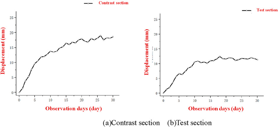
Figure 21. The displacement value of the two sections changes with time. (A) Contrast section. (B) Test section.
5.2 Clearance convergence value monitoring
The horizontal convergence displacement of the surrounding rock at the arch waist is monitored using a the high-precision total station, and the control effect of the surrounding rock displacement after the optimization of the support measures is assessed by analyzing the change trends of the clearance convergence value of the two sections and the displacement value. The change in the vertical displacement value of the surrounding rock at the vault of the control and test sections with time is shown in Figures 21, 22.
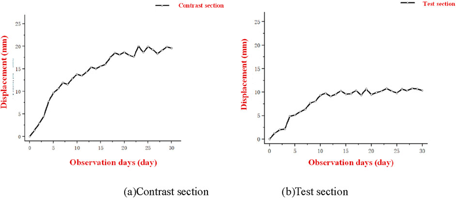
Figure 22. The displacement value of the two sections changes with time. (A) Contrast section. (B) Test section.
By increasing the thickness of the initial support and pre-grouting the rock in front of the face, the convergence value of tunnel clearance is reduced by approximately 8 ∼ 9 mm, representing a year-on-year decrease of 46.01%, and the horizontal displacement of the surrounding rock is effectively limited. Moreover, the time required for the surrounding rock to achieve overall stability is also advanced by approximately 7 days. As a result, the surrounding rock of the tunnel becomes more stable, and its displacement is effectively controlled.
6 Conclusion
In this paper, the FLAC3D numerical simulation software is used to simulate the whole process of tunnel excavation by changing the excavation methods, excavation parameters, and optimization methods of the supporting structure in the typical area of the Fenghuangshan Tunnel in the Chuxiong section of central Yunnan. The vertical and horizontal surrounding rock displacements of the tunnel under different excavation methods, excavation parameters, and supporting structures are studied. The results of this study are as follows:
(1) The excavation method has different effects on the displacement of the surrounding rock of the tunnel. The CD method has a strong constraint on the vertical displacement of the surrounding rock at the vault, and the deformation of the surrounding rock is effectively suppressed. The displacement of the surrounding rock at the bottom of the arch is similar to the deformation of the three methods, and the effect of the reserved core soil method to control the uplift value is slightly better. The three-bench method is relatively less disturbed to the surrounding rock and has a good constraint effect on the horizontal convergence of the surrounding rock at the arch waist.
(2) The influence of excavation parameters on the displacement of the surrounding rock of the tunnel: when the staggered distance between the upper and lower steps increases, the three displacement indexes of the tunnel increase an obvious manner, and the increase in the distance between the upper and lower steps has a great influence on the horizontal convergence value of the tunnel. The height of the lower step has little effect on the vertical displacement of the surrounding rock, and almost no change occurs, but it has a good inhibitory effect on the horizontal convergence value of the surrounding rock at the arch waist of the tunnel. With the increase in the height of the lower step, the horizontal convergence value decreases, but the height of the lower step cannot be excessively increased; otherwise, it will affect the construction process.
(3) The influence of the change in the supporting structure on the displacement of the surrounding rock of the tunnel: due to the weak and broken physical and mechanical properties of the red-bed soft rock, the influence of the length of the bolt on the limited displacement is weak. Only when the length of the bolt reaches more than 6 m, the horizontal displacement of the surrounding rock will be strengthened. In the early stage, reducing the spacing of anchor rods and increasing the number of anchor rods played a role in strengthening support and controlling the deformation of the surrounding rock to a certain extent. However, with the substantial increase in the number of anchor rods, excessively dense anchor rods can compromise the integrity of the surrounding rock, reduce its strength, and limit its displacement. The increase in lining thickness has a significant effect on restraining the deformation of the surrounding rock, but it cannot be increased without limit. It is a very efficient method to enhance the mechanical parameters of the surrounding rock and reduce its displacement through advanced grouting. The displacement of the surrounding rock is greatly limited after its parameters become 1.5 times the original. As the parameters continue to increase, their limiting effect will also diminish.
(4) In the field, the control and test sections are set up to carry out the test. The reflectors and high-precision total stations are arranged at three points of the tunnel to monitor the settlement of the surrounding rock vault and the convergence value of the tunnel clearance. By comparing the deformation trend and deformation value of the surrounding rock in the two sets of sections, it is concluded that thickening the lining and advancing grouting can effectively control the deformation of the surrounding rock.
Data availability statement
The original contributions presented in the study are included in the article/supplementary material; further inquiries can be directed to the corresponding author.
Author contributions
JL: writing–original draft, investigation, and software. SH: writing–original draft, formal analysis, and writing–review and editing. YX: writing–original draft, methodology, and project administration. YC: methodology and writing–review and editing. QN: software, visualization, and writing–original draft.
Funding
The author(s) declare that financial support was received for the research, authorship, and/or publication of this article. This study was funded by the Research and Development Program of China Railway Group Limited (No. 2020-Zhongdazhuanxiang-04).
Conflict of interest
Authors JL and YX were employed by China Railway Development and Investment Group Co., Ltd. Authors SH and QN were employed by NO.3 Construction Company of China Railway NO.10 Engineering Group Co., Ltd.
The remaining author declares that the research was conducted in the absence of any commercial or financial relationships that could be construed as a potential conflict of interest.
The authors declare that this study received funding from China Railway Development and Investment Group Co., Ltd. The funder had the following involvement in the study: Writing – original draft, Conceptualization, Project administration.
Publisher’s note
All claims expressed in this article are solely those of the authors and do not necessarily represent those of their affiliated organizations, or those of the publisher, the editors, and the reviewers. Any product that may be evaluated in this article, or claim that may be made by its manufacturer, is not guaranteed or endorsed by the publisher.
References
Bin, Y., Lining, Z., Xin, W., and Qijie, L. (2023). Deep learning-based recognition method of red bed soft rock image. Geol. J. 58, 2418–2426. doi:10.1002/gj.4752
Boonchai, N., Suteethorn, S., Sereeprasirt, W., Suriyonghanphong, C., Amiot, R., Cuny, G., et al. (2020). Xenoxylon, a boreal fossil wood in the Mesozoic redbeds of Southeast Asia: potential for the stratigraphy of the Khorat group and the palinspatic reconstruction of Southeast Asia. J. Asian Earth Sci. 189, 104153. doi:10.1016/j.jseaes.2019.104153
Cai, H., Lu, A.-z., and Ma, Y.-c. (2019). Analytic stress solution for a circular tunnel in half plane with a concentrated force. Math. Mech. Solids 24, 3862–3879. doi:10.1177/1081286519859647
Cai, H., Lu, A. Z., and Ma, Y. C. (2020). An analytical solution for shallow buried tunnel reinforced by point anchored rockbolts. Tunn. Undergr. Space Technol. 100, 103402. doi:10.1016/j.tust.2020.103402
Cai, H., Lu, A. Z., Ma, Y. C., and Yin, C. L. (2021). Semi-analytical solution for stress and displacement of lined circular tunnel at shallow depths. Appl. Math. Model 100, 263–281. doi:10.1016/j.apm.2021.08.005
Cao, T., Zhang, H., Zhang, Y., Wang, Y., Wang, J., Guo, Z., et al. (2023). Study on the microstructure and soil quality variation of composite soil with soft rock and sand. Open Chem. 21. doi:10.1515/chem-2023-0119
Chen, X. X., Lu, H. F., Yuan, C. H., Tong, Z. Y., Shen, Q., and Lu, Z. D. (2010). Experimental study on deformation characteristics of red layer soft rock. Chin. J. Rock Mech. Eng. 29 (02), 261–270.
Deng, K., Chen, M., Hu, Y. G., Yang, G. D., Wen, S., and Yang, K. Y. (2024). Theoretical and numerical investigations of blasting influence range of advanced consolidation grouted rock mass on an underground tunnel. Int. J. Geomech. 24. doi:10.1061/ijgnai.gmeng-8740
Dong, Y., Zhang, H., Wang, M., Yu, L., and Zhu, Y. (2023). Variable model for mechanical parameters of soft rock and elastoplastic solutions for tunnels considering the influence of confining pressure. Front. Earth Sci. 11. doi:10.3389/feart.2023.1143003
Fan, H., Li, L., Chen, G., Liu, H., Ji, X., Jiang, X., et al. (2023a). An improved 3D DDA method considering the unloading effect of tunnel excavation and its application. Comput. Geotechnics 154, 105178. doi:10.1016/j.compgeo.2022.105178
Fan, H., Liu, H., Li, L., Wang, X., Tu, W., Gao, J., et al. (2024). Weakening mechanism of shear strength of jointed rock mass considering the filling characteristics. Bull. Eng. Geol. Environ. 83, 224. doi:10.1007/s10064-024-03729-3
Fan, H. Y., Li, L. P., Zong, P. J., Liu, H. L., Yang, L. J., Wang, J., et al. (2023b). Advanced stability analysis method for the tunnel face in jointed rock mass based on DFN-DEM. Undergr. Space 13, 136–149. doi:10.1016/j.undsp.2023.03.009
Feng, Z. J., Zhou, D. P., Zhou, Y. H., and Wang, Y. M. (2005). Experimental study on the whole process of triaxial stress-strain in red layer soft rock. Subgr. Eng. (06), 32–35.
Fu, Q., Yang, J., Gao, Y. B., Li, C. J., Song, H. X., Liu, Y. X., et al. (2024). Combined blasting for protection of gob-side roadway with thick and hard roof. J. Rock Mech. Geotechnical Eng. 16, 3165–3180. doi:10.1016/j.jrmge.2023.11.027
Guo, J.-j., Wu, Z.-w., and Liu, K. (2023). Stability analysis of soft-hard-interbedded anti-inclined rock slope. Sci. Rep. 13, 1643. doi:10.1038/s41598-023-28657-2
He, M., Wei, L. S., Jia, Y., Huang, A. B., Wang, J., and Huang, X. (2019). Experimental study on swelling mechanical properties of red layer soft rock. Water Conservancy Hydropower Technol. 50 (04), 171–178.
Huang, Z., Huang, J. C., Zhang, J. B., Li, X. S., Zheng, H. Y., and Liu, X. F. (2024). The collapse deformation control of granite residual soil in tunnel surrounding rock: a case study. KSCE J. Civ. Eng. 28, 2034–2052. doi:10.1007/s12205-024-1556-8
Jia, J., Ding, L., Wu, Y., Zhao, C., and Zhao, L. (2023). Research and application of key technologies for the construction of cemented material dam with soft rock. Appl. Sciences-Basel 13, 4626. doi:10.3390/app13074626
Jian, B., Tao, T., Jia, J., Xie, C., Tian, X., and Li, G. (2023). Study on damage constitutive model of soft rock based on Lade-Duncan strength criterion. Chin. J. Appl. Mech. 40, 1384–1392.
Kang, Y., Gu, J., and Wei, M. (2023). Mechanical properties of soft and hard interbedded rock under impact load. J. Central South Univ. Sci. Technol. 54, 1062–1073.
Li, G., Zhu, C., He, M. C., Zuo, Y. J., Gong, F. Q., Xue, Y. G., et al. (2023b). Intelligent method for parameters optimization of cable in soft rock tunnel base on longitudinal wave velocity. Tunn. Undergr. Space Technol. 133, 104905. doi:10.1016/j.tust.2022.104905
Li, G., Zhu, C., Hongliang, L., Tang, S. B., Du, K., and Wu, C. Z. (2023a). Energy balance support method in soft rock tunnel with energy absorbing anchor cable. Tunn. Undergr. Space Technol. 141, 105380. doi:10.1016/j.tust.2023.105380
Liu, H., Liu, J., Zhang, S., Feng, L., and Qiu, L. (2023). Experimental study on compression characteristics of fractured soft rock and its Mohr-Coulomb criterion. Theor. Appl. Fract. Mech. 125, 103820. doi:10.1016/j.tafmec.2023.103820
Qian, Z., Xu, J., Zhou, Y., Zhou, B., and Xie, X. (2020). Monitoring and control technology for blasting vibration of the double-arch tunnel without middle drift in red-bed soft rock. Mod. Tunn. Technol. 57, 167–174.
Sun, C. H., Li, Z., Wu, J., Wang, R., Yang, X., and Liu, Y. Y. (2024). Research on double-layer support control for large deformation of weak surrounding rock in xiejiapo tunnel. Buildings 14, 1371. doi:10.3390/buildings14051371
Wang, J., Liu, P., Wu, C., He, M., and Gong, W. (2023). Mechanical behavior of soft rock roadway reinforced with NPR cables: a physical model test and case study. Tunn. Undergr. Space Technol. 138, 105203. doi:10.1016/j.tust.2023.105203
Wang, P., Ma, X. J., Yang, L., Sheng, X. C., Wang, X. L., and Lin, C. J. (2024). Investigation into the time-dependent characteristics of stress and deformation of weak surrounding rock and lining structure in operational tunnels: model test. Appl. Sciences-Basel 14, 5447. doi:10.3390/app14135447
Yuan, B. X., Liang, J. K., Lin, H. Z., Wang, W. Y., and Xiao, Y. (2024). Experimental study on influencing factors associated with a new tunnel waterproofing for improved impermeability. J. Test. Eval. 52, 344–363. doi:10.1520/jte20230417
Zhao, H. G., Deng, B. Z., Zhang, D. M., Li, M. H., and Song, Z. L. (2024a). Influence of weak interlayer thickness on mechanical response and failure behavior of rock under true triaxial stress condition. Eng. Fail. Anal. 162, 108419. doi:10.1016/j.engfailanal.2024.108419
Zhao, J. S., Chen, B. R., Jiang, Q., Xu, D. P., He, B. G., and Duan, S. Q. (2024b). In-situ comprehensive investigation of deformation mechanism of the rock mass with weak interlayer zone in the Baihetan hydropower station. Tunn. Undergr. Space Technol. 148, 105690. doi:10.1016/j.tust.2024.105690
Zhao, N., Meng, L., Miao, H., Zhang, Y., and Wang, L. (2023). Experimental analysis of failure process in soft-hard combined rock masses at different inclination angles. Chin. J. Geol. Hazard Control 34, 58–67.
Zhao, X., Li, G., Zhao, Z.-f., Li, C.-x., Chen, Q., and Ye, X. (2022). Identifying the spatiotemporal characteristics of individual red bed landslides: a case study in Western Yunnan, China. J. Mt. Sci. 19, 1748–1766. doi:10.1007/s11629-022-7339-0
Zhou, J., Cui, Y. L., Yang, X. N., Ma, M. J., and Li, L. H. (2024). The contact loads inversion between surrounding rock and primary support based on dynamic deformation curve of a deep-buried tunnel with flexible primary support in consideration. Geomechanics Eng. 36, 575–587.
Zhou, L., Li, Y., Wang, F., and Liu, Y. (2023). Geophysical and mechanical investigation of different environmental effects on a red-bed soft rock dam foundation. Geomechanics Eng. 34, 139–154.
Keywords: middle red layer of Yunnan, diversion tunnel, surrounding rock stability, variation in construction parameters, soft rock
Citation: Li J, Hong S, Xiong Y, Chen Y and Nie Q (2024) Influence of variation in construction parameters on the stability of the surrounding rock in soft rock tunnels. Front. Earth Sci. 12:1469344. doi: 10.3389/feart.2024.1469344
Received: 23 July 2024; Accepted: 28 October 2024;
Published: 22 November 2024.
Edited by:
Kanchan Chaulagai, Tribhuvan University, NepalReviewed by:
Bingxiang Yuan, Guangdong University of Technology, ChinaChun Zhu, Hohai University, China
Copyright © 2024 Li, Hong, Xiong, Chen and Nie. This is an open-access article distributed under the terms of the Creative Commons Attribution License (CC BY). The use, distribution or reproduction in other forums is permitted, provided the original author(s) and the copyright owner(s) are credited and that the original publication in this journal is cited, in accordance with accepted academic practice. No use, distribution or reproduction is permitted which does not comply with these terms.
*Correspondence: Yuxue Chen, YzEzMDI3MDgyMzAzQDE2My5jb20=
 Junhong Li1
 Yuxue Chen