 Mingqiang Sheng
- 1School of Infrastructure Engineering, Nanchang University, Nanchang, China
- 2School of Architecture and Environmental Engineering, Nanchang Institute of Science and Technology, Nanchang, China
In this article, physical model test and numerical simulation are used to study the formation of filter cake and the filtration performance of the geotextile on the lateral boundary of the ultra-fine tailings grouting geotextile tubes from macro and micro levels. At the macro level, the effects of different grouting flow rates and tailings slurry mass concentrations on the surface filter cake formation and the dehydration performance of geotextile on the lateral boundary of the geotextile tubes were analyzed. At the micro level, the use of CFD-DEM method for fluid and particle of two-way coupling numerical simulation research, lateral drainage boundary of superfine tailings in tubes filter cake forming process is analyzed. The research shows that the increase of grouting flow rates and tailings slurry mass concentrations will make the thickness of filter cake great and the structure more compact, which will lead to more serious silting of the surface layer of geotextile and greatly reduce the dehydration performance; The numerical simulation results regularity is consistent with the results regularity of physical model test on the formation of filter cake on geotextile surface of geotextile tubes: the larger the slurry inlet speed and particles concentrations, the more complete the formation of filter cake on geotextile surface, the denser the cake structure, and the less tailings loss. By studying the effects of grouting flow rates and slurry mass concentrations on the surface filter cake formation and tubes dehydration, this article aims to find suitable slurry filling construction conditions and explore the main influencing factors caused by dehydration and consolidation of ultra-fine tailings grouting geotextile tubes, so as to provide some help for the subsequent flocculating of ultra-fine tailings to solve the problem of surface drying and internal wetting of geotextile tubes.
1 Introduction
According to incomplete statistics, there are more than 12,000 tailings dams in China, of which about 1/3 are dangerous diseased dams, which has the characteristics of great number, great number and wide distribution (Guangzhi, 2013; Huang et al., 2021). At present, the tailings dam has been listed as one of the nine major hazard sources in China’s safety production, and it is a source of debris flow with high potential energy, which seriously threatens the life and property safety of downstream residents, occupies a large amount of land resources, and easily causes ecological environment pollution (Jiang and Huang, 2016; Chunhe et al., 2021; Yujuan et al., 2023).
Geotextile tubes are a kind of tubular bag structure with a filter structure sewn by polypropylene yarn fabric, which has the characteristics of high tensile strength, corrosion resistance, good percolation, lightweight, easy processing and construction, and is often used as a filter medium for dredging and dewatering. Geotextile tubes dewatering technology is widely used in the construction of various infrastructure such as hydraulic engineering and environmental engineering (Zhong-min, 2009; Shui-Hua et al., 2017; Guangxiang et al., 2021), which points out the direction for the reduction, harmless and resource storage of tailings.
Since the introduction of geotextile tubes dam construction technology into the field of tailings dam engineering, it has shown the advantages of fast consolidation speed and strong anti-seismic liquefaction performance, which has improved the stability of tailings dam and significantly extended the service life of tailings reservoir (Assinder et al., 2016; Jiang and Huang, 2018; Xinxin et al., 2020). However, with the continuous improvement of mineral processing technology, the particles size of tailings from minerals is gradually fine, and the proportion of ultra-fine tailings (Guangwei et al., 2017; Huang et al., 2022) is increased. Ultra-fine tailings have the physical and mechanical properties of low shear strength, poor permeability and difficult consolidation. The second tailings pond of Jinchuan Group in Gansu Province conducted a field test on the dam construction of ultra-fine tailings grouting geotextile tubes, and the geotextile tubes showed a state of “surface dry and internal wet” after 45 days of dehydration and consolidation (Yabing et al., 2019). The load causes the tensile force shared by the geotextile to increase, and the geotextile reaches the ultimate tensile strength. The burst of the geotextile tubes may lead to dam break, which is not conducive to the stability of the dam.
In view of the above problems, many scholars have carried out in-depth exploration. Haimin et al. (2021) studied the influence law of geotextile aperture, clay content and sand ratios of grouting soil on soil preservation performance, the dehydration rate and the dehydration degree of geotextile tubes through indoor hanging bag model test; Huang and Luo (2007) used reservoir sediment slurry and four kinds of geotextile to conduct a fall head dewatering column test, and studied the factors affecting the permeability properties of geotextile dewatering system (geotextile + surface filter cake); Zhuo et al. (2022) studied the effect of particle size distribution on filter cake filtration performance through visualization and quantification methods; Kim et al. (2018) combined with the punching bag test, put forward the calculation program of process parameters, such as the volume of grouting material, soil-fabric consolidation parameters, shape of geotextile tubes and consolidation characteristics to evaluate the reverse filtration performance and dehydration consolidation efficiency of geotextile tubes; Moo-Young et al. (2002) first proposed an experimental method of pressure filtration to simulate the dehydration process of geotextile under pressure; Stoltz et al. (2019) studied the formation of geotextile surface filter cake during slurry filtration and its subsequent influence on filtration through pressure filtration tests, and concluded that the formation of filter cake was mainly related to factors, such as fabric apertures, slurry concentrations and filtration pressure. In addition to the method of model test to study the dehydration of geotextile tubes, some scholars have also carried out theoretical analysis, for example, Ratnayesuraj and Bhatia (2018) put forward a set of theories about a calculation model for predicting the whole process of grouting and dewatering of geotextile tubes, which is to establish a mathematical calculation model to further study the dewatering performance of geotextile tubes; Kim and Dinoy (2021) put forward the two-dimensional consolidation theory of geotextile tubes to describe the consolidation behavior of geotextile tubes when they are filled with fine-grained materials; Huang et al. (2012) established an analytical model to evaluate the dehydration rate of geotextile dewatering system, analyzed the formation process of filter cake over time on the geotextile dewatering system, and calculated the water flow rate of the filtration system (Ward and Weggel, 2012; Weggel and Dortch, 2012); considered the motion state of particles when suspension passed through geotextile through the stratification sedimentation theory, analyzed the vary rule of cake stacking height on geotextile during vertical one-dimensional seepage flow and determined the variation of outlet flow during dehydration of outlet flow during dehydration. Besides, with the continuous development of various discrete element software, many scholars have studied this problem through numerical simulation, for example, Wu et al. (2024) used the LBM-DEM-DLVO coupling method to study the filtration process of geotextile, and the results showed that the pore characteristics of the filter cake formed by the filtration of flocculated grout would be significantly affected by the interaction force between particles and filtration pressure; Chen et al. (2023) used CFD-DEM coupling method to study the deposition law of particle on the surface of porous media, and the study showed that particle would form a “particle wall” on the surface to further prevent the movement of particles in the fluid.
No matter the physical model test or the theoretical and numerical simulation study related to the geotextile tubes, it is not possible to directly observe the internal phenomenon during the grouting process of the geotextile tubes, and it is not enough to reveal the formation process of the filter cake on the surface of the geotextile tubes and the filtration mechanism. The experimental study on the compatibility of horizontal and vertical filtration of geotextile indicates that the dehydration of geotextile tubes is either horizontal flow or side-controlled filtration (Xinyang and Qian, 2001), so the silting and drainage conditions of different boundaries of the geotextile tubes maybe very different when grouting slurry, and the main drainage boundary may be the lateral boundary. Therefore, in order to further and intuitively study the filter cake formation and the dehydration performance of the inner lateral boundary surface of the geotextile tubes during the grouting and grouting of the geotextile with ultra-fine tailings, this article will use geotextile with different tilt angles to replace the lateral boundary of the geotextile tubes to carry out the dehydration test of the grouting and grouting of ultra-fine tailings slurry, and adopt the method of physical model test and numerical simulation, the effects of grouting flow rates and tailings slurry mass concentrations on the filtration rate and the formation of geotextile surface filter cake in the process of tailings slurry dehydration were analyzed at the macro level, and the effects of slurry inlet speeds and particle concentrations on the formation of geotextile surface filter cake at different tilt angles were analyzed by numerical simulation at the micro level.
2 Physical model test
2.1 Test materials
The geotextile selected in the test is a plastic flat wire braid commonly used in engineering. Its mass per unit area is 160 g. According to the wet sieving method in the application manual of regulations for geosynthesis, the equivalent pore size of the geotextile is 124 um.
The tailings used in this test are Zijin copper tailings. The laser particle size meter produced by Jinan Micro Nano Particle Instrument Co., Ltd. is used to test the grading of tailings as shown in Figure 1 below. According to the grading of particle size, it can be seen that the grading of tailings meets the definition of ultra-fine tailings. Besides, the specific gravity test of tailings is carried out according to the geotechnical test rules, and the specific gravity of tailings Gs is 2.70 g/cm3.
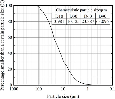
Figure 1. Particle size distribution of copper tailings.
2.2 Test equipment
The test device is composed of three parts, namely, hydraulic pulping part, grouting and dewatering part and data acquisition part, as shown in Figure 2 below.
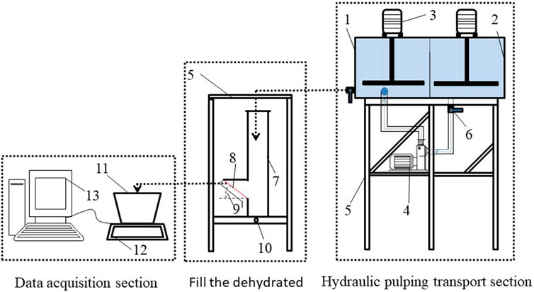
Figure 2. Test device (1-Tailings slurry supply tank; 2 - Reflow tank, it is used to collect the overflow part of the supply tank tailings slurry and stabilize the water level of the supply tank; 3 - Mixer, it used to prevent the deposit of tailings; 4 - Pump machine, it is to achieve the tailings slurry circulation from the reflow tank to the supply tank; 5-Bracket; 6 - Valve; 7-Acrylic square pipe; 8 - Geotextile; 9- Drainage boundary angle, α; 10 - Rotating support, it is used for adjustable angles; 11 - filtrate collection box; 12 - High precision electronic scale; 13 - Computer).
After the tailings slurry supply tank is full of liquid, the tailings slurry supply tank is returned to the reflow tank, so as to control the liquid level of the supply tank and realize the stability of the grouting flow supply. Besides, a mixer is arranged in two slots in the hydraulic pulping conveying part, the purpose is to prevent the tailings particles from settling in large quantities in the slurry supply tank, thereby providing a stable slurry concentration. Considering that the actual geotextile tubes can reach 70–100 cm after grouting, the design length of the acrylic square tube is 1m, the section size is designed to be 10*10 cm, and the section size of the geotextile is designed to be 10*14.5 cm considering the scale effect. When the acrylic square tube is placed vertically, the angle between the geotextile and the horizontal is 45°. And the angle can be adjusted to 30° and 60° respectively when it is rotated to the two sides by rotating the support.
2.3 Test scheme
2.3.1 Test purpose
With the increase of the grouting volume of ultra-fine tailings, the curvature of the lateral boundary of the geotextile tubes changes constantly. In order to better study the drainage performance of the lateral boundary of the geotextile tubes, three typical geotextile tilt angles of 30°, 45° and 60° were selected to simplify the arc of the lateral boundary of the geotextile tubes, analyze the formation and the dehydration process of the surface filter cake of the lateral boundary of the geotextile tubes, and study the hydraulic characteristics, tailings flow and particles deposition near the geotextile tubes. The development and evolution regularity of the filter cake structure of the surface geotextile on the lateral boundary of geotextile tubes was investigated, and the dewatering process law of the structure of geotextile -filter cake was revealed.
2.3.2 Test conditions
There are quite a few factors that affect the dewatering efficiency in the grouting stage of geotextile tubes, such as geotextile types, tailings slurry properties, tailings slurry pumping speed and so on. In this test, two main influencing factors, grouting flow rates (Qin) and tailings mass concentrations (w), were selected to study the formation of surface filter cake and dewatering performance of geotextile tubes during tailings slurry grouting and grouting, corresponding to two relevant evaluation indexes: maximum thickness of filter cake (h) and filtration velocity (vm,t). Then, the selection and origin of the parameters related to the test were described as follows: first, drainage boundary angle α is defined as the acute angle between geotextile and horizontal axis. Second when pulp mass concentration w was a constant value, the conversion relationship between dry tailings mass consumption and slurry grouting flow rates was as follows: Qin * t = Gs * Vs/w, where Qin was the grouting flow rates (In the physical model test, due to the limitations of the experimental device, the experimental device can only carry out low-flow related perfusion tests. Besides, the pump power was controlled by adjusting the current frequency of the power distribution box, and the slurry grouting flow rates reached the constant value predicted by the test), t was the grouting time, and Vs is the skeleton volume of tailings particles. Third, this experiment studied the effect of grouting low-mass concentrations pulp on the formation and dewatering performance of the surface filter cake of the geotextile tubes, aiming to provide relevant test data support for the follow-up study on the solution to the dewatering difficulty of the surface filter cake of the geotextile tubes, because relevant studies have shown that the concentration mass of the slurry directly affects the flocculation and coagulation effect of the chemical on the tailings. Then, for limited test conditions, the thickness of the filter cake on the surface of the geotextile was measured 3 times with a ruler and the average value was taken as the final thickness of the filter cake. Besides, during the grouting process, the filtrate discharged from the geotextile was collected by a collection box, which was placed on a high-precision electronic scale. The electronic scale connected to the computer through a serial port to realize real-time recording of the filtrate mass, and the recording interval was set to 1 s. When the time is t, the filtration velocity vm,t of pulp at time t can be obtained by subtracting the filtrate mass obtained at the next time interval from the filtrate mass obtained at this time. Its size can reflect the speed of dehydration in the grouting process, and the specific calculation is shown in the following equation: vm,t = (mt+1 - mt)/Δt, mt represents the filtrate mass obtained at time t; mt+1 represents the filtrate mass obtained at time t + 1, ∆t = 1s. Last, relevant tests conditions are designed in TABLE 1 below:
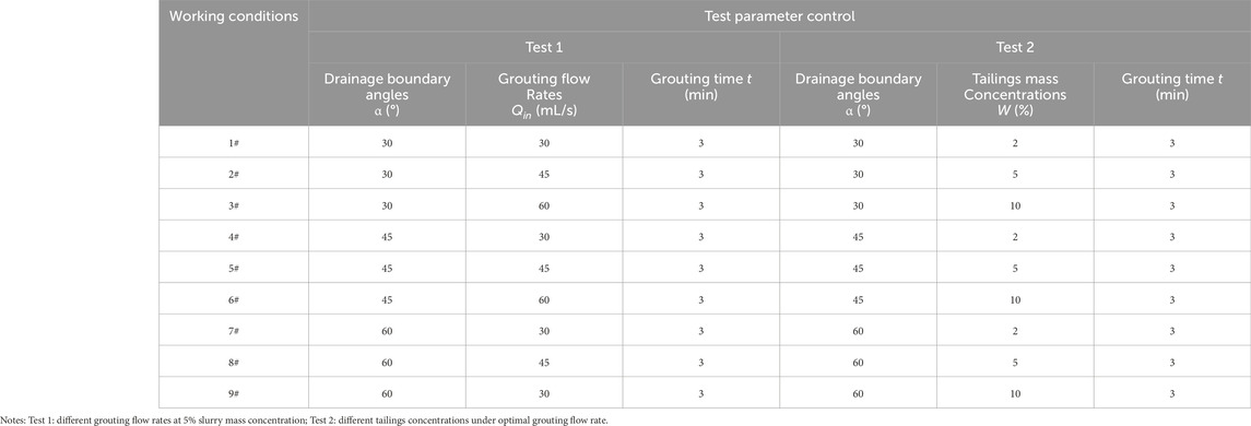
Table 1. Two tests conditions design.
2.3.3 Test procedure
First, it is necessary to assemble the equipment, make pipe joints waterproof good and clarify the function of each valve; Second, to check the waterproof and impervious performance of the test device through pure water, and determine the corresponding valve opening size of different grouting flow rates, so as to facilitate the selection of the required grouting flow rate when filling the grouting body.
Third, the ultra-fine tailings slurry with 5% mass concentration was configured, and then the geotextile was fixed with an inclination angle of 30°. The dehydration test of three different grouting flow rates of 30 mL/s, 45 mL/s and 60 mL/s is conducted successively from small to large. After the test of this angle is completed, other angles are replaced successively, and the above steps were repeated. During the test process, all data should be recorded at the same time to analyze the influence of the change of grouting flow rates on the test results.
Then, after analyzing the influence of grouting flow rates on the test results, the optimal grouting flow rate is selected, and the angle of fixed geotextile is 30°. Dehydration test is carried out at 2% mass concentration. After the completion of this angle, other angles were replaced for test.
Last, after the grouting test of 2% mass concentration under the optimal grouting flow rate, the slurry mass concentration is increased to 10%, and then the dehydration test under three angles is carried out successively. After the test, all the data are collected to analyze the influence of the slurry mass concentrations change on the test results.
2.4 Analysis of tests results
2.4.1 Influence of grouting flow rates on formation of filter cake
Figures 3A–I records the thickness of woven filter cake and the formation of surface filter cake under different working conditions respectively, and the specific analysis is as follows:
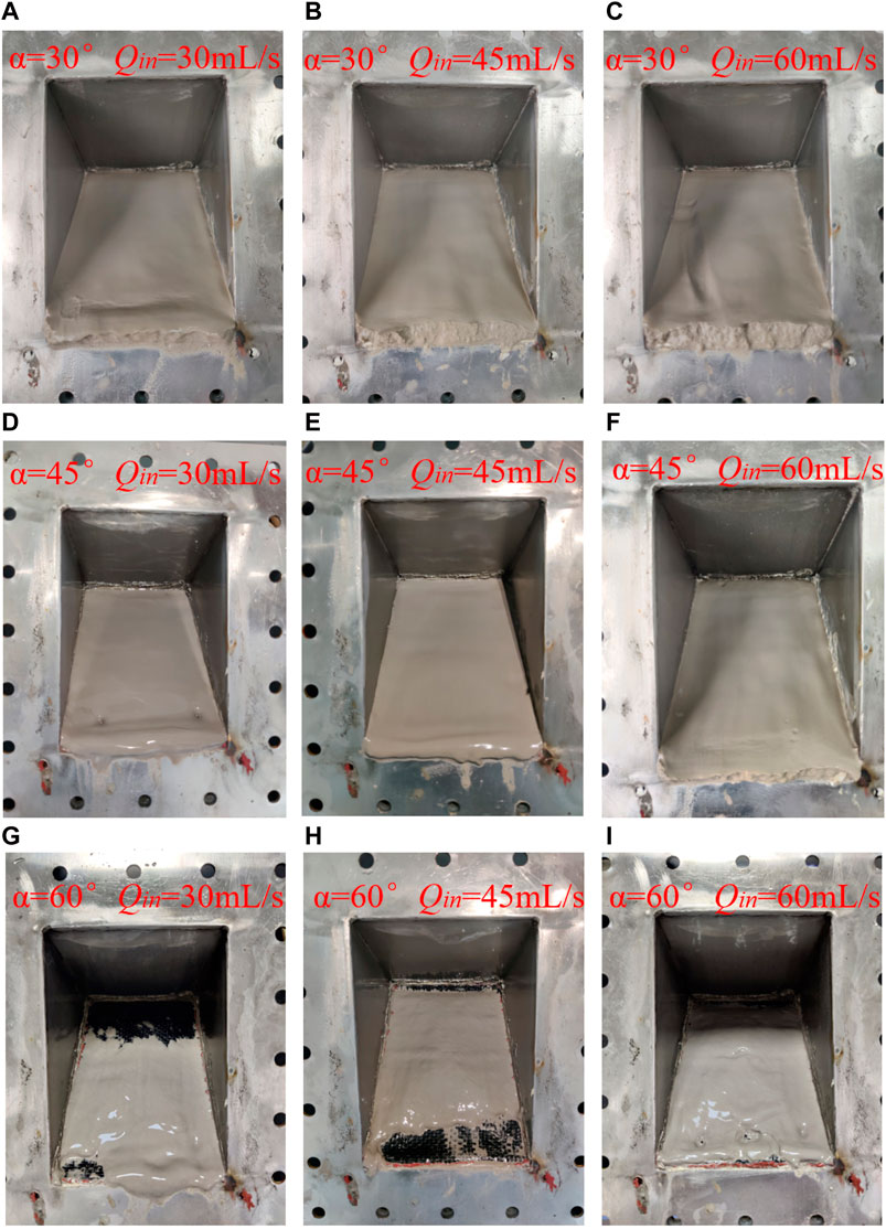
Figure 3. Final cake formation states under each working condition with a mass concentration of 5%, α is the lateral boundary angles and Qin is the grouting flow rates.
It is known from Figures 3A–C, when the slope angle of the drainage boundary is 30°, due to the relatively gentle angle, extremely serious silting occurs on the surface of the geotextile under the three grouting flow rates, forming a very uniform filter cake with dense surface and strong sand texture. When the grouting flow rates increased from 30 mL/s to 60 mL/s, the measured maximum thickness of cake was 9 mm, 13 mm and 14.5 mm, and the maximum thickness increased by 5.5 mm compared with the minimum thickness.
It is known from Figures 3D–F, when the slope angle of the drainage boundary is 45°, the filter cakes formed by the three grouting flow rates are uniformly and completely covered on the surface of the geotextile, and the thickness of the filter cakes formed by the three are slightly reduced from the upper end to the lower end of the geotextile. At this angle, the filter cake formed after being grouting with a flow rate of 30 mL/s was measured to have a maximum thickness of 6 mm. The filter cake had a strong sense of water quality on its surface, and there were two obvious circular holes near the end, indicating that the filter cake formed under this condition had a general density and was prone to collapse inside. When the grouting flow rate increases to 45 mL/s, the maximum thickness of the obtained filter cake is 8 mm, which is slightly increased compared with the previous situation, and the surface of the filter cake still has a slight sense of water quality, but the surface has no obvious depression. It is known from Figures 3G–I, when the grouting flow rate increases to 60 mL/s, it is found that the maximum thickness of the obtained filter cake increases to 9.5 mm, which is also increased compared with the working condition before, and the surface of the filter cake is dense and has obvious sand texture.
It is known from Figure 3G, when the drainage boundary angle is 60°, no complete filter cake structure is formed under the grouting flow rate of 30 mL/s, and a quarter of the area of the geotextile is completely exposed. The surface water quality of the filter cake in the rest of the geotextile is more than strong, with obvious traces of sliding and falling off. The measured maximum thickness is only 2 mm; When the grouting flow rate increased to 45 mL/s, the formed filter cake still could not cover the geotextile. However, different from the previous grouting flow rate, the filter cake at the upper end of the geotextile developed well, only a small area was exposed out of sight, but the filter cake near the lower end of the geotextile had fallen off, and the filter cake formed under this condition was gradually dense. However, the maximum thickness measured is only 2 mm; When the grouting flow rate increases to 60 mL/s, the filter cake almost completely covers the entire geotextile, but the sliding marks on the surface is obvious, and the depression near the lower end of the geotextile is also obvious, and the filter cake surface also has a sense of water quality, and the measured maximum thickness is 3 mm.
Through the analysis of the test results of three typical parts of the border of the geotextile tubes, it can be seen that the formation of the filter cake structure of the geotextile at the border of the geotextile tubes can be promoted at the angles of 30°–60° when the grouting flow rate is increased. This is because in the case of the same slurry concentration, the increase in the grouting flow rate makes the volume of the slurry pumped more, so the number of tailings particle entering the geotextile will be more; Then, the increase of slurry grouting flow will bring greater initial kinetic energy to tailings particle, which will accelerate the settlement of tailings particle, resulting in faster formation of filter cake, and the final formation of filter cake in the same time is thicker. Therefore, the increase of grouting flow rates will significantly promote the formation of filter cake for the lateral dewatering boundary of the entire geotextile tubes, and then perform a certain role in inhibiting the loss of tailings.
2.4.2 Influence of grouting flow rates on dehydration process
From Figure 4A it can be seen that when the drainage boundary angle is 30°, the great the grouting flow rate, the higher the filtration rate of slurry in the dehydration process. However, due to the serious silting of the surface layer of the geotextile under all grouting conditions at this angle, the overall filtration rate is very low, and the peak slurry filtration rate under the maximum filling flow rate is only 2.25 g/s. From Figure 4B it is seen that when the slope angle of the drainage boundary is 45°, the difference between the three curves corresponding to the slurry filtration rate in the 60 s before the test is small. However, the overall average filtration rate of the slurry under all grouting conditions is higher than that under the drainage boundary inclination of 30°, and the peak filtration rate of the slurry under the maximum grouting flow rate reaches 4.2 g/s. It is known from Figure 4C, when the drainage boundary angle is 60°, grouting flow rate has almost no difference to the average filtration rate of slurry during grouting, therefore, the change of grouting flow has no significant effect on the slurry filtration rate, but it is significantly higher than the slurry filtration rate corresponding to the drainage boundary of 30° and 45°. The peak value is close to 7 g/s, and the final filtration rate is stable at 5 g/s. It can be concluded that under the three different parts of the lateral boundary, the 60° dip angle drainage boundary has the strongest drainage capacity. Figures 3G–I shows that at a high angle of 60° drainage boundary, the filter cake formed at a low grouting flow rate is looser and incomplete, and the filter is controlled by the exposed geotextile and the locally formed filter cake. The filter cake formed under large grouting flow rate is more complete, and the dehydration process is controlled by the filter cake, so the permeability coefficient of the filter system formed under 30 mL/s grouting flow is higher than that under 60 mL/s grouting flow rate.
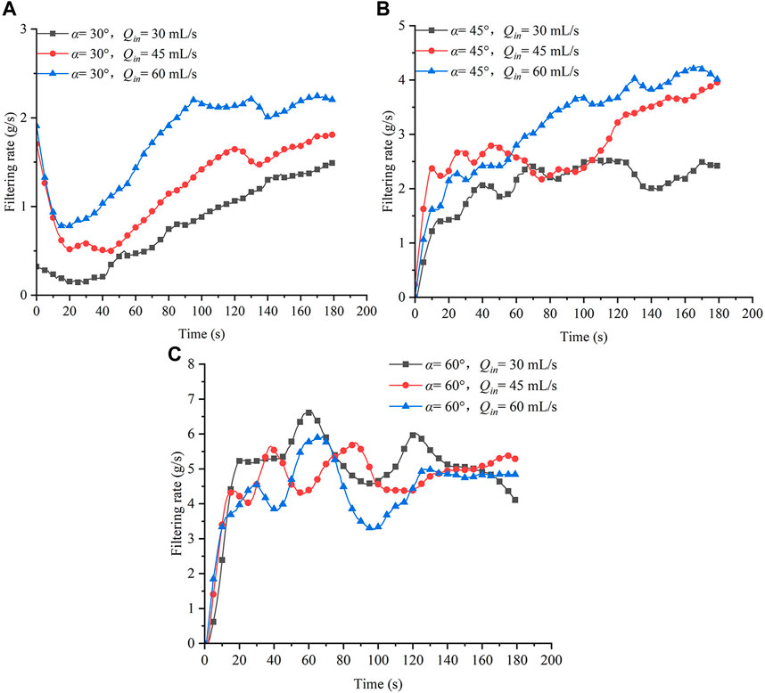
Figure 4. Filtration rate of slurry under different grouting flow rates and drainage boundary angles: (A) Filtration rate of slurry under different grouting flow rates at 30° drainage boundary; (B) Filtration rate of slurry under different grouting flow rates at 45° drainage boundary; (C) Filtration rate of slurry under different grouting flow rates at 60° drainage boundary.
2.4.3 Influence of slurry mass concentrations on filter cake formation
According to the analysis of the lateral boundary blockage caused by the change of grouting flow at 5% slurry concentration, it can be seen that the increase of grouting flow will aggravate the surface blockage, reduce the dehydration efficiency, and is not conducive to the progress of dehydration. Therefore, the optimal grouting flow rate is selected as 30 mL/s, and then the grouting dehydration test with 2% and 10% slurry mass concentrations at each drainage boundary angle is carried out.
The test results in Figures 5A–I show that theincrease of slurry mass concentrations has the same effect on the silting of the three lateral boundaries of the design condition of the test, and both promote the formation of filter cake. It is known from Figures 5A–C, when the concentrations of ultra-fine tailings slurry increase from 2% to 10%, the cake is most easily formed in the part, that is, when the slope of the drainage boundary is 30°, the maximum thickness of the filter cake obtained by measurement is 2.5 mm, 9 mm and 16 mm, and the difference between the maximum and minimum thickness of the filter cake is 13.5 mm; From Figures 5D–F it is seen, when the slope angle of the drainage boundary is 45°, the maximum thickness of the filter cake is 1.5 mm, 6 mm and 12.5 mm, and the maximum and minimum thickness of the filter cake also increase by 11 mm. It is known from Figures 5G–I, even in the part where the cake is least easy to form, that is, at the angle of the drainage boundary of 60°, no cake is formed on the surface of the geotextile at the lowest concentrations, and the maximum thickness of the cake finally formed at the maximum concentration is 8 mm. It can be seen from Figures 5A–G that with the increase of grouting concentrations under each drainage boundary, the generated filter cake structure becomes denser. At the concentration of 2%, the surface water quality of the filter cake is very strong, and the sliding traces are obvious. With the increase of slurry concentrations, the sense of water quality on the cake surface gradually decreases, and the sand texture becomes obvious. The main reason for the above phenomenon is: according to the stokes sedimentation law, the particle sedimentation speed is proportional to the square of the particle diameter. It can be seen from the particle size grading curve of tailings that the particle is big and small, when the tailings concentrations increase, the number of particles with larger particle size in the slurry increases, therefore, the big particle settle and accumulate rapidly, which makes the geotextile surface bridge form a thicker filter cake structure. In addition, in the process of slurry grouting, the fine particle moves with the water flow, resulting in a phenomenon of drilling, resulting in smaller pores and less water in the cake, so that the cake thickness becomes larger and the structure becomes denser.
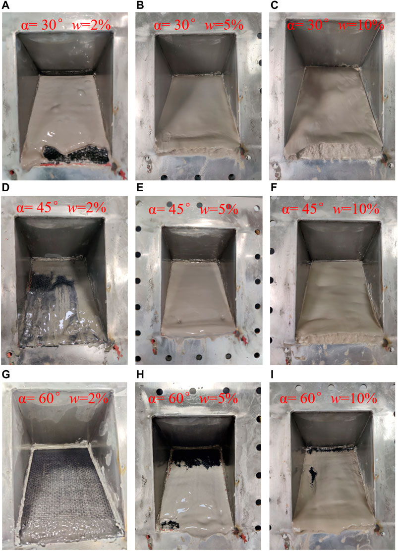
Figure 5. Final cake shapes at a grouting flow rate of 30 mL/s, α is the lateral boundary angles; w is the slurry mass concentrations.
2.4.4 Influence of slurry mass concentrations on dehydration process
It can be seen from Figure 6A that the average filtration rate of the whole slurry shows a decreasing trend with the increase of slurry mass concentrations. The peak filtration rate is 1.1 g/s at 10% concentration and 2 g/s at 2% concentration. Under this drainage boundary, it is observed that the dehydration rate at 10% concentration is significantly higher than that at 5% concentration 30 s before slurry grouting, but with the continuous grouting, the dehydration rate at 5% concentration is larger than that at 10% concentration. Because as the grouting process continues, under high concentration grouting conditions, the fine particle pumped into the slurry will carry the initial kinetic energy, a large number of particles enter the cake skeleton, which reduces the cake porosity and increases the specific resistance. It can be seen from Figure 6B that with the increase of slurry concentrations, the average dehydration rate of slurry decreases. At 2% concentration, the filtration rate of slurry remains stable at 4.75 g/s for a long time, while at 10% concentration, the average dehydration rate drops sharply to 1.25 g/s. Because the increase of the concentration promotes the formation of the filter cake, the specific resistance of the filter cake becomes larger. According to Figure 5G, Figure 6C, since no filter cake is generated on the surface layer of the geotextile at the concentration of 2%, the filtration is only controlled by the geotextile during the dehydration process, and the peak filtration rate reached 10.5 g/s. With the increase of the concentration, the filter cake also gradually formed at this angle, resulting in a sudden drop in the filtration rate. This shows that the specific resistance of filter cake is the main factor leading to the decrease of slurry filtration rate. The direct factor affecting the specific resistance of filter cake is the slurry concentration. According to the comparative analysis of Figures 6B, C, for the dehydration process of slurry with low concentrations (less than 10%), under the condition of a certain slurry concentration, different drainage boundary inclination angles have a great influence on the filtration rate of tailings slurry. However, when the tailings slurry concentrations reach 10% or more, the change of the inclination Angle of the drainage boundary has no significant effect on the tailings slurry filtration rate. Therefore, the influence of multiple factors on the filtration rate of low concentrations slurry in the process of grouting and grouting may be the result of coupling.
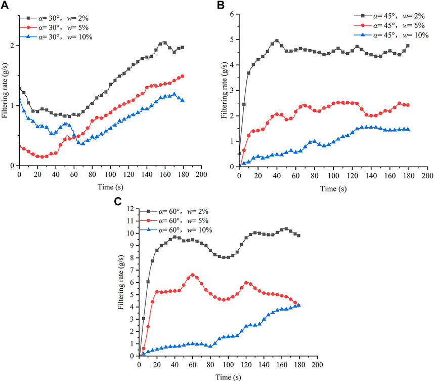
Figure 6. Filtration rate under different slurry concentrations and drainage boundary angles: (A) Filtration rate of slurry under different slurry concentrations at 30° drainage boundary; (B) Filtration rate of slurry under different slurry concentrations at 45° drainage boundary; (C) Filtration rate of slurry under different slurry concentrations at 60° drainage boundary.
3 Numerical simulation
3.1 Numerical model establishment
3.1.1 Device model
In numerical simulation, the physical model of the lateral boundary is simplified. The SpeaceClaim built into ANSYS is used for model design and fluid region volume extraction. The length of the square tube of the numerical model is 100 mm for research, the effective section size is 25 mm × 25 mm, the width of the geotextile is reduced to 25 mm, and the other sizes are also reduced. Lateral drainage boundary point of the selection of the same as the physical model test, to 30°, 45° and 60° three instead of geotextile tubes lateral tilt boundary three typical parts. After the model is established, MESH plate in commercial software Fluent is used for a grid division, as shown in Figure 7.
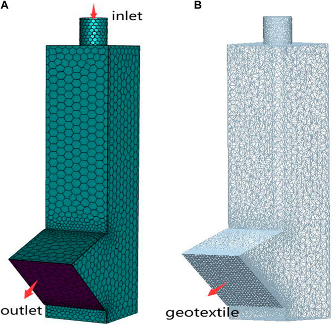
Figure 7. Numerical model (taking the drainage boundary at 45° as an example. (A) Fluent grid model; (B) EDEM grid model).
3.1.2 Material model
3.1.2.1 Particle model
According to the particle size grading analysis and test of copper tailings, its average particle size is only 19.85 um and D90 is only 63 um, with extremely fine particle. However, in EDEM, too small particle diameter will directly lead to a precipitous decline in computational efficiency, and also easily lead to non-convergence of numerical simulation results. Therefore, it is difficult to model and calculate according to the actual particle size of ultra-fine tailings, and it is necessary to properly enlarge the particle. Version 2.3 of the UNINSIM (Common Simulation) compilation provides particle magnification to improve computational efficiency while also making the results easier to converge. UNINSIM also validates this functionality. In this study, similar processing is carried out based on the particle size information of ultra-fine tailings, and the particle is enlarged with the amplification factor of 10.
The influence of particle shapes on numerical simulation results is also considered. According to the SEM scanning results of ultra-fine tailings, the shapes of tailings mostly show three shapes similar to circles, rectangles and triangles. Therefore, in EDEM, three kinds of tailings particle, such as spherical, rectangular and triangular, are constructed on the basis of spherical particle, as shown in Figure 8A. The proportion of the three types of particle is 1/3 each.
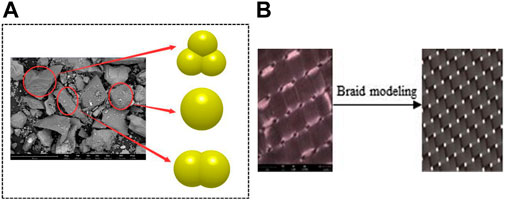
Figure 8. Material model: (A) Tailings particle model; (B) Equivalent model of geotextile.
3.1.2.2 Geotextile model
As the particle is amplified, the geotextile aperture is appropriately amplified to ensure that the particle is effectively intercepted and allowed to partially pass through the geotextile. The results of electron microscopy show that geotextile is made of crisscross fibers, and there may be gaps in the crisscross nodes or surfaces. In order to facilitate modeling, the pores of geotextile are replaced by evenly distributed pores, which are equivalent to the braided sieve structure, and the holes are uniformly taken as 0.25 mm, as shown in Figure 8B.
3.2 Numerical simulation conditions
The variables studied in the physical model test are two aspects: grouting flow rates and slurry concentrations, and three gradient values are taken for each variable. Then, the variables studied in numerical simulation are inlet speeds v and particle mass flow rates Qm respectively corresponding to grouting flow rates and slurry concentrations in the physical model. According to the physical model test, when the slurry grouting time is 3 min and the grouting flow rates are 30 mL/s and 60 mL/s, the liquid level height of tailings slurry in acrylic square tube reaches 50 cm and 90 cm respectively, so the tailings solid mass ms = A*h*w, and the particle mass flow rate Qm = ms/t, A is acrylic square tube section area in physical model test, h is the liquid level height of tailings slurry grouting 3 min in the acrylic square tube, w is tailings slurry mass concentration. Considering that it would be too costly to compute all the cases in the numerical simulation, only two representative values are taken for each variable. Through the pre-simulation, it is found that if the particle filtration rates are designed according to the actual slurry concentrations, the number of particles will be as high as one million, and the calculation speed will be seriously reduced. In order to ensure the effectiveness of the final simulation results, the total number of particles should be controlled within 200,000–300,000. So the actual tailings slurry concentration is converted, the number of particle is appropriately reduced, the approved inlet speed is converted according to 60 mL/s and 30 mL/s, and the slurry concentration is converted according to 5% and 10%. In order to make the numerical simulation achieve a certain effect and save the calculation cost, the calculation time step of FLUENT is 5 × 10⁻⁴ s and EDEM is 1 × 10⁻⁶ s after several pre-simulations. The specific numerical simulation conditions are shown in Table 2.
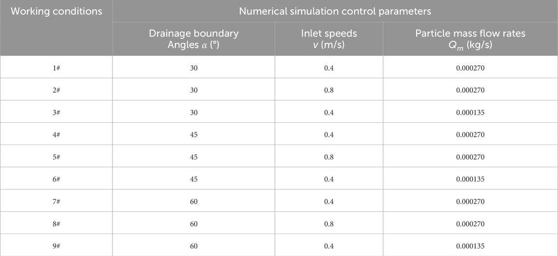
Table 2. Numerical simulation conditions.
3.3 Analysis of simulation results
3.3.1 Influence of inlet speeds on the formation of surface results
Grouting tailings slurry is simulated based on three typical lateral drainage boundaries, and the tailings slurry is injected at 0.4 m/s and 0.8 m/s respectively under the condition of keeping the particle concentration constant. With the continuous development of the flow field, the water flow will drag the tailings particle to toward the exit direction, and the tailings particle moved to the surface of the geotextile. After the test, it can be seen from Figures 9A1–B2, that with the increase of inlet speeds, the thickness of the final formed filter cake at 30° and 45° drainage boundary only has a slight increase, it is known from Figures 9C1, C2 that while the thickness at 60° drainage boundary has no increase, because the number of particle injected under each working condition is the same, so there is no obvious difference in the overall thickness of the filter cake finally formed under each drainage boundary angle. In fact, the change of inlet speed will have a certain impact on the internal structure of the filter cake formed, so there are differences in the coverage of the geotextile surface filter cake. Figures 10A–C, 1,2 reflects the spatial volume fraction of the particle at the bottom of the filter cake structure finally formed under the three typical lateral boundary angles of the geotextile tubes, and also reflects the distribution of the filter cake on the surface of the geotextile. It is known from Figures 10A1, B1, C1, when the slurry inlet speed is 0.4 m/s, the filter cake distribution of the surface layer of geotextile is incomplete at all angles, and the incomplete phenomenon is very significant at the top of the geotextile. Especially, at the lateral boundary angle of 60°, in addition to the top of the geotextile, the left and right ends also have obvious defects. It is known from Figures 10A2, B2, C2, when the inlet speed is 0.8 m/s, the final cake distribution at each lateral boundary angle is significantly changed and complete than that at the inlet speed of 0.4 m/s. Besides, with the increase of the inlet speeds, the volume fraction of the particle at the bottom of the filter cake formed at each lateral boundary inclination Angle is also larger. However, the larger the volume fraction of the particle phase, the smaller the space occupied by the fluid phase, the fewer pores in the cake, and the denser the cake structure. The reason is that if the larger the slurry inlet speed, the fluid will form a more uniform flow pattern in the geotextile surface layer, which helps the particle to form a wider distribution in the geotextile surface layer, resulting in the final formation of a filter cake completely covered in the geotextile surface.
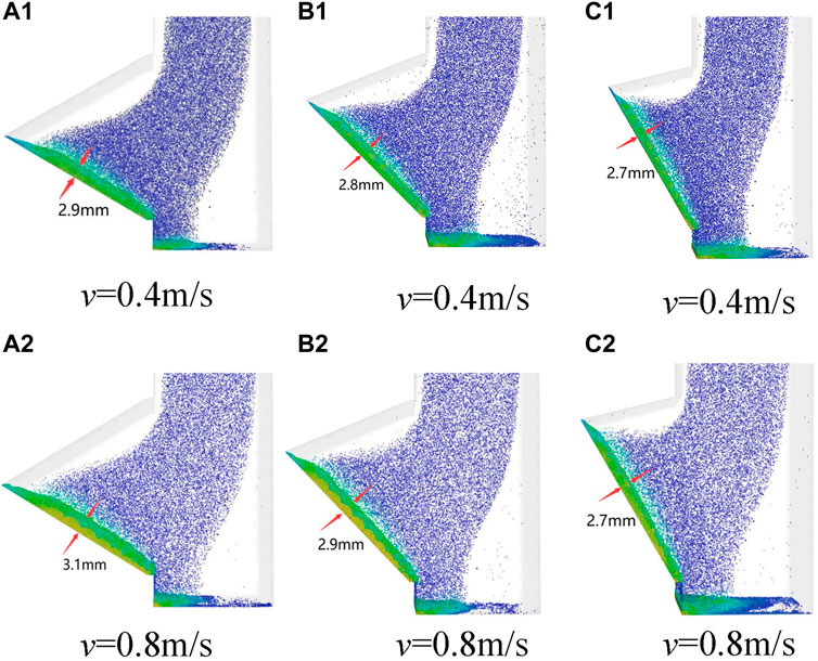
Figure 9. Thickness of cake accumulation on geotextile surface under different lateral boundary angles and different inlet speeds: (A) Thickness of cake accumulation on geotextile surface under different inlet speeds at 30° drainage boundary; (B) Thickness of cake accumulation on geotextile surface under different inlet speeds at 45° drainage boundary; (C) Thickness of cake accumulation on geotextile surface under different inlet speeds at 60° drainage boundary.
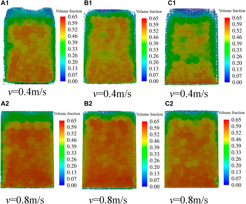
Figure 10. The proportion of the volume fraction of the particle at the bottom of the filter cake under different inlet speeds and different lateral boundary angles: (A) The proportion of the volume fraction of the particle at the bottom of the filter cake under different inlet speeds at 30° drainage boundary; (B) The proportion of the volume fraction of the particle at the bottom of the filter cake under different inlet speeds at 45° drainage boundary; (C) The proportion of the volume fraction of the particle at the bottom of the filter cake under different inlet speeds at 60° drainage boundary.
3.3.2 Influence of particle concentrations on the formation of surface cake
When the inlet speed of the slurry is 0.4 m/s, the particle is injected at the particle mass flow rates of 0.000135 kg/s and 0.000227 kg/s. After the grouting of the simulated ultra-fine tailings slurry, there are great differences in the formation of filter cake in three typical lateral boundary geotextiles under two working conditions. Firstly, there is a significant difference in thickness. It can be seen from Figures 11A1–C2 that with the increase of particle concentrations, the thickness of filter cake formed on the surface layer of the geotextile under each drainage boundary inclination angle increases significantly. Then, from Figures 12 A1, A2, it can be seen from the distribution of the filter cake and the spatial volume fraction of the particle, that at the lateral boundary with an inclination angle of 30°, the top of the final generated filter cake is significantly incomplete at low particle concentration, and the spatial volume fraction of the filter cake particle is also lower, and the particle is mainly accumulated at the bottom of the geotextile. With the increase of the tailings slurry concentrations, the cake accumulation in the whole cake layer is relatively more uniform, and the particle density also increases significantly from the perspective of the whole cake coverage. It is known from Figures 12 B1–C2, the same pattern is also observed with the change of particle concentrations at 45° and 60° at the lateral boundary. Under the condition that the tailings slurry inlet speed is constant, the formation of filter cake on the surface of the geotextile at the lateral boundary of the geotextile can be significantly promoted by increasing the particle concentrations. If the particle concentrations are higher, the number of tailings particles increases, and these particle is more likely to form thicker filter cake on the geotextile surface during the grouting process. Besides, with the increase of particle concentrations, the content of fine particle per unit volume also increases, and more fine particle is dragged into the generated filter cake by water flow to grout the pores therein, making the final cake structure denser.
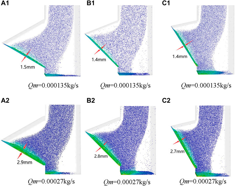
Figure 11. Thickness of cake accumulation on geotextile surface under different lateral boundary angles and different particle concentrations: (A) Thickness of cake accumulation on geotextile surface under different particle concentrations at 30° drainage boundary; (B) Thickness of cake accumulation on geotextile surface under different particle concentrations at 45° drainage boundary; (C) Thickness of cake accumulation on geotextile surface under different particle concentrations at 60° drainage boundary.
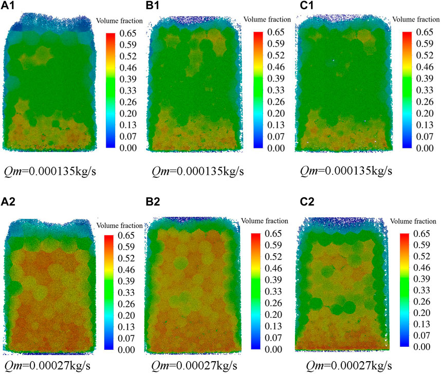
Figure 12. The proportion of the volume fraction of the particle at the bottom of the filter cake under different particle concentrations and different lateral boundary angles: (A) The proportion of the volume fraction of the particle at the bottom of the filter cake under different particle concentrations speeds at 30° drainage boundary; (B) The proportion of the volume fraction of the particle at the bottom of the filter cake under different particle concentrations at 45° drainage boundary; (C) The proportion of the volume fraction of the particle at the bottom of the filter cake under different particle concentrations at 60° drainage boundary.
4 Conclusion
In order to analyze the surface filter cake formation and the dehydration performance of the inner lateral boundary of the geotextile tubes in the process of grouting and grouting the geotextile tubes with ultra-fine tailings, this article adopts the method of combining physical model test and numerical simulation, the following conclusions can be obtained:
(1) The physical model test results show that increasing tailings slurry grouting flow will promote the formation of filter cake structure on the surface of geotextile, but has no significant effect on the dewatering performance of tailings slurry at different drainage boundaries.
(2) The physical model test results show that: the larger the tailings slurry mass concentrations, the thickness of the filter cake formed on the surface of the geotextile at the lateral boundary of the geotextile tubes will increase significantly, and the structural compactness will also increase significantly, which will lead to a significant decrease in the dehydration speed and efficiency during the grouting process.
(3) The numerical simulation results show that: the higher the inlet speed, the more complete the surface cake is formed, and the compactness of the cake structure is improved to some extent; The larger the particle concentrations are, the thicker the filter cake is formed on the surface of the lateral boundary geotextile, and the density of the filter cake structure is significantly improved.
Data availability statement
The raw data supporting the conclusions of this article will be made available by the authors, without undue reservation.
Author contributions
MS: Writing–original draft, Writing–review and editing, Conceptualization, Supervision. QZ: Writing–original draft, Writing–review and editing. FH: Formal Analysis, Validation, Writing–original draft. CZ: Data curation, Software, Writing–original draft. YG: Resources, Visualization, Writing–original draft. XL: Writing–review and editing, Methodology, Project administration.
Funding
The author(s) declare that financial support was received for the research, authorship, and/or publication of this article. This study was supported by the National Natural Science Foundation of China (52069013 and 52169027), which is gratefully acknowledged.
Conflict of interest
The authors declare that the research was conducted in the absence of any commercial or financial relationships that could be construed as a potential conflict of interest.
Publisher’s note
All claims expressed in this article are solely those of the authors and do not necessarily represent those of their affiliated organizations, or those of the publisher, the editors and the reviewers. Any product that may be evaluated in this article, or claim that may be made by its manufacturer, is not guaranteed or endorsed by the publisher.
References
Assinder, P., Breytenbach, M., Wiemers, J., and Hortkorn, F. (2016) “Utilizing geotextile tubes to extend the life of a Tailings Storage Facility,” in Proceedings of the first southern african geotechnical conference, 373–379. doi:10.1201/B21335-66
Chen, K., Zhu, J., Qian, F., Cao, B., Lu, J., and Han, Y. (2023). CFD–DEM simulation of particle deposition characteristics of pleated air filter media based on porous media model. Particuology 72, 37–48. doi:10.1016/j.partic.2022.02.003
Chunhe, Y., Chao, Z., Quanming, L., Yuzhen, Y., Changkun, M., and Zhijie, D. (2021). Disaster mechanism and prevention methods of large-scale high tailings dam. Rock Soil Mech. 42, 1–17. doi:10.16285/j.rsm.2020.1653
Guangwei, Z., Lijuan, T., and Zeli, L. (2017). Discussion on disposal and utilization of ultra-fine tailings. Met. Mine., 171–177. doi:10.ssss/j.issn.1001-1250.2017.2.030
Guangxiang, M., Shuai, L., Hongyan, L., Liling, H., Tao, M., Huadong, C., et al. (2021). Geotextile tubes technology for dewatering and volume reduction of sediments polluted by heavy metals and its engineering case. Chin. J. Environ. Eng. 15, 3773–3780. doi:10.12030/j.cjee.202101135
Guangzhi, L. (2013). Key Mechanics issues and construction technologies for the rapid raise of high tailings dam by using the upstream method. Chongqing (China): Chongqing University.
Haimin, W., Zhenyu, T., Yiming, S., Daihui, M., Yi, P., and Wenlong, M. (2021). Experimental study on the dewatering performance of geotextile tubes filled with silt-sand slurry using hanging bag tests. J. Tianjin Univ. (Sci. Technol). 54, 487–496. doi:10.11784/tdxbz202004075
Huang, C. C., Jatta, M., and Chuang, C. C. (2012). Dewatering of reservoir sediment slurry using woven geotextiles. Part II: analytical results. Geosynth. In. 19, 93–105. doi:10.1680/gein.2012.19.2.93
Huang, C.-C., and Luo, S. (2007). Dewatering of reservoir sediment slurry using woven geotextiles. Part I: experimental results. Geosynth. In. 14, 253–263. doi:10.1680/GEIN.2007.14.5.253
Huang, F., Yan, J., Fan, X., Yao, C., Huang, J., Chen, W., et al. (2022). Uncertainty pattern in landslide susceptibility prediction modelling: effects of different landslide boundaries and spatial shape expressions. Geosci. Front. 13, 68–83. doi:10.1016/j.gsf.2021.101317
Huang, F., Ye, Z., Jiang, S.-H., Huang, J., Chang, Z., and Chen, J. (2021). Uncertainty study of landslide susceptibility prediction considering the different attribute interval numbers of environmental factors and different data-based models. Catena 202, 105250. doi:10.1016/j.catena.2021.105250
Jiang, S.-H., and Huang, J. (2018). Modeling of non-stationary random field of undrained shear strength of soil for slope reliability analysis. Soils Found. 58, 185–198. doi:10.1016/j.sandf.2017.11.006
Jiang, S.-H., and Huang, S.-H. (2016). Efficient slope reliability analysis at low-probability levels in spatially variable soils. Comput. Geotech. 75, 18–27. doi:10.1016/j.compgeo.2016.01.016
Kim, H. J., and Dinoy, P. R. (2021). Two-dimensional consolidation analysis of geotextile tubes filled with fine-grained material. Geotext. Geomembranes 49, 1149–1164. doi:10.1016/j.geotexmem.2021.03.009
Kim, H. J., Park, T. W., Dinoy, P. R., Kim, H. S., and Kim, H. J. (2018). Design and consolidation analysis of geotextile tubes for the Saemangeum project in Korea. Geosynth. Int. 25, 507–524. doi:10.1680/jgein.18.00015
Moo-Young, H. K., Gaffney, D. A., and Mo, X. (2002). Testing procedures to assess the viability of dewatering with geotextile tubes. Geotext. Geomembranes 20, 289–303. doi:10.1016/s0266-1144(02)00028-6
Ratnayesuraj, C. R., and Bhatia, S. K. (2018). Testing and analytical modeling of two-dimensional geotextile tube dewatering process. Geosynth. Int. 25, 132–149. doi:10.1680/jgein.17.00038
Shui-Hua, J., Jinsong, H., Chi, Y., and Jianhua, Y. (2017). Quantitative risk assessment of slope failure in 2-D spatially variable soils by limit equilibrium method. Appl. Math. Model. 47, 710–725. doi:10.1016/j.apm.2017.03.048
Stoltz, G., Delmas, P., and Barral, C. (2019). Comparison of the behaviour of various geotextiles used in the filtration of clayey sludge: an experimental study. Geotext. Geomembranes 47, 230–242. doi:10.1016/j.geotexmem.2018.12.008
Ward, N. D., and Weggel, J. R. (2012). A model for filter cake formation on geotextiles: theory. Geotext. Geomembranes 31, 51–61. doi:10.1016/j.geotexmem.2011.10.002
Weggel, J. R., and Dortch, J. (2012). A model for filter cake formation on geotextiles: experiments. Geotext. Geomembranes 31, 62–68. doi:10.1016/j.geotexmem.2011.10.003
Wu, S., Chen, Y., Zhang, P., Dong, S., Qi, Y., and Min, F. (2024). Pore characteristics of cake by filtration based on LBM-DEM-DLVO coupling method. Powder Technol. 431, 119109. doi:10.1016/j.powtec.2023.119109
Xinxin, L., Mingqiang, S., Guangxu, X., and Yabing, H. (2020). Field test study on damming of tailings ponds for emergency flood control. Yellow River 42, 136–141. doi:10.3969/j.issn.1000-1379.2020.07.030
Xinyang, X., and Qian, L. (2001). Study on the compressibility and specific resistance of filter cake. Met. Mine. 12, 34–38.
Yabing, H., Xuan, C., and Yongbo, Q. (2019). Industrial test of damming using different kinds of geofabriform filled with graded tailings. Nonferrous Met. Min. Sect. 71, 41–46. doi:10.3969/j.issn.1671-4172.2019.04.009
Yujuan, L., Qiuyue, W., Xuemei, S., Zhiwei, Z., Yimin, Z., and Yuexiang, G. (2023). Pollution characteristics and source identification of heavy metals in farmland soils around a tailing pond in Zhejiang Province. J. Environ. Eng. Technol. 13, 1464–1475. doi:10.12153/j.issn.1674-991X.20221193
Zhong-min, L. (2009). Application of geosynthetics to reservoir construction in tidal estuary area. Adv. Sci. Technol. Water Resour. 29, 39–41. doi:10.3880/j.issn.1006-7647.2009.06.010
Keywords: lateral boundary of geotextile tubes, ultra-fine tailings, physical model test, filter cake formation, numerical simulation
Citation: Sheng M, Zhu Q, Huang F, Zou C, Gao Y and Liu X (2024) Study on the formation and dewatering process of the surface filter cake of geotextile on the lateral boundary of geotextile tubes under constant flow grouting. Front. Earth Sci. 12:1427659. doi: 10.3389/feart.2024.1427659
Received: 04 May 2024; Accepted: 28 June 2024;
Published: 31 July 2024.
Edited by:
Xianwei Zhang, Chinese Academy of Sciences (CAS), ChinaReviewed by:
Jifei Cui, University of Shanghai for Science and Technology, ChinaYajun Li, China University of Geosciences, China
Ruping Luo, East China Jiaotong University, China
Copyright © 2024 Sheng, Zhu, Huang, Zou, Gao and Liu. This is an open-access article distributed under the terms of the Creative Commons Attribution License (CC BY). The use, distribution or reproduction in other forums is permitted, provided the original author(s) and the copyright owner(s) are credited and that the original publication in this journal is cited, in accordance with accepted academic practice. No use, distribution or reproduction is permitted which does not comply with these terms.
*Correspondence: Xinxin Liu, huashuiliuxin@126.com