 Peng Bai
 Zhiyong Li1
- 1Shaanxi Huadian Yuheng Coal Power Co., Ltd., Xiaojihan Coal Mine, Yulin, Shaanxi, China
- 2Xi’an University of Science and Technology, Xi’an, Shaanxi, China
Introduction: Nearly vertical coal seams present a significant challenge for the coal mining industry due to their difficult accessibility. However, these seams account for a substantial proportion of the world’s coal reserves. Therefore, it is vital to conduct research on disaster control techniques for safe mining of these seams.
Method: The research team used experimental research, theoretical analysis, and numerical calculation methods to investigate the creep characteristics and failure mechanisms of layered sandstone roadway in nearly vertical coal seam.
Results and discussion: These findings revealed that the maximum moment and concentrated stress of the sandstone located on the side of the roadway roof was positioned in the middle of the nearly vertical structure, making it more susceptible to transverse shear failure. On the other hand, the nearly vertical structure on the floor side was prone to shear slip failure initiated from the bottom of the structure. This led to the asymmetric instability of the roadway. The practical implications of this research are significant for the safe mining of nearly vertical coal seams. The results could help inform the development of disaster control techniques.
1 Introduction
Creep behavior generally refers to the time-dependent behavior of material deformation rate, delayed fracture and long-term strength reduction behavior (Rui et al., 2021; Xingping et al., 2024). Bhasin (Bhasin and Grimstad, 1996) found that when subjected to high in-situ stress, the weak surrounding rock containing clay and salt will also produce creep. In addition, due to the particularity of layered sandstone structure, its creep characteristics and failure mechanism are special, so it is necessary to carry out systematic research.
Kazuhiko Miura (Miura et al., 2003) proposed a prediction model for creep failure of hard rock based on micromechanics. Hakan Ozsen (Ozsen et al., 2014) established a mathematical model to express the multi-parameter relationship of stress and strain. M. H. Leite (Leite et al., 1993) established a rock creep model based on the power law of transient creep, and the short-term creep parameters of rock were determined. Jan S. Cornet (Cornet et al., 2018) quantified the long-term creep under the condition of in situ salt cavity closure, incompressible carol viscosity model was used to study the regularity of dislocation creep and stress solution. By means of a combination of energy dispersive X-ray spectroscopy and micromechanical model, the influence of temperature on ultra-micro creep properties of shale was investigated (Sharma et al., 2018). Based on morphological evolution simulation, engineering geological simulation and numerical simulation, a multi-model analysis method was established by F. Bozzano (Bozzano et al., 2016) to study the creep behavior and failure mechanism of slope rock. The creep tests of argillaceous rock under various stress conditions showed that when the cracks of argillaceous rock were unstable, the overall mechanical properties of argillaceous rock deteriorated rapidly, and the creep of clay particles caused the viscoelastic strain of argillaceous rock (Fabre and Pellet, 2006). The difference of creep mechanism between coarse-grained dolomite and fine-grained dolomite was revealed by triaxial compression experiments of dolomite (Wang et al., 2015). Bin G. (Bing et al., 2024) introduces a novel implicit continuous to discontinuous method to investigate the cross-scale failure process of discontinuous rock masses, including fine fracture creation, propagation, and rigid block contact. This method enables an intact rock to split and crush, with the local deformation/movement propagating rapidly throughout the whole system. The observation of microstructure showed that grain boundary migration and recrystallization played an important role in dislocation creep, and the strength of anorthosite decreases with the increase of water content (Yanpeng et al., 2024). Under the background of microstructure analysis acoustic emission source location and macroscopic creep law, the mechanism of pore water in sandstone influenced by stress corrosion cracking was studied (Baud et al., 2009). The deep creep mechanism of slope rock mass was analyzed by means of simulation method. It was also pointed out that the main factor controlling the deep creep mechanism was the propagation of subcritical crack (Brückl and Parotidis, 2005). To understand the effect of transverse isotropy on the deformability and tensile strength of shales subjected to dynamic loading, researchers carried out a group of impact Brazilian tests on shale specimens via a split Hopkinson pressure bar (SHPB) testing system. High-speed digital image correlation technology was applied to monitor the fracture process. The experimental results demonstrate that the failure strength has considerable anisotropy as the bedding angle of the embedded layers changes (Xianhui et al., 2024). The indentation experiments on quartz crystals were carried out by Jean Pierre Gratier (Gratier et al., 2009), and the indentation creep law under the middle and upper crust was summarized. The rheological behaviors of quartz and feldspar rocks were compared and analyzed by thermodynamic model (Závada et al., 2007). Kiyokazu Oohashi (Oohashi et al., 2012) studied the influence of graphite content in fault rocks on the formation and evolution of fault creep rocks. Doug Stead (Stead and Wolter, 2015) emphasized on the importance of structural geology in slope stability assessment, the failure mechanism of slope controlled by structure was reviewed.
Experimental research is a kind of effective method to obtain rock mechanics behavior. Especially in recent years, along with the improvement equipment, it speed up the process of rock creep research, making outstanding contributions to the study of the creep failure characteristics and the formulation of the solution plan. Geraldine Fabre (Pellet and Fabre, 2007) carried out static, quasi-static and cyclic creep tests on sedimentary rocks. The results showed that clay particles had a significant effect on the creep behavior. S. Rahimi (Rahimi and Hosseini, 2014) performed triaxial creep tests on thick-walled hollow columnar rock salt to study the effects of confining pressure and deviating stress on the creep behavior of rock salt. Results showed that the strain rate increased with the increase of deviating stress and confining pressure. D. Grgic (Grgic and Amitrano, 2009) studied the influence of water saturation on rock creep by multi-step uniaxial creep experiment of polycrystalline porous rock, and the important role of micro-fracture in the creep process was illustrated. S. Nadimi (Nadimi et al., 2011) used the creep experiment and field measurement data to estimate the dynamic constitutive model of creep parameters of rock. Under high temperature, axial differential pressure stress and low confining pressure, the creep strain was enhanced (Herrmann et al., 2020). In addition, the authors have accomplished related researches on rock and same type of material. The results have implications for this research (Lianpeng et al., 2021; Huicong et al., 2023; Xu et al., 2023; Yongyi et al., 2023; Pan et al., 2024).
Through the review of researches on the failure mechanism of rock mass creep characteristics, scholars have innovative ideas in theoretical research, experimental design and numerical simulation. Many beneficial research results have been achieved. However, most studies focus on rock masses without large internal primary structures. It can be found through on-site geological survey that the study area contains nearly vertical coal seam, and surrounding rock of sedimentary layered structure determines the uniqueness of the study, which requires systematic research on creep characteristics and failure mechanism of rock under special geological conditions.
2 Creep characteristics of layered sandstone samples
The creep test proposed in this study, which is conducted under uniaxial static load, adopts the ISRM method and ASTM criterion for rock creep under constant stress. The experiment mainly employs the rock rheological testing system. Additional auxiliary equipment, including strain gauges, a digital SWAES multi-channel acoustic emission device, and a Sony digital camera, were also utilized. The axial and radial strains were measured using strain gauges and the DD1 cantilever strain sensor, developed by the HBM Company.
Compressive stresses, equivalent to 30%, 40%, 50%, 60%, 70%, 75%, 80%, and 85% of the samples’ uniaxial compressive strength, were applied to the specimens, respectively. The stress control method was used for loading, with a loading rate of 0.01 kN/s. During the initial stage of the creep experiment, experimental parameters were read and recorded at intervals of 1.0, 5.0, and 10.0 min. The time interval was then extended to 0.5–1.0 h in the middle of the experiment. At the end of the experiment, when the rock sample was close to failure, the reading intervals for parameters were changed to be 10.0, 5.0, and 1.0 min.
Figures 1A–C show the time evolution of stress and strain for samples C1, C2, and C3. These samples underwent both the first and second stages under static load, and finally reached a stress equilibrium state in the second stage, without any overall or local damage. A small amount of debris was visible on the upper and lower surfaces of samples C2 and C3, caused by the large stiffness of the press bearing plate and press shaft, although this did not impact experimental results. It is noteworthy that static loading on samples C2 and C3 exceeded the CI threshold which could have caused new cracks on the samples, but it did not.
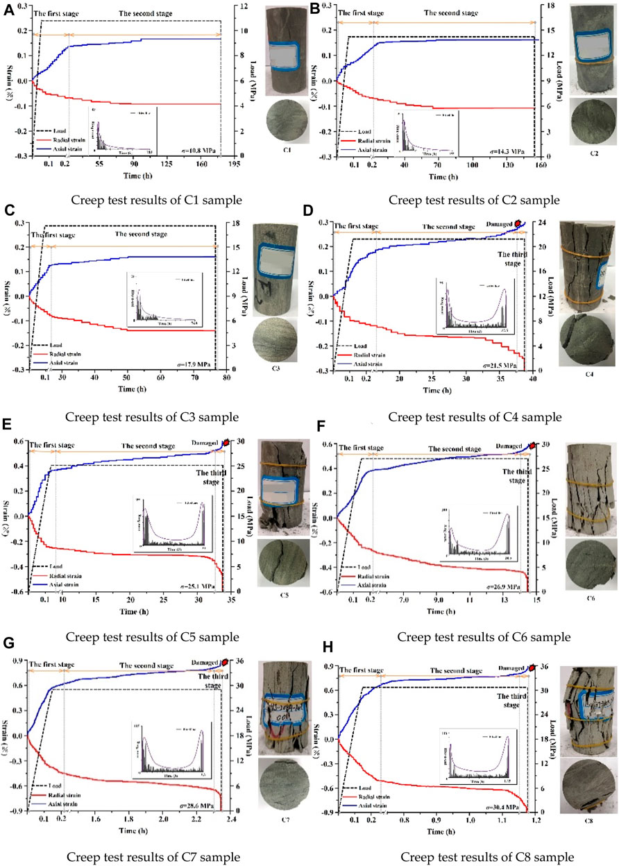
Figure 1. Creep test curve of rock samples. (A) Creep test results of C1 sample (B) Creep test results of C2 sample (C) Creep test results of C3 sample (D) Creep test results of C4 sample (E) Creep test results of C5 sample (F) Creep test results of C6 sample (G) Creep test results of C7 sample (H) Creep test results of C8 sample.
Figures 1D through H demonstrate the stress-strain evolution and failure modes for five rock samples (C4 to C8). The creep time decreases as the applied stress increases while the final creep and strain rate during the first stage increase proportionally to the applied stress as shown in Figure 2. The failure mode of the specimens is primarily shear failure occurring along the structural plane as well as in the normal direction to the structure through transverse shear failure. When under static load, the stress state of the vertical structural plane can be simplified as a plate structure with fixed ends. Under the influence of the horizontal component force, transverse tensile and shear failure occurs in the middle part of the plate structure. Usually, the initial failure occurs near the unsupported free surface, followed by layer-by-layer tension-shear failure from the outside to the inside until the entire sample becomes unstable. In one experiment with C4, the rock sample first exhibited two vertically stepped tension-shear failure surfaces, followed by a connection failure surface with a stepped tension-shear failure surface. This occurrence was due to the shear failure of the sample; the rocks on both sides of the failure surface fell off the sample. The rock in the area between the two failure surfaces bore the static loads and had inclined slip shear failure along the direction of the weakest thickness. As a result, the samples exhibited a combined failure form of vertical stepped tension-shear failure and inclined slip shear failure.
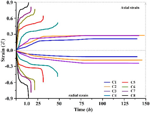
Figure 2. Strain-time curves of rock samples in the WJRV group.
The C5 sample exhibits a unique oblique slip shear failure that results from a penetrating structural plane along the slip shear plane. This leads to optimal failure along this path. On the other hand, samples C6, C7, and C8 exhibit typical lateral tensive-shear failure from inside to outside, with the position of tensive-shear failure occurring in the direction of the lamellar structure facing the free plane. Specifically, the tensive-shear failure position of rock samples C6 is located at the lower position of the bedding plane, while the tensile and shear failure of the bedding plane of C7 and C8 samples are in the middle and upper part of the bedding plane. The broken bedding plane falls off layer by layer, resulting in a transverse conical cavity with larger outer diameter and smaller inside diameter, with stepped rock steps left in the upper and lower positions of the conical cavity. The suspended inverted rock steps occurring in the upper position can be described as a suspended plate structure with unconstrained front end and fixed back end. When this phenomenon occurs in the field and the scope is large, the suspension plate structure is very likely to produce shear failure along the internal structural plane and vertically fall off, posing a major safety hazard for mining.
To ensure the reliability and universality of the experiment, five groups of samples of the same type were included in the creep test. The results were found to be consistent, with failure and instability occurring when the layered sandstone is subjected to more than 60% of its own uniaxial compressive strength during creep.
3 Failure characteristics of roadway analysis using physical similarity simulation
3.1 Preparation for the experiment
Physical model experiment combined load simulation experiment platform was designed, which can realize single independence and the combined surface-active load. The thermal infrared monitoring system was used to observe and record the migration and distortion information of the local temperature anomaly area on the model surface. Meanwhile, acoustic emission monitoring system was used to collect signal of acoustic energy rate in the process of rock failure, so as to realize the real-time comparison analysis of acoustic and thermal matching. The model size was 155.0 cm × 25.0 cm × 100.0 cm, geometric similarity ratio was 100.0, bulk density similarity ratio was 1.2, stress similarity ratio was 12.0. The coal seam buried depth is 380.0 m, so the initial stress in the vertical direction should be δV= 7.9 MPa. Considering tectonic stress, lateral pressure coefficient λ*=1.2, so the initial horizontal stress should be δH= 9.4 MPa. But, because the upper goaf, it should be considered when calculating the initial stress. Finally, we determine the vertical direction of the initial stress is δV=2.1 MPa, the initial stress in the horizontal direction should be δH= 2.5 MPa.
Mica powders are adopted to simulate rock structural plane interval, the trenchless disturbance zone around the model allows single layer thickness more than 3.0 cm. The excavation disturbance zone of single layer thickness is 2.0 cm. The sensitive area of single layer thickness is 1.0 cm. The simulated materials include coal powder, river sand, gypsum, white powder and water. The density of rock-like material is considered as 1.6 g/cm3. According to Formula Cσ=ClCγ, the mass of rock-like material consumed for paving experiment frame 1.0 cm is 6.2 kg. The bulk density and stress similarity coefficients of various lithologies were obtained (Table 1). The parameters of numerical calculation are shown in Table 2 and Table 3.
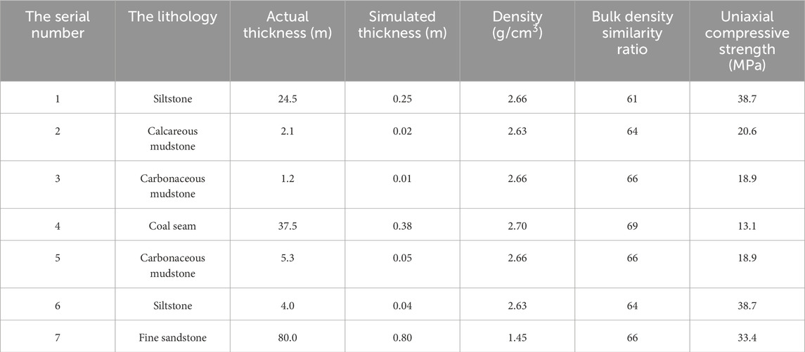
Table 1. Model stratification and related material parameters.
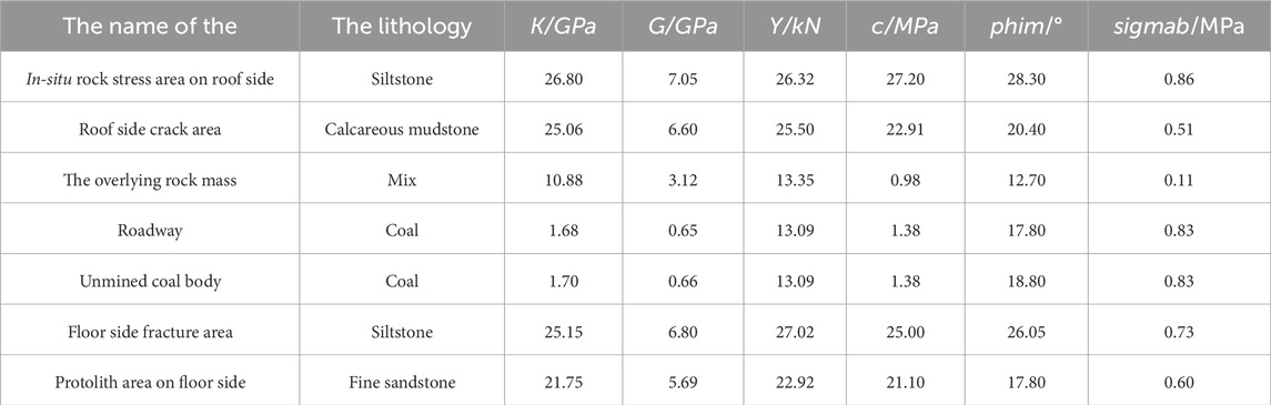
Table 2. Numerical model calculation of non-aging parameters.

Table 3. Calculation parameters of creep of numerical model.
The design of the combined loading simulation experimental platform is shown in Figure 3.
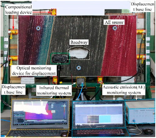
Figure 3. Simulation experimental platform of plane combined loading.
3.2 Physical model experimental results and analysis
The deformation and instability process includes four stages:
(1) During the first phase of the experiment, the horizontal and vertical stresses were measured to be 2.1 MPa and 2.5 MPa, respectively. At this stage, the model experienced elastic deformation, and the acoustic emission signals gradually weakened. The model contracted inwards with a decreasing shrinkage rate. Eventually, a transverse elastic deformation of about 1.2 cm and a vertical elastic deformation of 1.6 cm were generated. It is noteworthy that during this process, weak heat emission was detected at the edge of the model by thermal infrared imaging (Figure 4).
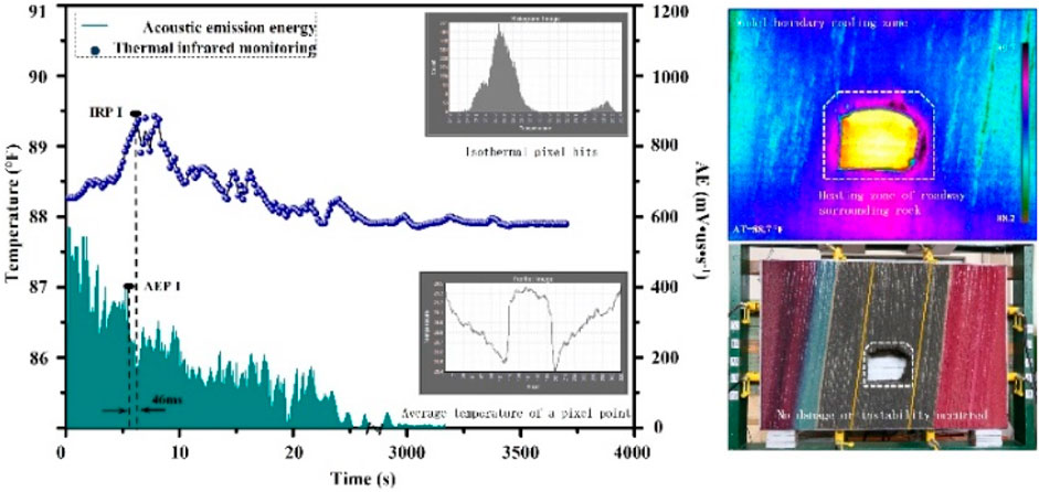
Figure 4. Monitoring results of the first stage.
After the initial elastic deformation process, the model enters the plastic deformation stage, resulting in a rise in AE signals and an increase in their number until reaching the first peak point (AEP i), followed by a gradual decline. Thermal infrared imaging reveals that the edge of the model experiences a gradual heating up during the initial stages of stress. After the AE peak appears after 46 ms, the edge region of the model reaches the first thermal infrared peak (IRP i), before beginning to cool down. During the stable phase, the stress is kept constant, and the variation characteristics of AE and thermal infrared parameters are monitored until they stabilize. This phase lasts for around 1.0 h. The activity of various signals is highest when stress is applied within 25.0 s, after which it enters a stable state. When stress is applied to a coal-rock mass in a roadway, infrared monitoring indicates that the temperature of the left and right sides of the roadway experiences a sudden rise and fall. However, since the stress applied is small, the coal-rock mass in the roadway is not significantly affected, resulting in no breakage or instability of the coal or rock in the roadway.
(2) Once the applied stress level reached the initial ground stress level and stabilized, the horizontal and vertical stresses were loaded to 3.2 MPa and 3.7 MPa, respectively. The model experienced plastic deformation and continued to move inwards, with a high initial moving speed that gradually decreased towards a static state. The deformation produced lateral displacement of approximately 0.8 cm and vertical displacement of 1.1 cm. Local creep was observed in the two sides and top of the roadway, causing minor fall-offs of coal-rock masses due to the uncoordinated deformation of the coal-rock mass. However, there was no large-scale damage or instability of the coal and rock.
During the second loading phase, the AE signals were dense and showed an exponential upward trend. However, when the AE reached the second peak (AEPII), the signal decreased rapidly and eventually entered a low-frequency energy gathering period. At this stage, the joints and fractures in the model tended to develop at a slower rate, while coal and rock masses accumulated energy and deformed. The stress was converted into two types of energy—energy consumed by the deformation of the model and elastic-plastic deformation energy stored in the coal and rock mass. As the stored energy threshold reached the failure limit of the coal and rock mass, failure occurred, resulting in instability of the coal and rock mass.
The thermal infrared monitoring results showed that during the secondary stress loading phase, the model exhibited plastic deformation at the edge, leading to a temperature rise at the corresponding position. Due to the model’s energy and heat exchange process with the environment being short, there was a transient temperature rise phenomenon observed. During localized creep of the coal and rock surrounding the roadway, there was a significant temperature rise, indicating the existence of accumulated energy under the influence of high stress levels. This points to a serious tendency towards failure (Figure 5).
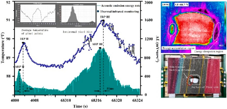
Figure 5. Monitoring results of the second stage.
During the constant pressure stage, numerous acoustic emission signals are recorded, some of which are marked by significant events. Thermal infrared monitoring results indicate a frequent and intense temperature rise phenomenon in the coal and rock part of the roadway, which is the focal point of creep. At 35 ms before the nearly vertical rock mass fracturing, the AE signals reached the third peak point (AEP III) instantaneously. Concurrently, thermal infrared imaging showed that the local rock mass on the roof side of the model began to undergo temperature rise after the application of stress and reached the third thermal infrared monitoring peak point (IRP III), forming the heat radiation zone, 57 ms after the occurrence of the second peak point of the AE.
The heat radiation that occurs during creep is a result of the internal stress of the rock mass. As creep progresses and additional load disturbances occur, the coal and rock approach their fracture threshold and become unstable. This leads to local buckling and energy release, which occurs in the creep concentration area and is responsible for the heat radiation. In the model, the creep concentration area is located in the middle of the coal-rock free surface, with a horizontal distance of 1.8 m from the coal-rock free surface. The rock mass on the floor side has an advantage in terms of stress environment, with micro-creep and crack expansion occurring in response to the applied stress, leading to slow heat release. After heat dissipation, the temperature in this area on the model surface is lower than the average temperature, resulting in the formation of a heat dissipation area.
(3) During the unstable process of creep and co-buckling deformation of coal and rock on the roof side, the model remains in a constant pressure state. After dissipation of energy, the region enters a thermal inactive state, forming an energy dissipation zone. Over time, the model continues to experience slight aging coal and rock deformation, resulting in a decrease in the AE signals. However, the load stress is partly dissipated through work or stored by the coal and rock, leading to an increased failure tendency of the roadway coal and rock. Thermal infrared monitoring results show energy transitions occurring on the model surface.
After 1,578 s from the end of acoustic emission, the model experienced creep and failure of the coal and rock in the roof side instability phase. During this period, deformation of the coal and rock began to occur at the bottom side, and acoustic emission monitoring showed that cracks were generated and developed in the coal and rock roadway. While some of the stress was consumed, most of the stress was converted into internal energy of the coal and rock, stored in the form of viscoplastic strain energy (Figure 6). When the stored energy reached its failure threshold, the coal and rock on the floor side experienced shear slip, starting from 0.25L distance from the bottom of the roadway (where L represents the height of the straight wall arch of the roadway).
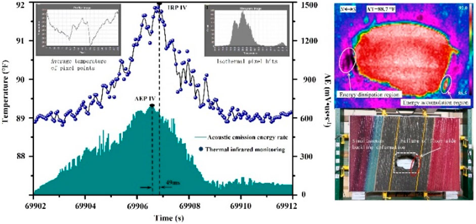
Figure 6. Monitoring results of the third stage.
During the instability of coal and rock on the bottom side of the roadway, the acoustic emission signals display a high degree of richness and indicate a higher internal fracture development degree of coal and rock. After the start of the AE energy rate, the experimental peaked at 68,317 s and then quickly dropped to the average level. The slope of the increase phase is less than that of the decline phase, which indicates a long time of energy accumulation and an instantaneous energy release. Thermal infrared monitoring revealed that during the creep process, the coal and rock on the boundary were mostly in a state of energy dissipation, with the bottom side of the roadway storing energy. When the stored energy exceeded the instability threshold of the coal and rock, instability occurred, spanning a width of 1.9 m at the bottom of the roadway. 27 ms before the shear fracture of the rock mass, the AE reached the fourth peak point (AEP IV) instantaneously. After a temperature-rise process of 49 ms, the temperature of the local rock mass at the bottom of the coal free surface increased to the fourth infrared monitoring peak point (IRP IV), forming a heat radiation zone. The horizontal distance between the heat radiation zone and the free surface of the coal and rock is 0.8 m. In the process of coal and rock deformation and dynamic instability, local temperature-rise and acoustic emission energy rate jumps occur, with the AE peak time being 16–18 ms earlier than rock fracture. This provides a basis for locating coal and rock stress concentration and disaster warning caused by instability through AE and thermal radiation area (Figure 7).
(4) After the deformation and shear sliding instability stage in the coal and rock roadway bottom side, the model remained in a constant pressure state. The residual strength of the coal and rock in the roof and floor of the roadway prevented widespread damage from occurring in the model. However, the model continued to undergo internal lateral contraction, overall volume shrinkage, and deformation and failure of the coal and rock on the sides of the roadway towards the inside of the roadway. These effects led to intense deformation of the top coal and rock, as well as a wide range of coal and rock deformation accumulation caused by aging and strong degree of coal rock instability. Ultimately, the deformation and failure of the coal and rock roadway cross-section caused upheaval and a sharp decrease in section size.
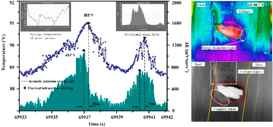
Figure 7. Monitoring results of the fourth stage.
After the failure and instability of the coal and rock on the floor side, the AE signal drops rapidly to the average level, indicating that damage cracks of varying sizes and directions continue to emerge in the roadway coal and rock under the action of stress. Thermal infrared monitoring shows that, after the instability and destruction of the coal and rock roadway bottom side, the region becomes an energy dissipation zone in which the boundary coal and rock is in a state of energy savings under constant pressure. Before the energy releases during instability, there is no occurrence of temperature jump phenomenon, indicating that the model was in a state of energy equilibrium.
The top of the coal and rock roadway experienced instability after the instability of the coal and rock on the bottom side, occurring after 23.5 s. Prior to the instability, the acoustic emission monitoring signals remained at average levels, with occasional significant events. This indicates that the process can be considered as energy savings. As the accumulated energy exceeded the coal and rock failure threshold, the coal and rock at the top of the roadway began to fail, resulting in a sharp increase in the number of AE events and energy rate. After 3.5 s, the unstable coal and rock fell into the roadway and accumulated on the floor, reaching the fifth peak point (AEP V) in AE. After that, the remaining coal and rock at the top of the roadway continued to collapse in a large range at 4.3 s, occupying the roadway internal space completely, with the acoustic emission reaching the sixth peak point (AEP VI).
The thermal infrared monitoring data shows that the coal and rock at the boundary of the model have undergone a creep process, and energy is consumed or lost before the coal and rock at the top of the tunnel are destroyed and unstable. Most of the coal and rock at the boundary are in a state after energy dissipation, without any temperature jumps, indicating that the energy is accumulating currently. The fifth and sixth peak points of thermal infrared (IRP V and VI) appear after the corresponding peak points of acoustic emission, and the intensity of the sixth peak point is weaker than that of the fifth peak point due to the smaller collapse range of coal and rock at the top of the roadway. Subsequently, the model enters the process of temperature drop again, and the surface temperature of the model returns to normal room temperature (Figure 8).

Figure 8. Dynamic aging characteristics of roadway rock mass deformation.
Based on the monitoring results, it has been observed that when rock mass in nearly vertical coal seam roadway undergoes initial compression, the strain effect of coal and rock is limited to a range of elastic-plastic deformation, and the failure and instability of coal and rock in roadway does not occur. However, as stress increases and loading time extends, local creep of coal rock occurs on both sides and the top of the roadway leading to the coal rock in the face of air falling off in a small range. Subsequently, the rock mass on the side of the roof begins to add bending deformation to the direction of the free surface of the roadway layer by layer. The mode of deformation is co-buckling, starting from the central position of the free surface of coal and rock. As stress transfers and accumulates, the coal and rock on the floor side become unstable and get destroyed, and the shear slip phenomenon starts from the foot position of the free surface of coal and rock. Finally, the coal and rock at the top undergo severe deformation, leading to large-scale and intense coal and rock instability disaster due to the accumulation of creep. This deformation and destruction of coal and rock in the roadway results in drastic changes to the cross section of the roadway, which undergoes significant reduction.
In subsequent research, numerical calculations were conducted to verify the accuracy of the simulated physical simulation results.
4 Numerical analysis of sandstone creep instability based on viscoelastic-viscoplastic model
4.1 Construction of numerical model
A numerical calculation model of coal rock has been developed using 3 Dimensions Distinct Element Code (3DEC). The coal seam is observed to be in the state of south pressure north with an average dip angle of 87°. To construct the coal seam roadway, the ratio of the model and the prototype is 1:1. The overall length of the model is 25.00 m, the vertical height is 17.00 m, and the strike advance distance is 25.00 m. The roadway is arched with straight walls, having a width of 3.30 m, and a distance from bottom plate to vault of 2.95 m. Due to significant mining activities, both the fracture zone and disturbance zone in the roadway have been greatly disturbed, hence considered as the “mining disturbance zone” in the numerical model, with a measured disturbance range of about 9.1 m on the north side and 10.5 m on the south side.
A 5.6 MPa roadway upper rock mass was applied to the surface model, with a simulated lateral horizontal stress of 6.7 MPa roadway. In order to consider the effect of mining disturbance on the roof rock mass, a microseismic monitoring system was installed within a certain range of rock mass inside the coal mining working face. The monitoring system records the disturbance caused by mining to the surrounding rock mass. By using the microseismic signal analysis method to eliminate clutter, the main disturbance waveform was analyzed. The main disturbance wave was processed through Fourier transform and error analysis was carried out by fast timing synchronization algorithm. A horizontal sinusoidal dynamic load with a frequency of 8.1 Hz was applied to the nodes inside the model working face partition.
To convert the acceleration time history into the stress time history, the built-in FISH function “int. FIS” was called. The viscoelastic-viscoplastic model with a damping ratio of 0.05 and Rayleigh damping as the mechanical damping form was used in numerical calculation. Rolling boundary conditions were implemented around the model to limit lateral and bottom displacement. The viscoelastic-viscoplastic model and the coulomb sliding model features of discontinuous discontinuities were assigned to model blocks using FISH function compilation. To simulate the stratified structural characteristics in the roadway wall rock mass, a set of structural planes were generated for the roadway wall rock mass with an interval of 0.2 m. The number of structural planes on the north side and south side of the roadway were 12 and 14 layers, respectively. In order to reduce model interference factors, the behavior of the coal and rock sub-blocks at the top of the roadway separating from the parent was released. The displacement constraints between the coal and rock sub-blocks on both sides of the roadway and the parent were released as well to monitor the model stress-strain fluctuation characteristics more clearly.
4.2 Analysis of numerical model calculation results
4.2.1 Shallow coal rock shedding stage
The coal and rock on both sides of the roadway roof and floor begin to deform and collapse under the comprehensive action of vertical and horizontal dynamic loads, with complete collapse observed when the calculation step reaches 21,275. As the coal and rock in the range of mining disturbance form fracture zones with low internal strength, the mechanical structure of the coal and rock becomes a unilateral opening force, leading to a caving behavior towards the free surface direction under the coupling disturbance of its dead weight and static and dynamic load. This behavior causes coal and rock to strip layer by layer from the parent coal and rock and accumulate in the roadway floor. The coal and rock far away from the roadway surface, however, retain good integrity and bear the majority of the vertical dynamic load. The main factors triggering the collapse of coal and rock on the surface are the dead weight of coal and rock, along with the horizontal dynamic load (Figure 9).
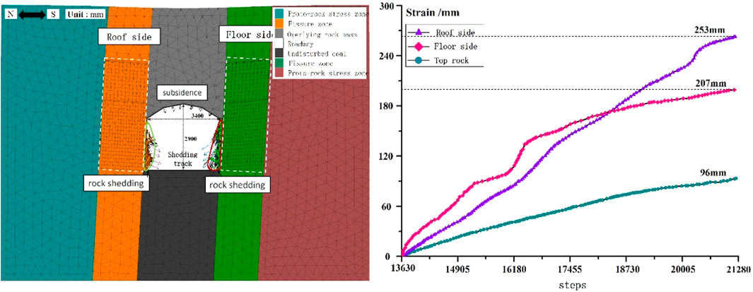
Figure 9. Results of the first stage of numerical model calculation.
The comprehensive stress in the coal and rock roadway begins to produce subsidence deformation when the calculation steps reach 13,687. The deformation rate of the coal and rock is slow in the beginning and is characterized by a layered structure of coal and rock deformation, with changes occurring in the direction of the structure plane. As the stage progresses, the top coal and rock remain stable. The data from monitoring both sides and the top of the coal rock roadway are analyzed, and it is observed that the displacement rate decreases rapidly with lateral displacement while the vertical displacement rate increases. The maximum lateral displacement of outer coal and rock on the roof side is 253 mm, and the maximum lateral displacement of outer coal and rock on the floor side is 207 mm. The maximum subsidence of coal rock at the top of the roadway is 96 mm. Although the deformation and caving behavior characteristics of coal rock are not obvious at this stage, it is speculated that most of the deformation produced by coal rock is elastic-plastic deformation, with creep accounting for a small proportion due to the short loading time.
4.2.2 Small deformation stage of coal and rock on floor side
Following the deformation of coal and rock on the floor side, a portion of the stress transfers to the coal and rock on the roof side, resulting in a rise in strain rate on the roof side and an improvement in stress state on the floor side. The strain rate of coal and rock on the floor side gradually decreases, but the strain continues to increase. The calculation step reaches 24,500 when the strain rate of coal and rock on the floor side reaches its minimum value of 1.6 mm/102 steps, marking the end of the second stage of the calculation time limit. The roadway’s two sides in coal and rock surface has caved in the bottom due to the action of gravity, with the load being transferred down to the two coal and rock formations. Due to the mechanical structural differences and horizontal force imbalances, the shallow part of the bottom side is prone to slip deformation and instability along the direction of the bedding structure of the coal and rock formation. Additionally, dynamic loads can cause further deterioration of the force environment, leading to separations of rock (Figure 10).
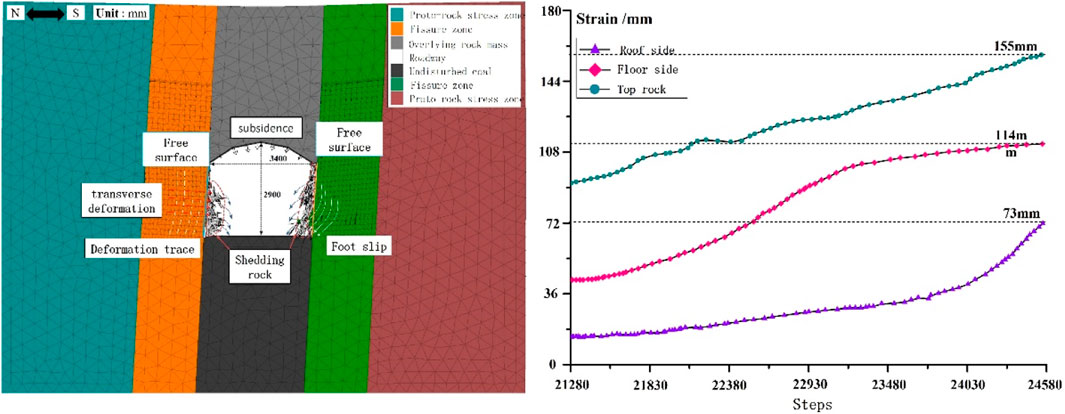
Figure 10. Results of the second stage of numerical model calculation.
In contrast, the structure of coal and rock on the side of the roof is more difficult to deform. The stress function of coal and rock on the roof side is influenced by the conduction function, resulting in a lateral unbalanced stress state of coal and rock. However, this also causes the stress environment at the bottom side of the coal and rock to improve, while the stress state of coal and rock on the roof side begins to deteriorate. As a result, the overall coal and rock on the roof side undergoes transverse deformation towards the free surface, with the center of deformation overlapping with the center of gravity of coal and rock. During this stage, the coal and rock on the roof side only undergoes deformation along the time axis without any damage or instability.
Displacement monitoring points were set on the sides and top of the deep coal and rock roadway. Analysis of the deformation rule and rate of coal and rock on the roof and bottom sides revealed that the deformation rate tends to be gentle at first before rapidly increasing and gradually evolving thereafter, with final shape variables of 73 mm and 114 mm respectively, exhibiting polarized development characteristics. The coal and rock at the top experienced subsidence deformation at a low rate, with a cumulative shape variable of 155 mm. However, under the action of comprehensive stress, the coal and rock on the floor side continued to undergo small rates of creep without wide-ranging stratification and slip failures. The coal and rock at the top continued to move down at a low rate, compressing the area of the roadway cross-section, but the degree of change was small at this stage, and it is unlikely to affect its normal functioning.
4.2.3 Cobuckling stage of coal and rock on roof side
It has been observed that the lateral deformation of coal and rock on the sides of the roadway has significantly increased, especially on the roof side where it starts from the outermost layer of the structured matrix. The deformation rate on the roof side is reported to be around 360 mm and 3.1 mm/102, while on the floor side, the deformation amount and rate are 247 mm and 2.1 mm/102, respectively (Figure 11). The layered structure of coal rock on the roof side causes it to produce complementary bending deformation and shear fracture, which extends from the outside to the inside under the influence of comprehensive stress that includes dead weight and dynamic load disturbance. The outermost layered structure on the roof side is in the state of circumferential force and unilateral air force, which makes it highly susceptible to transverse shear failure along the central position of coal and rock structure of the roadway, especially under the disturbance of transverse dynamic load. To analyze this, a cartesian coordinate system was established using the intersection point of the original coal rock free surface and the transverse shear failure surface on the roof side, where the cross section curve of the transverse shear failure surface was expressed as Y = −0.074x, and the intersection point of the coal rock free surface and the transverse shear failure surface was found to be 1,087 mm away from the bottom plate.
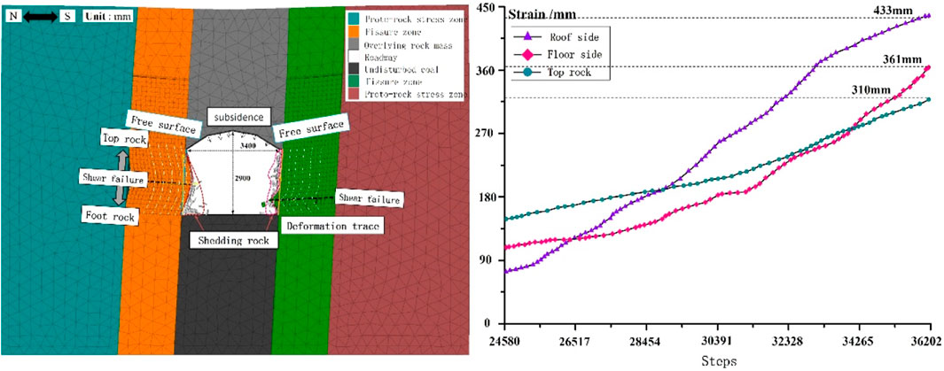
Figure 11. Results of the third stage of numerical model calculation.
Once the coal rock on the shear failure surface loses support from the deformed coal rock below it, the lower part and side of the free surface are left without support. The vertical action of coal rock and dead weight on top leads to the slide and instability of the coal rock along the structure facing the lower space. Under the action of comprehensive stresses such as coal rock, dead weight, and transverse dynamic load, stepped shear failure along the transverse fracture occurs. As a result, the coal rock above the horizontal shear failure plane exhibits an inverted step-type shear failure, while the coal rock below exhibits a step-type shear cross-layer shear failure, with failure range increasing from inside to outside.
The coal and rock on the floor side continue to exhibit creep, which leads to the generation of transverse shear failure surfaces within the coal and rock mass. The expression for the cross-section curve of the transverse shear failure surface is given as Y = 0.053x with an intersection point 500 mm away from the bottom plate. Due to the presence of unilateral adverse stress along the bedding plane direction, the outermost layers of coal and rock experience stress leading to shear sliding instability. While the stratified coal and rock are initially in a state of internal force balance, the overall aging and deformation trend analysis indicates that, under the effect of comprehensive strength, combined with the time effect of coal and rock on the bottom side, instability is eventually produced.
4.2.4 Foot slip stage at floor side
During the deformation process of the coal and rock, some stress was transferred to the bottom side, and the coal and rock roadway reached its deformation limit. At calculation step 53,500, the coal and rock experienced an overall fall and instability, which resulted in the complete loss of its function as a roadway. The deformation caused sides of the roadway to converge substantially to the interior, and three displacement monitoring points were used to track this movement. It was found that the coal and rock on both sides moved closer by 1,846 mm, consistent with field measurement results. However, there were differences in the position of deformation and breakage modes on both sides of the coal and rock. The lateral deformation of the coal and rock on the roof initially manifested as meticulous buckling, starting from the central position of the roadway and with the biggest shape variable close to 710 mm. This was due to the predominantly tensile stress environment under the action of the weight comprehensive state on the vertical position of the lower part of the coal and rock roadway roof side, which was excavated for roadway construction. Additionally, the large dip angle (about 87°) of the coal and rock roadway sides resulted in the vertical compressive stress less than its internal layered structure surface strength, which was not enough to cause abscission of the hierarchical structure of the coal and rock. The outer layer of the roadway on both sides experienced compressive stress and obvious plastic deformation of coal. Under the influence of time effect, the creep of coal and rock on the roof side started from the central position of the roadway wall and the yield deformation grouped from inside to outside direction of the free surface leading to the phenomenon of co-buckling of roadway rock mass, produced by the combination of vertical compressive stress and lateral horizontal stress (Figure 12).
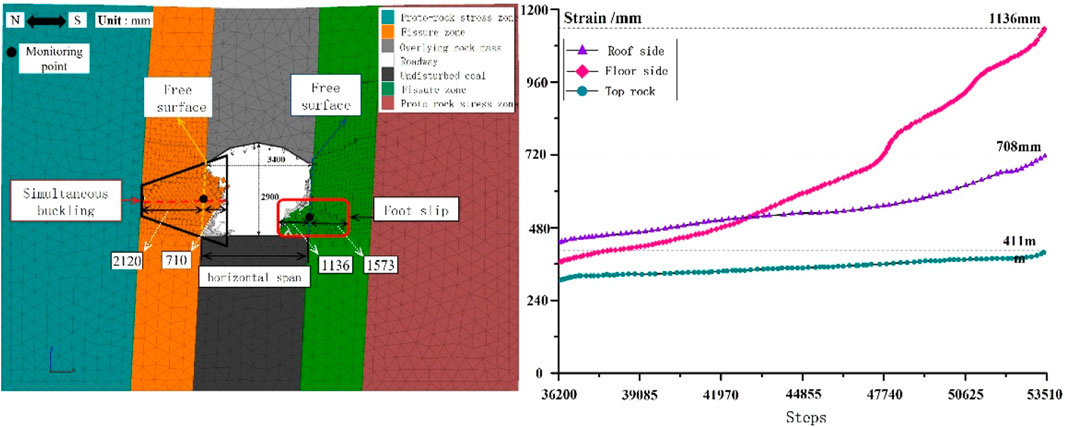
Figure 12. Results of the fourth stage of numerical model calculation.
Under the disturbance of mining stress and the action of the rock column between coal seams, the stress environment of coal and rock deteriorates further, leading to the peeling-off layer by layer behavior of the coal and rock. Deformation performance was observed to begin on the bottom side of the lane with the largest variable of 1,136 mm due to the supporting function of the vertical position of the occurrence of coal and rock on the lower part. Over time, once the comprehensive stress exceeds the strength of the coal-rock structural plane, a shear slip plane occurs along the structural plane, and the rock mass layered on the shear slip plane slides along the slip face inside the roadway. This leads to the overall shear sliding instability of the coal and rock on the bottom side, resulting in rock mass accumulation in the roadway floor. The total internal deformation of coal and rock instability on both sides of the roadway reached 1,846 mm, accounting for 54.3% of the transverse length of the roadway, which seriously affected its normal function.
The length of the broken bedding plane gradually decreases from the outside to the inside. This results in the formation of a large lateral conical cavity on the outer side of the coal and rock mass and a small one on the inside. Step-like rock steps are left in the upper and lower positions of the conical cavity. The steps at the upper position can be simplified as a front-end unconstrained, back-end clamped hanging plate structure. Under the influence of gravity, the hanging plate structure is likely to generate shear failure along the internal structure surface, leading to vertical peeling, which poses significant hidden danger for field security operations. The compression test results of the coal and rock mass show high consistency with this observation.
5 Conclusion
(1) It has been observed that the layered sandstone in the study area exhibits creeping behavior when it experiences over 60% of its uniaxial compressive strength. This may lead to subsequent failure and instability. Vertical ladder tension-shear failure and oblique slip shear failure are the main forms of failure, and sometimes these two failure forms can occur in combination.
(2) Both physical modeling experiments and numerical calculations have demonstrated that the lateral limitation of rock mass deformation and destruction of roadway roof coal and rock occur at the central position of synthetic buckling and the shearing destruction, while the limitation of coal and rock deformation and destruction on the roadway bottom side occur at the free surface of the base shear sliding failure. This results in an asymmetric instability phenomenon of coal and rock roadway.
(3) According to theoretical mechanics calculations, the maximum bending moment of the roof of a coal rock roadway is concentrated on the nearly vertical side and near the middle of the coal rock structure, making it prone to lateral shear failure at that location. On the other hand, under the influence of comprehensive stress, the bottom of the coal rock structure is prone to shear sliding failure, resulting in asymmetric instability of the coal rock roadway.
Data availability statement
The original contributions presented in the study are included in the article/Supplementary material, further inquiries can be directed to the corresponding author.
Author contributions
PB: Supervision, Writing–original draft. ZL: Writing–original draft. CY: Writing–review and editing. EL: Validation, Writing–original draft. HG: Software, Writing–review and editing. YX: Validation, Writing–original draft. ZY: Writing–review and editing.
Funding
The author(s) declare that no financial support was received for the research, authorship, and/or publication of this article.
Acknowledgments
A special acknowledgement should be shown to the reviewers for their constructive and valuable comments. Thank them for their guidance in their busy schedule.
Conflict of interest
Authors PB, ZL, CY, EL, HG, and YX were employed by Shaanxi Huadian Yuheng Coal Power Co., Ltd.
The remaining author declares that the research was conducted in the absence of any commercial or financial relationships that could be construed as a potential conflict of interest.
Publisher’s note
All claims expressed in this article are solely those of the authors and do not necessarily represent those of their affiliated organizations, or those of the publisher, the editors and the reviewers. Any product that may be evaluated in this article, or claim that may be made by its manufacturer, is not guaranteed or endorsed by the publisher.
References
Baud, P., Heap, M. J., Meredith, P., Bell, A., and Main, I. (2009). Time-dependent barittle deformation in darley dale sandstone.
Bhasin, R., and Grimstad, E. (1996). The use of stress-strength relationships in the assessment of tunnel stability. Tunn. Undergr. Space Technol. 11, 93–98. doi:10.1016/0886-7798(95)00047-x
Bing, G., Tao, Z., Thusyanthan, I., and Chunan, T. (2024). Modelling rock fracturing by a novel implicit continuous to discontinuous method. Comput. Geotechnics 166, 106035. doi:10.1016/j.compgeo.2023.106035
Bozzano, F., Della Seta, M., and Martino, S. (2016). Time-dependent evolution of rock slopes by a multi-modelling approach. Geomorphology, 263. doi:10.1016/j.geomorph.2016.03.031
Brückl, E., and Parotidis, M. (2005). Prediction of slope instabilities due to deep-seated gravitational creep. Nat. hazards earth Syst. Sci. 5, 155–172. doi:10.5194/nhess-5-155-2005
Cornet, J., Dabrowski, M., and Schmid, D. W. (2018). Long term creep closure of salt cavities. Int. J. Rock Mech. Min. 103, 96–106. doi:10.1016/j.ijrmms.2018.01.025
Fabre, G., and Pellet, F. (2006). Creep and time dependent damage in argillaceous rocks. Int. J. Rock Mech. Min. 43, 950–960. doi:10.1016/j.ijrmms.2006.02.004
Gratier, J.-P., Guiguet, R., Renard, F., Jenatton, L., and Bernard, D. (2009). A pressure solution creep law for quartz from indentation experiments. J. Geophys. Res. 114. doi:10.1029/2008jb005652
Grgic, D., and Amitrano, D. (2009). Creep of a porous rock and associated acoustic emission under different hydrous conditions. J. Geophys. Res. Solid Earth 114, B10201. doi:10.1029/2006jb004881
Herrmann, J., Rybacki, E., Sone, H., and Dresen, G. (2020). Deformation experiments on bowland and posidonia shale—Part II: creep behavior at in situ pc–T conditions. Rock Mech. Rock Eng. 53, 755–779. doi:10.1007/s00603-019-01941-2
Huicong, X., Xingping, L., Pengfei, S., Yang, Y., Zhang, S., Yan, B., et al. (2023). Energy dissimilation characteristics and shock mechanism of coal-rock mass induced in steeply-inclined mining: comparison based on physical simulation and numerical calculation. Acta Geotech. 18, 843–864. doi:10.1007/s11440-022-01617-2
Leite, M. H., Ladanyi, B., and Gill, D. (1993). Determination of creep parameters of rock salt by means of an in situ sharp cone test. Int. J. Rock Mech. Min. Sci. Geomechanics Abstr. 30, 219–232. doi:10.1016/0148-9062(93)92725-6
Lianpeng, D., Yishan, P., Zhonghua, L., et al. (2021). Quantitative mechanism of roadway rockbursts in deep extra-thick coal seams:Theory and case histories. Tunn. Undergr. Space Technol., 1–14. doi:10.1016/j.tust.2021.103861
Miura, K., Okui, Y., and Horii, H. (2003). Micromechanics-based prediction of creep failure of hard rock for long-term safety of high-level radioactive waste disposal system. Mech. Mater. 35, 587–601. doi:10.1016/s0167-6636(02)00286-7
Nadimi, S., Shahriar, K., Sharifzadeh, M., and Moarefvand, P. (2011). Triaxial creep tests and back analysis of time-dependent behavior of Siah Bisheh cavern by 3-Dimensional Distinct Element Method. Tunn. Undergr. Space Technol. 26, 155–162. doi:10.1016/j.tust.2010.09.002
Oohashi, K., Hirose, T., Kobayashi, K., and Shimamoto, T. (2012). The occurrence of graphite-bearing fault rocks in the Atotsugawa fault system, Japan: origins and implications for fault creep. J. Struct. Geol. 38, 39–50. doi:10.1016/j.jsg.2011.10.011
Ozsen, H., Özkan, İ., and Sensogut, C. (2014). Measurement and mathematical modelling of the creep behaviour of Tuzköy rock salt. Int. J. Rock Mech. Min. 66, 128–135. doi:10.1016/j.ijrmms.2014.01.005
Pan, Y., Pengfei, S., Huicong, X., Jiageng, C., Zhiyong, L., and Haoqiang, S. (2024). Experimental study on mechanical damage characteristics of water-bearing tar-rich coal under microwave radiation. Geomechanics Geophys. Geo-Energy Geo-Resources 10, 3. doi:10.1007/s40948-023-00726-w
Pellet, F., and Fabre, G. (2007). Damage evaluation with P-wave velocity measurements during uniaxial compression tests on argillaceous rocks. Int. J. Geomechanics 7, 431–436. doi:10.1061/(asce)1532-3641(2007)7:6(431)
Rahimi, S., and Hosseini, M. (2014). Laboratory studies of creep behavior on thick-walled hollow cylindrical salt rock specimens. Arabian J. Geosciences 8, 5949–5957. doi:10.1007/s12517-014-1622-5
Rui, K., Tuncay, E., Ulusay, R., Xiwei, Z., and Xiating, F. (2021). An experimental investigation on stress-induced cracking mechanisms of a volcanic rock. Eng. Geol. 280, 105934. doi:10.1016/j.enggeo.2020.105934
Sharma, P., Prakash, R., and Abedi, S. (2018). Effect of temperature on nano- and microscale creep properties of organic-rich shales. J. Petroleum Sci. Eng. 175, 375–388. doi:10.1016/j.petrol.2018.12.039
Stead, D., and Wolter, A. (2015). A critical review of rock slope failure mechanisms: the importance of structural geology. J. Struct. Geol. 74, 1–23. doi:10.1016/j.jsg.2015.02.002
Wang, W., Liu, H.-X., Zhu, Q., and Shao, J. (2015). A micromechanics-based creep damage model for brittle rocks. Eur. J. Environ. Civ. Eng. 19, s1–s14. doi:10.1080/19648189.2015.1064616
Xianhui, F., Bing, G., Zhengzhao, L., Shanyong, W., Chun’an, W., Hong, L., et al. (2024). Study of the dynamic failure characteristics of anisotropic shales under impact Brazilian splitting. Rock Mech. Rock Eng. 57, 2213–2230. doi:10.1007/s00603-023-03673-w
Xingping, L., Huicong, X., Pengfei, S., et al. (2024). Research on mechanism of rockburst induced by mined coal-rock linkage of sharply inclined coal seams. Int. J. Minerals, Metallurgy Mater. 31. doi:10.1007/s12613-024-2833-8
Xu, Z., Bin, L., Youjun, X., Chenxu, Z., and Huachuan, W. (2023). Case study of performance assessment of overlapping shield tunnels with a small curve radius. Deep Undergr. Sci. Eng., 1–16. doi:10.1002/dug2.12066
Yanpeng, H., Wenyu, L., Zhiyu, F., Li, M., and Changkui, C. (2024). The basic characteristics of paste backfill materials based on highly active mineral admixtures: Part I. Preliminary study on flow, mechanics, hydration and microscopic properties. Process Saf. Environ. Prot. 187, 1366–1377. doi:10.1016/j.psep.2024.05.056
Yongyi, W., Bin, G., Chun’an, T., and Xiaoyu, Y. (2023). Size effect and lateral pressure effect on the mechanical resistance of columnar jointed basalt. Int. J. Rock Mech. Min. Sci. 171, 105571. doi:10.1016/j.ijrmms.2023.105571
Keywords: layered sandstone, creep, physical simulation, numerical calculation, nearly vertical
Citation: Bai P, Li Z, Yu C, Liu E, Gao H, Xie Y and Yan Z (2024) Experimental research on creep characteristics and failure mechanism of mining roadway in nearly vertical coal seams. Front. Earth Sci. 12:1425208. doi: 10.3389/feart.2024.1425208
Received: 29 April 2024; Accepted: 31 May 2024;
Published: 19 June 2024.
Edited by:
Bin Gong, Brunel University London, United KingdomReviewed by:
Huachuan Wang, University of Strathclyde, United KingdomJian Cao, Inner Mongolia University of Science and Technology, China
Copyright © 2024 Bai, Li, Yu, Liu, Gao, Xie and Yan. This is an open-access article distributed under the terms of the Creative Commons Attribution License (CC BY). The use, distribution or reproduction in other forums is permitted, provided the original author(s) and the copyright owner(s) are credited and that the original publication in this journal is cited, in accordance with accepted academic practice. No use, distribution or reproduction is permitted which does not comply with these terms.
*Correspondence: Peng Bai, NDE0NzIwNjYyQHFxLmNvbQ==