 Jie Hu
 Longfei Zhang2*
- 1Department of Geotechnical Engineering, College of Civil Engineering, Tongji University, Shanghai, China
- 2State Key Laboratory for Tunnel Engineering, China University of Mining and Technology, Beijing, China
This contribution focuses on understanding the bedding effect of coal rocks under the Brazilian splitting test. First, multiple Brazilian splitting tests were performed on coal rocks with various bedding angles to systematically investigate the influence of stratification. Subsequently, numerical models with stratified structures were constructed, and a continuous–discontinuous numerical analysis method based on the cohesive zone model (CZM) was employed to conduct the corresponding numerical investigations. Results indicate that the load–displacement curves of coal rock specimens with different bedding angles can be classified into four stages: initial compaction stage, elastic deformation stage, crack rapid coalescence stage, and final destruction stage. With increase in the bedding angle, the failure patterns of coal rock specimens can be categorized into three groups: 1) stretching damage along bedding planes; 2) mixed tension and shear failure along the bedding planes and the coal matrix; and 3) stretching failure passing through the coal matrix. Furthermore, the tensile strength and cumulative acoustic emission (AE) energy–displacement relations are significantly influenced by the bedding angle. The numerical model can effectively predict the mechanical responses and fracture behavior of coal rock specimens, providing empirical parameters for the simulation of similar rock engineering.
1 Introduction
Anisotropy is a considerable structural property for rocks with a wide distribution on the planet, such as slates, sandstones, shales, mudstones, and gneiss (Brown et al., 1981; Gao et al., 2015; Wu et al., 2016). It is also one of the most distinctive features that must be taken into account in rock engineering, mining, tunneling, gas extraction, petroleum engineering, and so on (Zhang, 2013; Hatzor et al., 2015; Nguyen and Le, 2015; Wang et al., 2017; Qin et al., 2019). In addition, crude oil, natural gas, coal-bed methane, and other fossil energy sources are generally stored in these rock masses with layer structure. Therefore, increasing attention has been paid to the anisotropic properties of rocks with layer structure in recent research (Tan et al., 2017; Park et al., 2018).
The tensile strength of rock-like materials is significantly lower than their compressive strength. In practical engineering, rock failure is often encountered due to tensile failure. Therefore, studying the tensile strength of rocks is of great importance for engineering safety. Brazilian splitting tests are an established method and suggested by the International Society for Rock Mechanics (ISRM) (Laboratory Tests, 1977) for indirectly determining the tensile strength of rocks, which is a critical parameter in geotechnical design and analysis. This test was first proposed by Lobo Carneiro and Barcellos during the Fifth Conference of the Brazilian Association for Standardization in 1943 (Rocco et al., 2001); therefore, it is named as the Brazilian splitting test or Brazilian test. These tests are relatively simple and economical compared to direct methods for determining tensile strength. For example, Cho et al. (2012) investigated three laminated rocks by Brazilian splitting tests. Their study showed that the existence of the bedding planes plays an important role in the global properties of rock specimens, especially when the orientation of the bedding planes is parallel to the principal stress, and the shear failure occurring along the bedding planes greatly affects the tensile strength, as evidenced by the Brazilian tensile tests. Tavallali and Vervoort (2010a) and Tavallali and Vervoort (2010b) also adopted Brazilian splitting tests to investigate the tensile strength and tensile fracture patterns of layered sandstone affected by layer orientation. Moreover, Heng et al. (2015a) and Heng et al. (2015b) studied the anisotropic properties of shale based on uniaxial and triaxial compression tests. Significant anisotropy characteristics including the compression strength, elastic modulus, and the final failure modes were observed. The fracture characteristics and mechanical behaviors of coal rocks and sandy mudstones subjected to uniaxial compression, indirect tensile test, and the semicircular bend tests were all discussed by Wu et al. (2016). The crack path and crack deviation angle have also been discussed by them based on crack propagation traces.
Moreover, with the great improvement in the computing power of personal computers, the numerical simulation method has become a powerful tool for systematically studying the aforementioned problem. For example, Xu et al. (2019) adopted the 2D particle flow code to investigate the influence of bedding planes on the global mechanical responses and local crack propagation of rocks with the characteristics of the transversely isotropic structure that is subjected to uniaxial compression. In their simulations, the behavior of the matrix was characterized by the flat joint contact model, and the bedding planes’ behavior was represented by a set of parallel continuous smooth joint contacts between particles. Accordingly, the effect of pre-existing cracks and strength, strength ratio, and the stiffness of smooth joint contact are all discussed in their previous study. Moreover, the extended finite element method (XFEM) was adopted by Suo et al. (2020) to predict the fracture process in cracked chevron notched Brazilian disc (CCNBD) specimens with different bedding angles. It is generally accepted that due to the shared nodes in the finite element mesh and adopting of continuous shape function to describe the continuous displacement field, the traditional finite element method (FEM) is not a useful approach for the simulation of typical fracture problems, while the discrete element method (DEM) always adopts rigid discs or spheres to simulate the structure of specimens approximately, which may lead to great differences with the real situation. The cohesive zone model (CZM) is a suitable tool to study the crack propagation for quasi-brittle materials, thus avoiding unrealistic stress singularities at the crack tip. For example, Jiang and Meng (2018) used the CZM to predict the mechanical characteristics and fracture process of homogeneous rocks under uniaxial compression and Brazilian splitting tests. The continuous–discontinuous numerical simulation method based on the CZM can simulate the elastic, damage, and fracture processes of materials under complex loads. It can also simulate the movement, collision, flow, and accumulation processes of broken granular materials, making it especially suitable for the whole process simulation of progressive instability and failure of rock. Therefore, this technique was also adopted in this study.
In practical engineering scenarios, the direction of rock bedding varies, leading to significant differences in the properties of rock mass. Consequently, it becomes essential to comprehend the mechanical properties and failure characteristics of rocks that correspond to different bedding angles. In addition, coal rock is also a typical layered rock, and it is widely used in all walks of life, not only as a primary fossil fuel but also a chemical raw material. With development of urbanization, the human society will consume more energy and chemical products. Accordingly, the mining scale will also increase, and hence rock bursts, roof falling, water gushing, gas explosion, and other coal mine disasters will garner more attention (Skoczylas and Wierzbicki, 2014; Guo et al., 2019; Ren et al., 2019; Zhang et al., 2019; Wang et al., 2020). In order to explore the tension behaviors of coal rocks and provide a reference for the engineering practice, it is particularly important to carry out in-depth research studies on coal rocks with different bedding angles.
In this study, coal rock was first collected from the working face. After coring, cutting, and polishing, these coal samples are processed into Brazilian disc specimens and divided into seven groups based on different bedding angles (α). The Brazilian splitting tests were carried out to study the influence of bedding angles on mechanical responses, failure process, and acoustic emission (AE) characteristics of coal rocks. At the same time, the CZM was used to describe the nonlinear mechanical behaviors and the fracture problem of coal rocks with different bedding angles based on the ABAQUS/Explicit platform. Finally, crack propagation paths, failure process, tensile strength, and AE characteristics of coal rocks were all investigated based on experiments and simulations.
2 Experimental study
2.1 Material source
The coal rock specimens used in the Brazilian splitting test were obtained from Hongyang Third Mine in the Liaoning Province, China. Raw coal was taken from the working face No. 1213 approximately 780 m below ground level. The coal sample has obvious bedding characteristics in the coal seam. The X-ray diffraction of the coal sample indicated the content of amorphous minerals (90.3%) and clay minerals (9.7%). In addition, main mineral components of clay minerals are illite and kaolinite.
2.2 Sample preparation
The disc-shaped specimen used in the Brazilian splitting test is commonly referred to as the Brazilian disc. The most commonly used dimensions for Brazilian disc specimens is diameter of 50 mm and thickness of 25 mm. This study also used Brazilian disc specimens of this size. The Brazilian disc sample is prepared as follows: the bulk raw coal collected at the working face was sealed to ensure that the coal rock remains in situ. First, wire cutting with a diameter of 50 mm was used for directional coring, as shown in Figure 1A. Then, the cylindrical coal samples were divided into Brazilian disc samples with a thickness of slightly more than 25 mm, as shown in Figure 1B. Finally, the discs were processed and polished into 25-mm-thick standard Brazilian disc samples. To ensure the accuracy of the experiments, the parallelism of the two end-faces was maintained within ±0.05 mm and the flatness within ±0.03 mm.
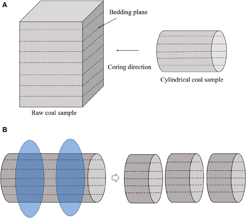
Figure 1. Preparation of Brazilian disc samples. (A) Directional coring diagram; (B) division into Brazilian discs.
In this paper, the bedding angle α is defined as the angle included between the principal stress and bedding planes, as illustrated in Figure 2A. To ensure the accuracy of the bedding angles during the experiments, the bedding direction was first marked on the specimen’s surface, passing through the center of the disc. A protractor was then used to measure and draw a straight line that intersected the center of the disc at an angle α to the bedding direction. When conducting the Brazilian splitting test, we must ensure that the straight line is consistent with the direction of loading. The processed Brazilian disc specimens were grouped according to the bedding angles (α = 0°, 15°, 30°, 45°, 60°, 75°, and 90°), as presented in Figure 2B. To ensure the reliability of the experimental results, at least three samples were included in each group. The processed samples were sealed immediately, and the test was completed within 1 week.
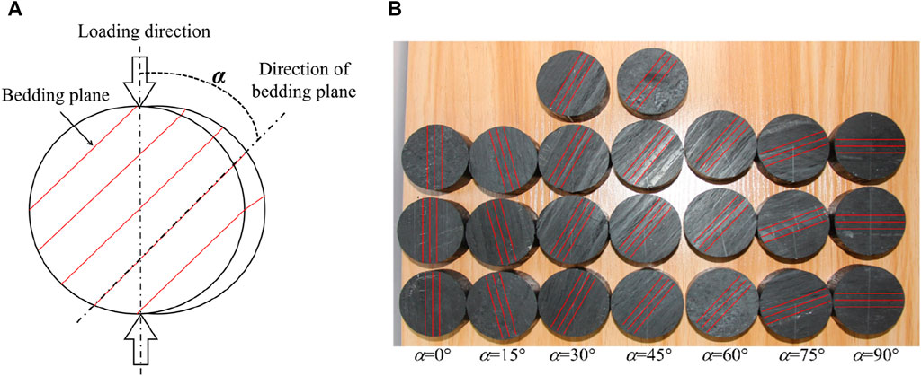
Figure 2. Brazilian splitting test samples. (A) Schematic of the Brazilian splitting tests; (B) Brazilian disc samples of coal rock under seven bedding angles.
2.3 Experimental equipment
Brazilian splitting tests were conducted using the nonlinear mechanical test system for deep soft rock and the special fixture for Brazilian splitting tests (Figure 3A), with a loading rate of 0.1 mm/min. The maximum axial load of the system is 500 kN, the measurement accuracy is less than 0.5%, and based on the American NI servo controller, high precision stable load can be applied. Moreover, a Micro-II system and the Nano-30 sensors designed by the American Physical Acoustics Corporation (PAC) were used for AE monitoring (Figure 3B). In this study, the threshold and sampling frequency were set as 40 dB and 10 kHz, respectively.
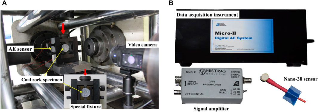
Figure 3. Experimental equipment. (A) Loading equipment; (B) AE test equipment.
2.4 Tensile strength
The tensile strength for the specimens with transversely isotropic structure characteristics can be obtained by using the Brazilian splitting test according to the expression by Claesson and Bohloli (2002). Indirect tensile strength correction coefficients for the seven angles (α = 0°, 15°, 30°, 45°, 60°, 75°, and 90°) are 0.8907, 0.9166, 0.9763, 1.0317, 1.0570, 1.0566, and 1.0525, respectively. In addition, the mean tensile strength values of coal rock with seven bedding angles are 0.720, 0.656, 0.614, 0.787, 0.973, 0.987, and 1.10 MPa, respectively, as illustrated in Figure 4. Due to the influence of internal factors such as mineral composition, gradation, porosity, and defects on the mechanical behavior and failure behavior of rocks (Wu et al., 2020; Peng et al., 2021; Wu et al., 2022; Wu et al., 2024; Zhao et al., 2024), there is some variability within each group.
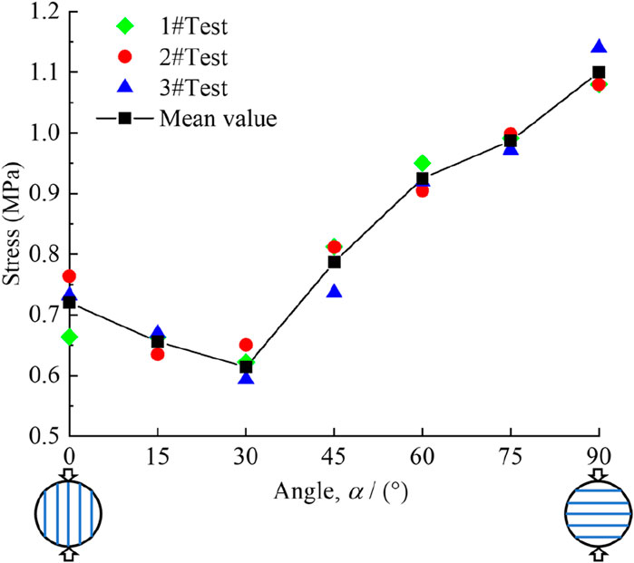
Figure 4. Tensile strength of coal rocks with different bedding angles.
Figure 4 demonstrates that the tensile strength of coal specimens varies over a wide range for different angles, indicating that bedding angles have a great effect on the tensile strength of coal rock specimens. The tensile strength of coal specimens first decreased (0°–30°) and then increased gradually (30°–90°). The minimum tensile strength occurs at α = 30°, while the maximum tensile strength occurs at α = 90°.
2.5 AE characteristics
For each bedding angle, the specimens whose ultimate load is closest to the average value were adopted as the research object. The curves for cumulative AE energy–displacement and load–displacement curves with different bedding angles are plotted together, as illustrated in Figure 5.
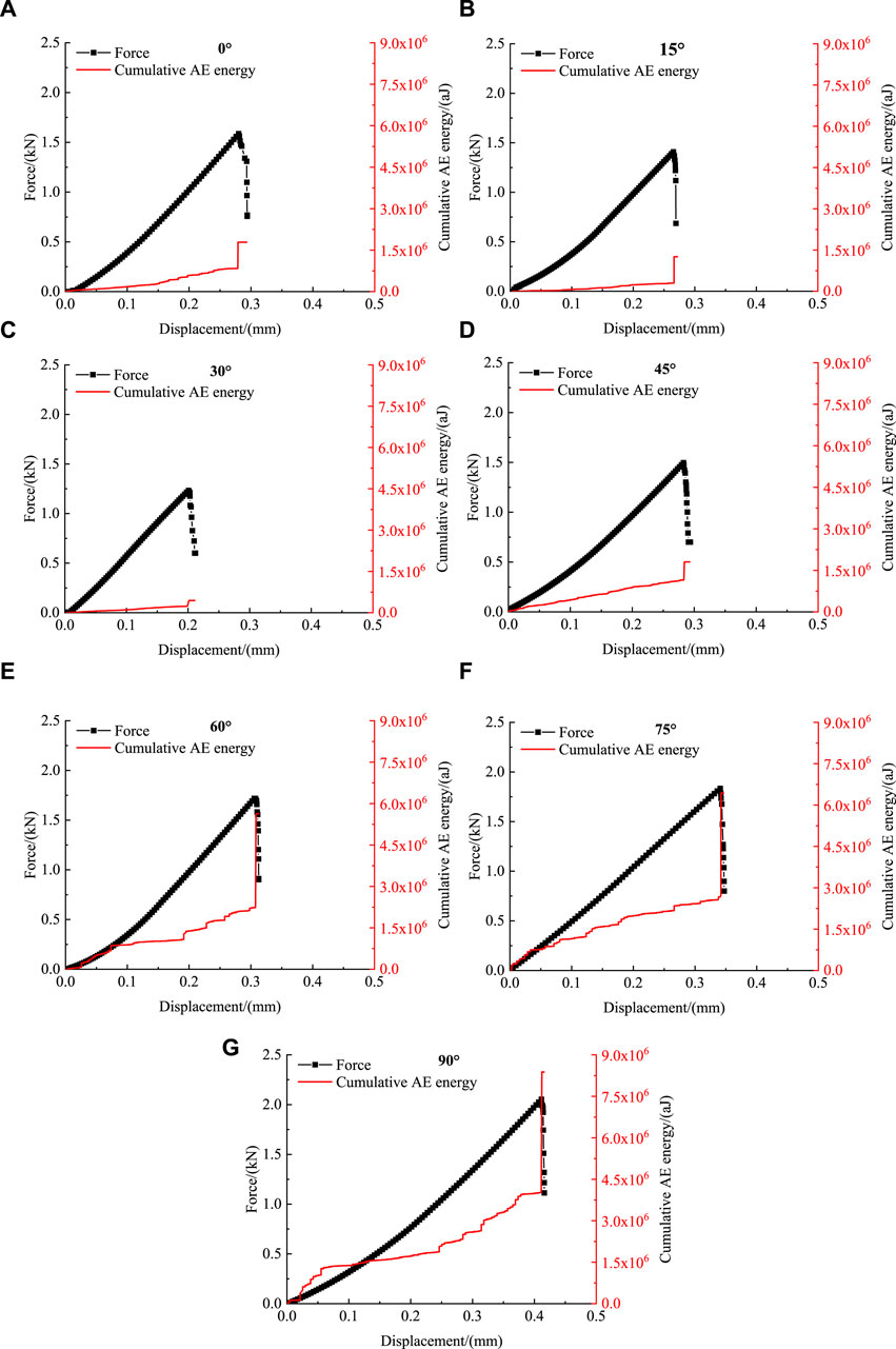
Figure 5. Association between force–displacement and cumulative AE energy–displacement in Brazilian splitting tests of coal rocks under different bedding angles. (A) α = 0°; (B) α = 15°; (C) α = 30°; (D) α = 45°; (E) α = 60°; (F) α = 75°; and (G) α = 90°.
It is generally accepted that not only the dislocations, twinning, and grain boundary movements but also the development of cracks are all results in the occurrence of AE signals. The stored elastic energy inside the specimen is released when new cracks are created or existing cracks develop further. Subject to these above actions, an elastic stress wave is generated, which propagates to the boundary of the specimen and is observed by the AE sensors (He et al., 2010). Under external loads, due to the anisotropic characteristics of coal rock specimens, the stress concentration degree and stress concentration location inside the specimens were different. This leads to differences in the initiation location, the propagation path of the crack, and the final failure pattern. Therefore, the AE signals observed also vary. However, the overall trends of the cumulative AE energy–displacement curve for the specimens with different bedding angles are similar. With increase in the displacement, the cumulative AE energy increases by several orders of magnitude. It can be divided into the following four stages: the compaction stage, the deformation stage, the crack propagation stage, and the final failure stage.
(1) In the compaction stage, with the increase in displacement, the primary microcracks were closed. In addition, there is a significant amount of AE energy generated in this stage.
(2) In the elastic deformation stage, the microcracks inside the specimens have been compacted. New cracks have not yet occurred, and coal rocks are still in the elastic stage. Therefore, the cumulative AE energy shows a quiet period in this stage.
(3) In the crack propagation stage, with further increase in displacement, new cracks occurred inside the coal rock. In addition, with the expansion and coalescence of microcracks, cumulative AE energy continues to increase.
(4) In the final failure stage, the internal cracks will further develop, fuse, and expand rapidly, and the AE energy is released dramatically. Failure occurs when the specimen reaches its tensile strength, and the cumulative AE energy reaches the ultimate value.
The cumulative AE energy for the specimens with seven different bedding angles at the final failure stage is shown in Figure 6. As illustrated, the cumulative AE energy is strongly affected by the orientation of the bedding angle. When 0° ≤ α ≤ 30°, with the increase in α, the cumulative AE energy decreases gradually. In addition, the cumulative AE energy is the least when α = 30°. When 30° ≤ α ≤ 90°, the cumulative AE energy increased gradually with the increase in α, and the cumulative AE energy reached the maximum level when α = 90°.
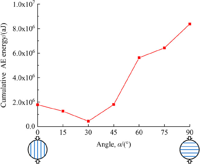
Figure 6. Association between ultimate cumulative AE energy and bedding angles.
3 Construction of the 3D numerical model
Numerical investigation can help visualize and understand the complex fracture mechanisms that are difficult to observe in physical tests. In this study, the three-dimensional Brazilian splitting numerical tests were conducted based on the CZM, which combines both advantages of the DEM and FEM. This method can simulate the whole crack evolution process of specimens under complex stress states, including nucleation, formation, and propagation of cracks for concrete-like and rock-like materials (Jiang and Meng, 2018; Trawiński et al., 2018). Cracks are generated and developed according to the actual internal stress of the specimen, and it is not defined in advance. Therefore, the crack evolution process can be simulated realistically.
3.1 Cohesive zone model
The basic theory of this model was first proposed by Dugdale (1960) and Barenblatt (1962). The constitute relation of the CZM has been comprehensively introduced in our recent study for concrete (Zhang et al., 2022) and coal rock (Xie et al., 2023). Therefore, only the core points are proposed in this study.
The core idea of this theory is to regard a crack as comprising two parts, as shown in Figure 7: one part consists of two separated free surfaces, and the other is the cohesive zone. There is a crack opening displacement Δ, which is less than a critical value
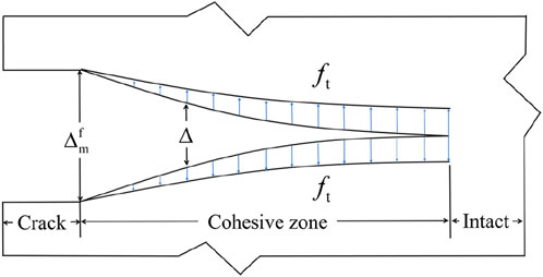
Figure 7. Schematic diagram of the cohesive zone model.
Interface elements without thickness are globally embedded in the finite element mesh by a Python script written by ourselves. Figure 8 shows an interface element embedded in two adjacent solid elements, and the constitutive relation of the interface element and solid element is independent of each other. The constitutive relations of solid elements can be linear elastic, elastoplastic, hyperelastic, and so on. In this study, the nonlinear mechanical responses, complex fracture problems, and the bedding planes of coal rock specimens are characterized by the zero-thickness interface elements (cohesive elements). The constitutive relation of these interface elements includes three stages: elastic stage, damage initiation stage, and damage evolution stage. In this numerical model, the maximum tensile stress criterion was adopted as the damage initiation criterion. If the stress state of the interface element meets the damage initiation criterion, then it will enter the damage evolution stage. When the interface element is completely damaged, it will be removed from the finite element mesh, and a microcrack is formed in the model. Once internal cracks are formed, elements in contact are rapidly identified to apply a penalty function method (ABAQUS, 2014), which calculate the normal contact force when two particles are in contact. For the general contact algorithm, the “hard” contact is employed at the interface elements along normal direction. In addition, the interface along the tangential direction is described by the classical Coulomb friction model.
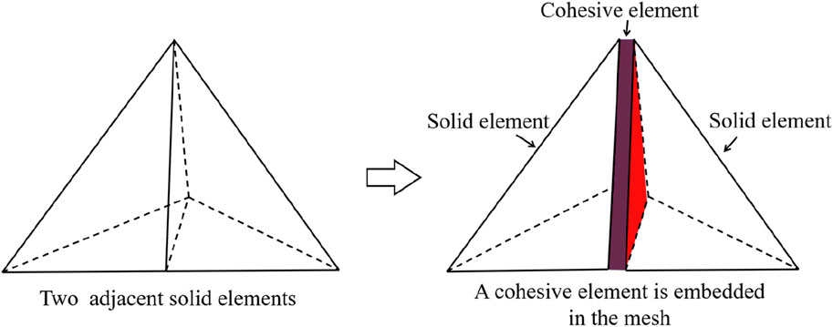
Figure 8. The cohesive element is compatible with the soil element.
3.2 Verification of the numerical model
3.2.1 Calibration of the numerical model
A 3D numerical model of Brazilian disc with a 50 mm diameter and a 25 mm thickness was established based on ABAQUS. After meshing, the interface elements (COH3D6) were embedded into the mesh by our own program written in Python. The coal matrix was simulated by tetrahedral element (C3D4), and cohesive elements (COH3D6) were used to simulate the bedding planes, as shown in Figure 9. Universal contact was set between all elements to avoid mutual penetration. At the same time, explicit dynamic and parallel solving were used to improve computational efficiency. The ABAQUS/Explicit solver is of great significance for efficiently simulating the full mechanical responses (Ren et al., 2015). The bottom loading plate was fixed. After several repeated calibrations, the top loading plate was set at a constant rate of 1 mm/s. The loading time is set as 0.5 s (Wang et al., 2015), and the time increment Δt = 10–6 (Trawiński et al., 2018), which are enough to ensure the quasi-static condition.
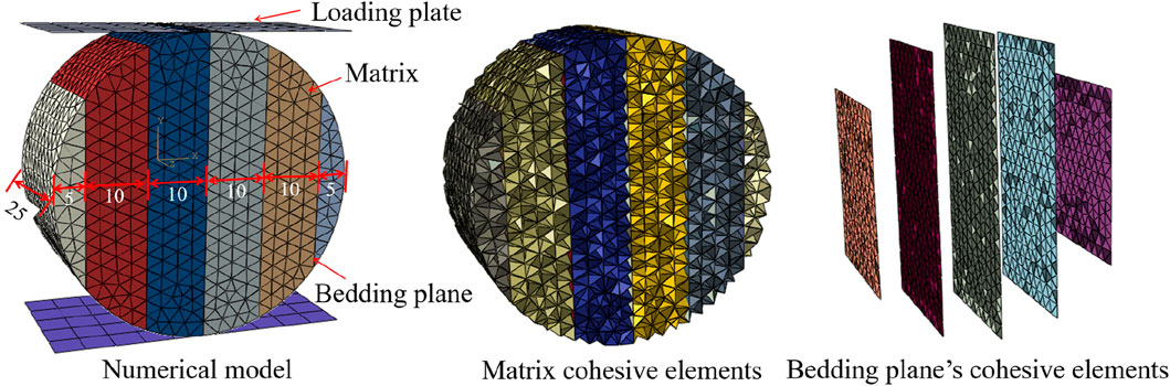
Figure 9. Numerical model of coal rock with stratified structure (mm).
It is widely accepted that the calibration of fracture parameters is highly difficult. In this study, Poisson’s ratio and elastic modulus can be easily obtained by experiments. Due to the complexity of fracture problem and limitations of the current experimental conditions, the fracture parameters of cohesive elements cannot be obtained directly through experiments. Moreover, it is extremely difficult to get the mechanical parameters of bedding planes and matrix. In order to obtain a group of suitable parameters for this numerical model, the parameters are obtained preliminarily by referring to the previous work by Jiang and Meng (2018), Xie et al. (2023), and Li et al. (2020). Then, combined with the experimental results of Brazilian splitting tests with bedding angles of 0°,45°, and 90°, the trial-and-error method was employed to calibrate the model parameters. To ensure that the failure patterns and force–displacement curves obtained by numerical analysis agree with the experimental ones, the parameters were calibrated through multiple iterations. Finally, the parameters were determined when the simulation results agree well with the experimental results. The parameters of cohesive elements are listed in Table 1.
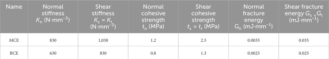
Table 1. Parameters of cohesive elements.
3.2.2 Mesh sensitivity analysis
For the simulation of Brazilian splitting tests, Jiang and Meng (2018) adopted 61,987 interface elements embedded into 32,142 solid elements to predict the mechanical response and failure mode of isotropic rock specimens. In this study, both the coal matrix and bedding planes are considered in this 3D numerical model. Therefore, the mesh sensitivity analyzed is an indispensable part of this simulation. In this study, three different mesh sizes (Le = 1.5 mm, 2.0 mm, and 2.5 mm) have been designed. In addition, for each mesh size, the specimens have three different inclination angles (α = 0°, 45°, and 90°). The element numbers for the specimens with different element sizes are presented in Table 2. The force–displacement curves and the failure process of the Brazilian disc tests for numerical models with different mesh sizes (Le = 1.5 mm, 2.0 mm, and 2.5 mm) and different bedding angles (α = 0°, 45°, and 90°) are, respectively, plotted in Figure 10 and Figure 11.
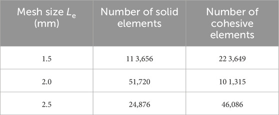
Table 2. Number of elements for different mesh sizes.
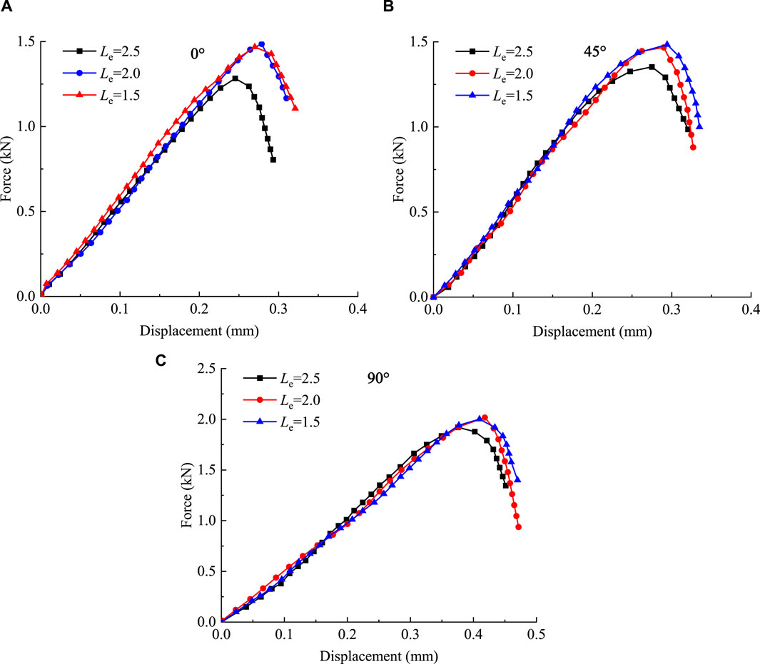
Figure 10. Mesh sensitivity analysis of the force–displacement responses. (A) α = 0°; (B) α = 45°; and (C) α = 90°.
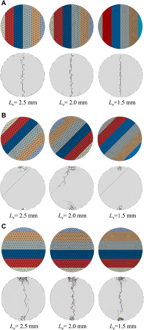
Figure 11. Mesh sensitivity analysis of the failure modes. (A) α = 0°; (B) α = 45°; and (C) α = 90°.
The damage evolution and crack development of numerical models are illustrated by cohesive elements, and the increase in the element number causes the model to have more uniform damage and cracks. Therefore, the model with a higher mesh precision can better reflect the real damage condition and fracture pattern. Comparing the simulation results, it can be seen from Figure 10 that the numerical model with coarse mesh size (Le = 2.5 mm) may underestimate the tensile strength of the model. However, the failure patterns can be well-predicted by the three numerical models with different mesh sizes. The calculation times of each specimen with different mesh sizes (Le = 1.5 mm, 2.0 mm, and 2.5 mm) are approximately 3 h, 8 h, and 12 h, respectively. To balance the accuracy and calculation time, we assumed that the mesh size (Le = 2.0 mm) is enough to simulate the coal specimens with different bedding angles, and it is also applied to the following numerical study.
4 Numerical study
4.1 Simulation results
The numerical analysis for the coal rock models with seven different bedding angles is conducted. The fracture behavior of the numerical models compared with the final failure pattern of the experimental results is presented in Figure 12. Accordingly, the number of cohesive elements removed from the numerical model could characterize the fracture behavior of the numerical model to some degree. By monitoring the number of cohesive cracks formed in the numerical models, the displacement–cumulative crack number curves for the specimens are plotted in Figure 13, and the axial force–displacement curves obtained by experiments and simulations are also plotted in Figure 13. Figure 14 shows the tensile strength of coal rock as determined by both experimental and simulation methods under Brazilian splitting tests.
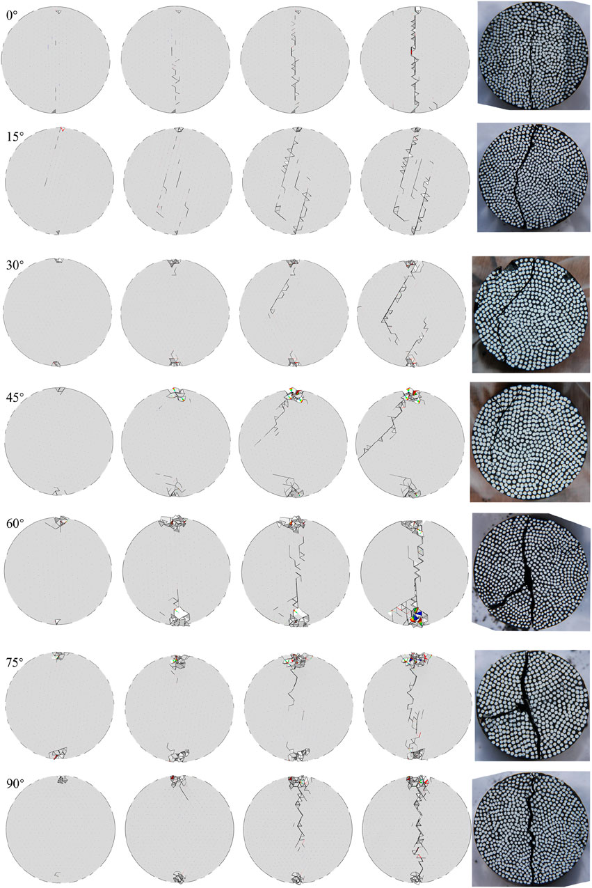
Figure 12. Crack initiation and propagation of numerical models and the failure modes of the tests at seven bedding angles.
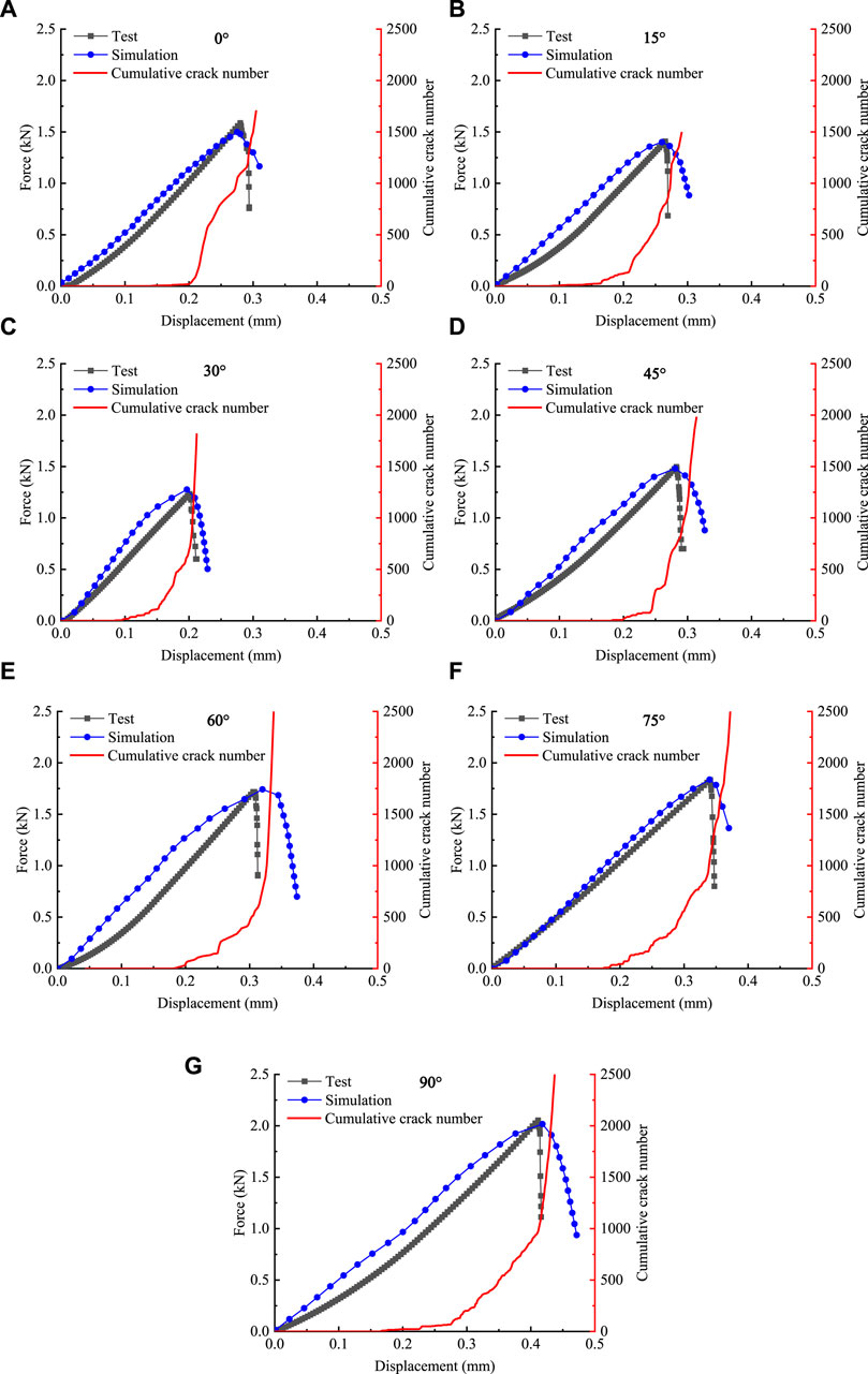
Figure 13. Comparisons between experiments and simulations at seven bedding angles. (A) α =0°; (B) α =15°; (C) α =30°; (D) α =45°; (E) α =60°; (F) α =75°; and (G) α =90°.
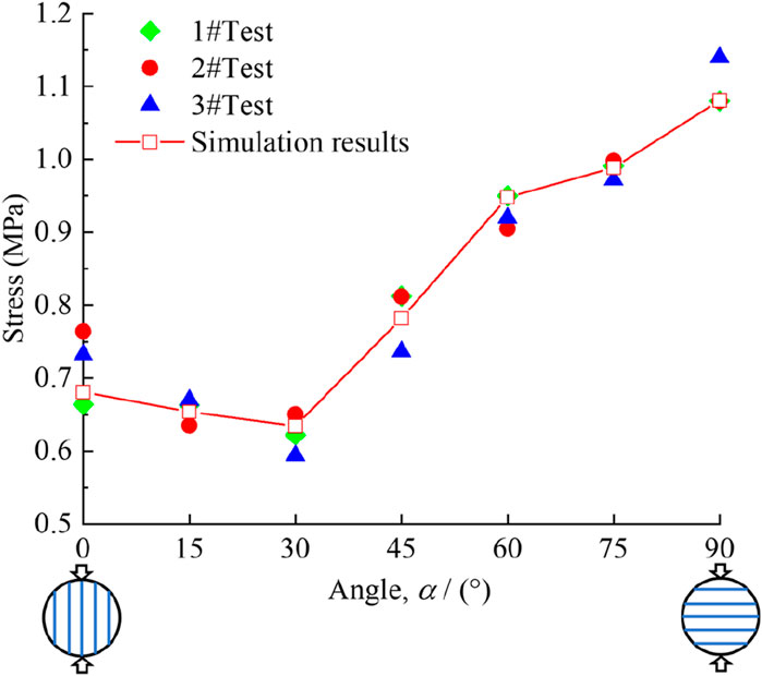
Figure 14. Comparisons of the tensile strength by experiments and simulations.
As illustrated in these figures, the final fracture patterns of the numerical model with seven different bedding angles are in good agreement with the experimental results. In addition, the simulations based on the CZM can effectively predict the whole failure process and mechanical responses of coal rock specimens under complex stress state. The discrepancies between numerical simulations and experimental results can be attributed to the following reasons: on one hand, the coal rock specimens contain a large number of tiny pores and defects, which are not considered in the numerical model. On the other hand, the bedding planes in the coal rock are not flat and are not evenly spaced. To simplify the calculations, the bedding planes are simplified as evenly spaced flat planes in the numerical model, which can lead to certain errors. However, overall, the numerical model is able to capture the essence of this problem and effectively simulate the bedding effects of the coal rock.
As we all know, coal rock is a typical quasi-brittle material. There are many microcracks inside the coal rock specimens, and under external loads, stress concentration always occurs at the tip of the microcrack, and then microcracks begin to propagate and penetrate, and finally, the specimen gets destroyed. According to crack morphology, the specimens can be roughly divided into the following three categories:
(1) Tensile splitting failure along the bedding planes. When α ≤ 45°, the main crack propagates mainly along bedding planes. Due to the great difference between bedding planes and coal matrix, stress concentration occurs at the interface, and cracks are also initiated at the interface. As the displacement further increases, the cracks propagate further and finally form the main cracks through the whole specimen. In this case, it is mainly the cohesion between the bedding planes that resists the tensile stress. In addition, when the stress reaches the cohesion strength, the specimens present the tensile failure pattern along the bedding planes.
(2) Shear and tensile mixed failure along matrix and bedding planes. When α = 60° or 75°, the main crack passes through both the matrix and the bedding planes, and it presents a circular arc. Moreover, secondary cracks occur along the bedding planes. Under external loads, when the shear force on the bedding plane exceeds the shear strength, the crack occurs along the bedding planes. On the one hand, the compressive stress will restrain the sliding shear failure along the bedding plane, and on the other hand, due to the Poisson effect, the crack will propagate through the bedding plane and matrix.
(3) Tensile splitting failure along the matrix. When the bedding angle is 90°, the major crack cuts the bedding plane vertically and propagates through the matrix. With the increase in the loads, cracks propagate through the matrix perpendicular to the bedding planes. Finally, the major crack path is formed along the loading direction, and the major crack is serrated.
In addition, it can be observed from the displacement–cumulative crack number curves that the specimens with different bedding angles subjected to Brazilian tensile tests have the following characteristics:
(1) Although the specific trend for each curve varies, the overall trend of the curves can still be roughly classified into four stages: the elastic stage, the crack initiation stage, the crack rapid expansion stage, and the final failure stage.
(2) At the initial loading stage, the specimens are in the elastic stage and there are no cracks in the models. As the displacement increases, some of the cohesive elements satisfy the failure criterion and are then deleted from the finite element mesh, implying that crack formation will gradually initiate. With the further increase in displacement, an increasing number of cohesive elements are removed from the model, resulting in the development of cracks. During the crack rapid expansion stage, the crack growth rate gradually increases. As the main crack penetrates the specimen, there is a turning point in the displacement–cumulative crack number curve. Moreover, the specimen reaches its ultimate tensile strength.
4.2 Failure mechanism analysis
For the Brazilian disc with any inclination angle, the stress at the mid-point can be decomposed into a shear stress along the bedding plane and a normal stress perpendicular to the bedding plane direction, as described in Figure 15. In addition, σn is the normal stress perpendicular to the bedding plane, τ is the shear stress parallel to the bedding plane, and σp is the compressive stress at the center point.
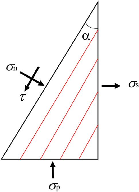
Figure 15. Stress component (Wang et al., 2020).
When α = 0°, there is no shear stress and only normal tensile stress on the bedding plane. It is obvious that the normal tensile stress leads to failure along the bedding plane. In addition, when α = 90°, there is only normal compression stress and no shear stress on the bedding planes. The specimens show a tensile failure when the tensile stress is equal to the tensile strength of the coal matrix. The strength for the bedding planes is generally lower than that of the matrix. Consequently, the tensile strength of the coal rock specimen (α = 0°) is lower than that of the specimen (α = 90°).
The inclination angle is within the range of 15° ≤ α ≤ 75°. Both the normal stress and shear stress are obviously changed with the variation in the bedding angle, and the failure patterns become more complex. By analyzing the tensile strength and failure modes of the specimens, it can be seen that the shear action is significant when the inclination angle is in the range of 15° ≤ α ≤ 45°. Consequently, subjected to the combined actions of normal tensile stress and shear stress, the tensile strength is small and the main crack propagates along the bedding plane. Additionally, with the increase in the inclination angle, the normal stress perpendicular to the bedding planes begins to restrain the tensile failure and shear slip. Thus, the tensile strength of the specimen increases with increase in the bedding angle from 30° to 75°. In addition, due to the Poisson effect, the crack will propagate through the bedding plane and matrix.
5 Conclusion
In this paper, both the experimental and numerical Brazilian splitting tests were conducted for investigating the effect of bedding angles. The mechanical behaviors, fracture process, and AE characteristics were all investigated. Moreover, the corresponding 3D numerical simulations were performed based on the continuous–discontinuous simulation method on the platform of ABAQUS/Explicit. Through comparative analyses, this study concludes that
(1) The bedding angle has a great effect on the tensile strength of the coal rock. As bedding angle increases from 0° to 90°, the tensile strength first decreases (0° ≤ α ≤ 30°) and then increases gradually (30° ≤ α ≤ 90°). When α = 30°, the tensile strength reaches the minimum, and when α = 90°, it is the maximum.
(2) The final failure pattern is also greatly influenced by the bedding angle. When α ≤ 45°, the coal rock specimens are mainly destroyed along bedding planes, and the main crack deviates from the center of the disc, except α = 0°. When the bedding angle is in the range of 60° ≤ α ≤ 90°, the main crack passes through the center of the disc; moreover, the secondary cracks may also develop along the bedding planes.
(3) The cumulative AE energy–displacement curves for the coal rock across seven different bedding angles show similar evolutionary trends. The evolution process of cumulative AE energy can be classified into four stages: initial compaction stage, elastic deformation stage, crack propagation stage, and destruction stage. As the bedding angle increases from 0° to 90°, the tensile strength decreases initially (0° ≤ α ≤ 30°) and then gradually increases (30° ≤ α ≤ 90°).
(4) The simulation results demonstrate strong concordance with the experimental results, indicating that the numerical analysis method based on CZM is effective in predicting the non-linear mechanical responses, overall failure process, and fracture behavior of coal rocks under complex stress states. As a result, the 3D numerical model could be applied in the simulation of rock engineering with bedding effects.
Data availability statement
The original contributions presented in the study are included in the article/Supplementary Material; further inquiries can be directed to the corresponding author.
Author contributions
JH: data curation, visualization, and writing–original draft. LZ: formal analysis, methodology, and writing–review and editing. MH: funding acquisition, project administration, supervision, and writing–review and editing.
Funding
The author(s) declare that financial support was received for the research, authorship, and/or publication of this article. This work was supported by the Foundation of State Key Laboratory for Geomechanics and Deep Underground Engineering, China University of Mining and Technology, Beijing (Grant no. SKLGDUEK 2217) and by Collaborative Innovation Center for Prevention and Control of Mountain Geological Hazards of Zhejiang Province (Grant no. PCMGH-2022-03).
Conflict of interest
The authors declare that the research was conducted in the absence of any commercial or financial relationships that could be construed as a potential conflict of interest.
Publisher’s note
All claims expressed in this article are solely those of the authors and do not necessarily represent those of their affiliated organizations, or those of the publisher, the editors, and the reviewers. Any product that may be evaluated in this article, or claim that may be made by its manufacturer, is not guaranteed or endorsed by the publisher.
References
Barenblatt, G. I. The mathematical theory of equilibrium cracks in brittle fracture. , 1962;7:55–129. doi:10.1016/s0065-2156(08)70121-2
Brown, E. T., Green, S. J., and Sinha, K. P. (1981). The influence of rock anisotropy on hole deviation in rotary drilling — a review. Int. J. Rock Mech. Min. Sci. Geomechanics Abstr. 18 (5), 387–401. doi:10.1016/0148-9062(81)90003-6
Cho, J. W., Kim, H. N., Jeon, S. K., and Min, K. B. (2012). Deformation and strength anisotropy of Asan gneiss, Boryeong shale, and Yeoncheon schist. Int. J. Rock Mech. Min. Sci. 50, 158–169. doi:10.1016/j.ijrmms.2011.12.004
Claesson, J., and Bohloli, B. (2002). Brazilian test: stress field and tensile strength of anisotropic rocks using an analytical solution. Int. J. Rock Mech. Min. Sci. 39, 991–1004. doi:10.1016/s1365-1609(02)00099-0
Dugdale, D. S. (1960). Yielding of steel sheets containing slits. Pergamon 8 (2), 100–104. doi:10.1016/0022-5096(60)90013-2
Gao, Q., Tao, J. L., Hu, J. Y., and Yu, X. B. (2015). Laboratory study on the mechanical behaviors of an anisotropic shale rock. J. Rock Mech. Geotechnical Eng. 7 (2), 213–219. doi:10.1016/j.jrmge.2015.03.003
Guo, W. Y., Gu, Q. Y., Tan, Y. L., and Hu, S. (2019). Case studies of rock bursts in tectonic areas with facies change. Energies 12 (7), 1330. doi:10.3390/en12071330
Hatzor, Y. H., Feng, X. T., Li, S. J., Yagoda-Biran, G., Jiang, Q., and Hu, L. (2015). Tunnel reinforcement in columnar jointed basalts: the role of rock mass anisotropy. Tunn. Undergr. Space Technol. 46, 1–11. doi:10.1016/j.tust.2014.10.008
He, M. C., Miao, J. L., and Feng, J. L. (2010). Rock burst process of limestone and its acoustic emission characteristics under true-triaxial unloading conditions. Int. J. Rock Mech. Min. Sci. 47 (2), 286–298. doi:10.1016/j.ijrmms.2009.09.003
Heng, S., Guo, Y. T., Yang, C. H., Daemen, J. J., and Li, Z. (2015b). Experimental and theoretical study of the anisotropic properties of shale. Int. J. Rock Mech. Min. Sci. 74, 58–68. doi:10.1016/j.ijrmms.2015.01.003
Heng, S., Yang, C. H., Zhang, B. P., et al. (2015a). Experimental research on anisotropic properties of shale. Rock Soil Mech. 36 (3), 609–616. doi:10.16285/j.rsm.2015.03.001
Jiang, H. X., and Meng, D. G. (2018). 3D numerical modelling of rock fracture with a hybrid finite and cohesive element method. Eng. Fract. Mech. 199, 280–293. doi:10.1016/j.engfracmech.2018.05.037
Laboratory Tests (1977). Suggested methods for determining tensile strength of rock materials. The Society.
Li, E. Q., Zhang, H. C., Zhang, L. F., et al. (2020). Investigation on Brazilian tests and simulations of carbonaceous slate with different bedding angles. Rock Soil Mech. 41 (9), 2869–2879.
Nguyen, T. S., and Le, A. D. (2015). Development of a constitutive model for a bedded argillaceous rock from triaxial and true triaxial tests. Can. Geotechnical J. 52 (8), 1072–1086. doi:10.1139/cgj-2013-0323
Park, B., Min, K. B., Thompson, N., and Horsrud, P. (2018). Three-dimensional bonded-particle discrete element modeling of mechanical behavior of transversely isotropic rock. Int. J. Rock Mech. Min. Sci. 110, 120–132. doi:10.1016/j.ijrmms.2018.07.018
Peng, J., Wong, L. N. Y., and Teh, C. I. (2021). Influence of grain size on strength of polymineralic crystalline rock: new insights from DEM grain-based modeling. J. Rock Mech. Geotechnical Eng. 13 (4), 755–766. doi:10.1016/j.jrmge.2021.01.011
Qin, Z., Fu, H. L., and Chen, X. X. (2019). A study on altered granite meso-damage mechanisms due to water invasion-water loss cycles. Environ. Earth Sci. 78 (14), 428. doi:10.1007/s12665-019-8426-6
Ren, F. Q., Zhu, C., and He, M. C. (2019). Moment tensor analysis of acoustic emissions for cracking mechanisms during schist strain burst. Rock Mech. Rock Eng. 53 (1), 153–170. doi:10.1007/s00603-019-01897-3
Ren, W. Y., Yang, Z. J., Sharma, R., Zhang, C., and Withers, P. J. (2015). Two-dimensional X-ray CT image based meso-scale fracture modelling of concrete. Eng. Fract. Mech. 133, 24–39. doi:10.1016/j.engfracmech.2014.10.016
Rocco, C., Guinea, G. V., Planas, J., and Elices, M. (2001). Review of the splitting-test standards from a fracture mechanics point of view. Cem. Concr. Res. 31 (1), 73–82. doi:10.1016/s0008-8846(00)00425-7
Skoczylas, N., and Wierzbicki, M. (2014). Evaluation and management of the gas and rock outburst hazard in the light of international legal regulations. Archives Min. Sci. 59 (4), 1119–1129. doi:10.2478/amsc-2014-0078
Suo, Y., Chen, Z., Rahman, S. S., and Song, H. (2020). Experimental and numerical investigation of the effect of bedding layer orientation on fracture toughness of shale rocks. Rock Mech. Rock Eng. 53 (8), 3625–3635. doi:10.1007/s00603-020-02131-1
Tan, Y. L., Pan, Z. J., Liu, J. S., Wu, Y., Haque, A., and Connell, L. D. (2017). Experimental study of permeability and its anisotropy for shale fracture supported with proppant. J. Nat. Gas Sci. Eng. 44, 250–264. doi:10.1016/j.jngse.2017.04.020
Tavallali, A., and Vervoort, A. (2010a). Effect of layer orientation on the failure of layered sandstone under Brazilian test conditions. Int. J. Rock Mech. Min. Sci. 47 (2), 313–322. doi:10.1016/j.ijrmms.2010.01.001
Tavallali, A., and Vervoort, A. (2010b). Failure of layered sandstone under Brazilian test conditions: effect of micro-scale parameters on macro-scale behaviour. Rock Mech. Rock Eng. 43 (5), 641–653. doi:10.1007/s00603-010-0084-7
Trawiński, W., Tejchman, J., and Bobiński, J. (2018). A three-dimensional meso-scale modelling of concrete fracture, based on cohesive elements and X-ray μCT images. Eng. Fract. Mech. 189, 27–50. doi:10.1016/j.engfracmech.2017.10.003
Wang, H., Ren, F. Q., and Chang, Y. (2020). Effect of bedding angle on tunnel slate failure behavior under indirect tension. Geomatics, Nat. Hazards Risk 11 (1), 428–445. doi:10.1080/19475705.2020.1729870
Wang, J., Li, S. C., Li, L. P., Lin, P., Xu, Z. h., and Gao, C. l. (2017). Attribute recognition model for risk assessment of water inrush. Bull. Eng. Geol. Environ. 78 (2), 1057–1071. doi:10.1007/s10064-017-1159-4
Wang, X. F., Yang, Z. J., Yates, J. R., Jivkov, A., and Zhang, C. (2015). Monte Carlo simulations of mesoscale fracture modelling of concrete with random aggregates and pores. Constr. Build. Mater. 75, 35–45. doi:10.1016/j.conbuildmat.2014.09.069
Wu, J., Jing, H., Gao, Y., Meng, Q., Yin, Q., and Du, Y. (2022). Effects of carbon nanotube dosage and aggregate size distribution on mechanical property and microstructure of cemented rockfill. Cem. Concr. Compos. 127, 104408. doi:10.1016/j.cemconcomp.2022.104408
Wu, J., Jing, H., Yin, Q., Yu, L., Meng, B., and Li, S. (2020). Strength prediction model considering material, ultrasonic and stress of cemented waste rock backfill for recycling gangue. J. Clean. Prod. 276, 123189. doi:10.1016/j.jclepro.2020.123189
Wu, J., Wong, H. S., Zhang, H., Yin, Q., Jing, H., and Ma, D. (2024). Improvement of cemented rockfill by premixing low-alkalinity activator and fly ash for recycling gangue and partially replacing cement. Cem. Concr. Compos. 145, 105345. doi:10.1016/j.cemconcomp.2023.105345
Wu, P. F., Liang, W. G., Li, Z. G., Cao, M. T., and Yang, J. F. (2016). Investigations on mechanical properties and crack propagation characteristics of coal and sandy mudstone using three experimental methods. Rock Mech. Rock Eng. 50 (1), 215–223. doi:10.1007/s00603-016-1048-3
Xie, H., Zhang, L., Sun, X., Wang, X., and Cao, Y. (2023). Tensile failure characteristics of coal and its 3D cohesive zone model. Geotechnical Geol. Eng. 41, 2299–2312. doi:10.1007/s10706-023-02398-5
Xu, G. W., He, C., and Wang, X. (2019). Mechanical behavior of transversely isotropic rocks under uniaxial compression governed by micro-structure and micro-parameters. Bull. Eng. Geol. Environ. 79 (4), 1979–2004. doi:10.1007/s10064-019-01690-0
Zhang, J. C. (2013). Borehole stability analysis accounting for anisotropies in drilling to weak bedding planes. Int. J. Rock Mech. Min. Sci. 60, 160–170. doi:10.1016/j.ijrmms.2012.12.025
Zhang, L., Xie, H., and Feng, J. (2022). Mesoscale modeling and failure mechanism of concrete considering pore structures and actual aggregate shapes. Constr. Build. Mater. 353, 129133. doi:10.1016/j.conbuildmat.2022.129133
Zhang, S. C., Li, Y. Y., Shen, B. T., Sun, X., and Gao, L. (2019). Effective evaluation of pressure relief drilling for reducing rock bursts and its application in underground coal mines. Int. J. Rock Mech. Min. Sci. 114, 7–16. doi:10.1016/j.ijrmms.2018.12.010
Keywords: coal rock, bedding effect, Brazilian splitting test, acoustic emission, continuous–discontinuous, cohesive zone model
Citation: Hu J, Zhang L and He M (2024) Investigation of the bedding effect on coal rock under Brazilian splitting tests. Front. Earth Sci. 12:1416035. doi: 10.3389/feart.2024.1416035
Received: 23 April 2024; Accepted: 04 June 2024;
Published: 25 June 2024.
Edited by:
Jiangyu Wu, China University of Mining and Technology, ChinaReviewed by:
Tao Ni, Chengdu University of Technology, ChinaYuhao Wang, Luoyang Institute of Science and Technology, China
Copyright © 2024 Hu, Zhang and He. This is an open-access article distributed under the terms of the Creative Commons Attribution License (CC BY). The use, distribution or reproduction in other forums is permitted, provided the original author(s) and the copyright owner(s) are credited and that the original publication in this journal is cited, in accordance with accepted academic practice. No use, distribution or reproduction is permitted which does not comply with these terms.
*Correspondence: Longfei Zhang, bG9uZ2ZlaTk1MDEwNEAxNjMuY29t