 Binwei Xia
 Xingguo Zhang
 Zikun Ma
 Xinqin Xu
- State Key Laboratory of Coal Mine Disaster Dynamics and Control, Chongqing University, Chongqing, China
Multi-stage fracturing in Horizontal well increases the permeability of coalbed methane by generating multiple fractures. However, the heterogeneity of coal reservoirs is a crucial factor that cannot be ignored in the study of multiple hydraulic fracture propagation. Therefore, we established a two-dimensional model for multiple hydraulic fracture propagation based on the combined finite-discrete element method (FDEM) and assigned a Weibull distribution function to the heterogeneity of the physical parameters of the cohesive elements in the model. The objective was to simulate and study the fracture propagation law of multi-cluster fracturing in horizontal wells in heterogeneous coal reservoirs. The research results indicated that: 1) as the heterogeneity of the coal reservoir weakened, the deflection angle of the main fracture increased. More secondary fractures were generated in the coal reservoir, leading to significant discontinuity. 2) The fracturing disturbance area was always concentrated at the tip of the main fracture, with a double wing shape. However, the fracturing disturbance areas at the tips of multiple main fractures could easily converge, with a square shape; 3) It is recommended to use a moderate injection rate and increase the perforation spacing appropriately when hydraulic fracturing is carried out in coal reservoirs with a heterogeneity coefficient m=5.
1 Introduction
Coalbed methane is a clean and efficient fossil energy source with broad development prospects. At present, multi-stage fracturing in horizontal wells has become an effective means of extracting coalbed methane. The multiple hydraulic fractures formed by it can effectively improve the permeability of coal reservoirs. However, coal reservoirs have strong heterogeneity, which has a huge impact on the expansion of multiple hydraulic fractures (Parvizi and Rezaei-Gomari, 2017; Tang and Li, 2018; Dou and Wang, 2022). The impact of coal reservoir heterogeneity on multiple hydraulic fracture propagation is not yet clear, so studying this problem is of great significance.
In recent decades, many scholars have conducted extensive experimental research on hydraulic fracturing (Li Y. et al., 2018; Zhou and Zeng, 2018; Akpanbayeva and Issabek, 2023; Luo and Gao, 2023). Although experimental method plays an invaluable role in studying this field, it still has certain limitations, such as small sample sizes and difficulty in effectively observing the dynamic propagation process of fractures during the experimental process. Hence, numerical simulation method that can overcome these shortcomings has become very popular in this field.
In the past few decades, a number of numerical simulation methods have been developed to simulate multiple hydraulic fracture propagation. Traditional finite element method (FEM) (Wangen, 2011; Wei and Kao, 2021), extended finite element method (XFEM) (Li X. et al., 2018; Liao and Hu, 2022), discrete element method (DEM) (Duan and Li, 2020; Yang and Geng, 2020), phase field method (PFM) (Ehlers and Luo, 2017; Ni and Zhang, 2020), and combined finite-discrete element method (FDEM) (Carrier and Granet, 2012; Sun and Zheng, 2020) are one of the most important methods. The initial FEM was based on the assumption of homogeneity, so it was generally utilized to simulate hydraulic fracture propagation in homogeneous reservoirs. It was not sufficient to simulate heterogeneous characteristics such as multiphase, porous, and natural fractures of reservoir rocks. Therefore, to simulate the discontinuous characteristics of rocks, numerical methods based on the theory of discontinuous media have been proposed, including the cohesive zone method (CZM), FDEM, XFEM, and DEM, etc. The core idea of these methods is to characterize fractures through dimensionality reduction, such as cohesive elements in FDEM and reinforcement functions in XFEM. Among them, FDEM is employed to simulate the random fracture propagation and the arbitrary flow of fluids in fractures by inserting cohesive elements between matrix elements. Compared with other numerical methods, FDEM has the advantage of being able to simulate the formation of complex fracture networks under heterogeneous reservoir conditions, providing a powerful means for studying multiple hydraulic fracture propagation in heterogeneous coal reservoirs (Guo and Zhao, 2015; Sun and Zheng, 2020).
However, few studies have considered the impact of coal reservoir heterogeneity on multiple hydraulic fracture propagation. Therefore, to explore the influence of coal reservoir heterogeneity on the simultaneous expansion of multiple fractures, we employed FDEM by embedding cohesive elements globally between solid matrix elements to simulate multiple hydraulic fracture propagation. The physical parameters of cohesive elements were heterogenized using the Weibull distribution function. On this basis, numerical simulations of multiple hydraulic fracture propagation were performed under different heterogeneity coefficient to explore the influence of coal reservoir heterogeneity on fracture morphology and pressure curve. Then the effects of injection rates and perforation spacing on fracture morphology, fracture pressure, and fracturing disturbance area were investigated in a coal reservoir with a fixed heterogeneity coefficient. Our research goal was to provide theoretical support and design guidance for multiple hydraulic fracture propagation under complex geological conditions.
2 Methods
The basic idea of FDEM is to embed cohesive elements between the divided matrix elements (Figure 1). The coupling of the two types of elements can simulate the deformation of the continuum. The solid matrix element is utilized to simulate porous media, while the cohesive element is used to simulate elastic-plastic fracture. The propagation of fractures is considered as the failure of the cohesive element. At the same time, the cohesive element with a degree of freedom of pore pressure not only can simulate the tangential and normal flows of fluid within the element but also the transformation of different flow states before and after the fracturing of the element, making it suitable for simulating the fluid flow of hydraulic fractures.
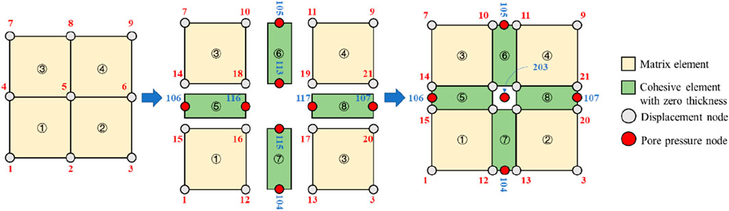
Figure 1. The schematic diagram of the idea of inserting cohesive elements in FDEM.
2.1 Equilibrium equations of coal matrix
In the simulation, the reservoir is assumed to be a porous medium. Only a single phase of fluid is saturated into the solid skeleton and pores. The total stress within the reservoir consists of two parts: the total effective stress
Where
During the hydraulic fracturing process, the coal reservoir is always in a saturated state. In a saturated state, the fluid in the porous medium should comply with the continuity equation. The total mass change rate of the fluid in the control body is equal to the mass of the fluid passing through the surface of the control body per unit time (Sun and Zheng, 2020), and the specific equation is as follows:
where J represents the rate of volume change of the porous medium; ρw, nw, and vw stand for the fluid mass density, medium porosity, and the average velocity of the liquid relative to the solid phase, respectively; χ is a space vector.
2.2 Cohesive element liquid flow equation
Figure 2 shows that the flow of fracturing fluid inside the fracture is composed of tangential flow inside the fracture and normal filtration flow on the fracture surface. The fracturing fluid is assumed to be an incompressible Newtonian fluid. The tangential flow equation within the fracture (Carrier and Granet, 2012) is as follows:
where q represents the volumetric flow velocity passing through the cross-section of the fracture, w stands for the width of the fracture, μ denotes the viscosity of the fracturing fluid, and
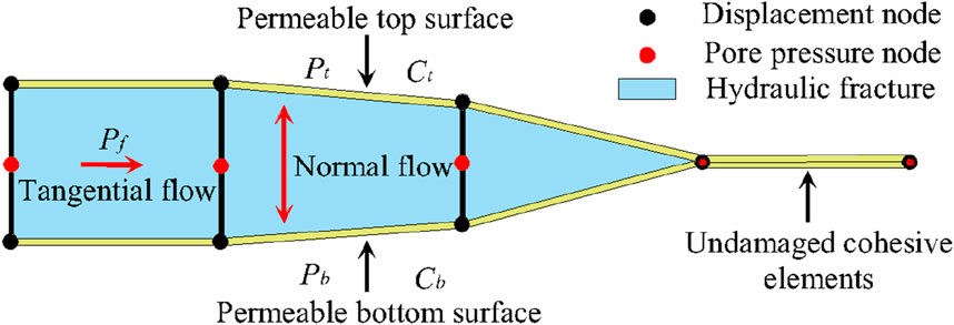
Figure 2. The schematic diagram of hydraulic fracture simulation using the cohesive element.
The definition of normal flow representing the filtration behavior from fractures to porous coal matrix (Guo and Zhao, 2015) is as follows:
where qt and qb indicate the normal flow rates at the top and bottom of the cohesive element, respectively, ct and cb symbolize the filtration coefficients of the top and bottom surfaces of the cohesive element, respectively, pf signifies the fracture flow pressure in the cohesive element, and pt and pb are the pore pressures at the top and bottom surfaces of the cohesive element, respectively.
2.3 Cohesive element separation law
In the construction of the traction separation constitutive model of the cohesive element, we used the quadratic nominal stress criterion (Sun and Zheng, 2020) as the initial damage criterion of the element. When the element stress state satisfies the following functional equation, the element stress state reaches its extreme strength value and initial damage begins to occur:
where ⟨σs⟩ is the normal stress of the cohesive element; σs and σt are the shear stress in two orthogonal directions along the plane in a three-dimensional state; Nmax is the ultimate tensile strength of the cohesive element; Smax and Tmax are the ultimate shear strength of the cohesive element in two orthogonal directions, respectively.
By introducing the damage variable D to describe the evolution process of element damage, the actual stress state of the cohesive element at a certain instant is defined as follows:
where D stands for the damage variable, and D=1 means that the cohesive element completely fails (i.e., fracture propagation occurs);
where δm represents the effective displacement, ⟨δn⟩ signifies the normal displacement; δs and δt symbolize the tangential displacement in two orthogonal directions.
The constitutive curve of the effective traction force of the cohesive element as a function of effective displacement is shown in Figure 3, where E represents the element stiffness related to geometric parameters;
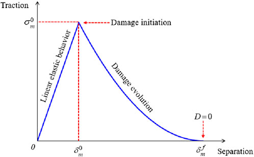
Figure 3. The constitutive model of the cohesive element.
The mixed fracture energy Gc varies with the different mixing ratios of type I and type II fracture forms. We adopted a mixed fracture energy model based on the B-K criterion (Sun and Zheng, 2020), and the formula is as follows:
where
2.4 Model validation
Given that the reliability of FDEM in simulating single hydraulic fracture propagation has been proven by many scholars (Carrier and Granet, 2012; Sun and Zheng, 2020), the reliability of single-fracture model will not be discussed here. In this study, we focused on verifying the modeling effectiveness of multiple hydraulic fracture propagation.
The propagation direction of multiple hydraulic fractures was compared with Wu’s numerical solutions (Wu and Olson, 2015). According to Wu’s case, a 100 m × 111 m model was established with two horizontal perforations spaced at 10 m intervals. The Young’s modulus of the reservoir is 30 GPa, the Poisson’s ratio is 0.35, the maximum and minimum horizontal stresses are both 46.78 MPa, and the minimum principal stress direction is in the x-direction. The viscosity of the fracturing fluid is 0.001 Pa·s, and the water injection rate is 0.0018 m3/s. According to Wu’s description, we have established the model shown in Figure 4. In addition to the parameters mentioned above, it is also necessary to provide the parameters of the cohesive elements, as shown in Table 1. Finally, a two-dimensional homogeneous reservoir model was established, consisting of 16320 matrix elements and 33000 cohesive elements.
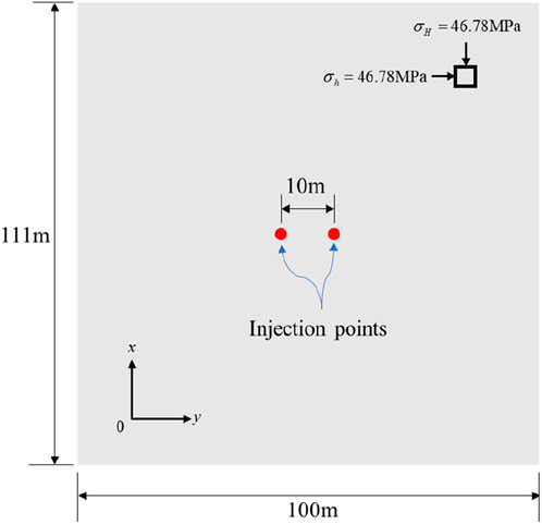
Figure 4. The schematic diagram of the validation model.

Table 1. The parameters of cohesive elements in the validation model.
Figure 5 exhibits that the numerical results of fracture propagation simulated in our study are in good agreement with the numerical calculation results of Wu. The expansion of two fractures tends to move away from each other, which may be attributed to the strong stress interference under a low-stress difference. Meanwhile, we found that the two hydraulic fractures in our model are not completely symmetrical. This is because the cohesive elements in the FDEM are inserted between the matrix elements, resulting in a certain dependence of the propagation direction of hydraulic fractures on element meshing.
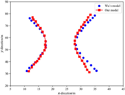
Figure 5. Comparison between our simulation results and Wu’s numerical solution in the model validation process.
3 Model settings
3.1 Cohesive strength heterogeneity based on weibull distribution function
In rock mechanics, the Weibull distribution function is widely employed to characterize the heterogeneity of rock (Lei and Gao, 2018; Li and Guo, 2020). The density function expression of the Weibull distribution is as follows:
where ϕ(x) represents the probability density where the strength of the coherent element is equal to x; a stands for the statistical average of material strength; m denotes the heterogeneity coefficient, with a value range of (0, ∞). However, it is worth mentioning that a smaller m represents a stronger degree of heterogeneity in the coal reservoir and vice versa.
Compared to other studies that considered reservoir heterogeneity (Wu and Gao, 2022), we did not heterogenized the mechanical properties of the coal matrix, but instead, we assigned a Weibull distribution function to the strength of the cohesive element. That is, the cohesive elements inserted between matrix in the FDEM macro-scale coal reservoir model represent various natural defects present in the coal reservoir to some extent. Heterogenization of the mechanical properties of the cohesive elements can endow the entire coal reservoir with heterogeneity.
The implementation of the Weibull distribution was achieved through self-programmed Python scripts. To verify the correctness of the program, three samples were taken at m=2, and the sampling results are displayed in Figure 6. From this figure, it can be observed that the sampling results have a high degree of agreement with the Weibull distribution, verifying the correctness of the script.
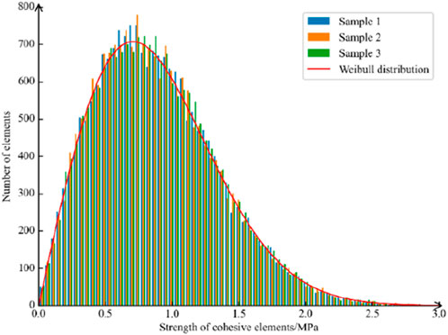
Figure 6. Comparison of three sampling results with Weibull distribution curve.
3.2 Numerical model for multiple hydraulic fracture propagation
Here, we established a two-dimensional hydraulic fracture propagation model. The model is exhibited in Figure 7. The size of the model is 20 m × 20 m, which have three clusters of perforations in the middle. The perforation direction is parallel to the maximum horizontal principal stress direction, and the spacing between each cluster of perforations is 0.5 m, with a perforation length of 0.4 m. After dividing the model into element networks using rectangular elements, zero-thickness cohesive elements were embedded between the divided matrix elements. The final model included 49214 matrix elements and 98028 cohesive elements.
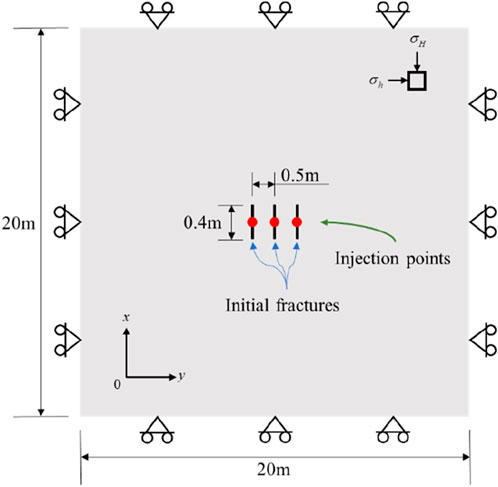
Figure 7. The numerical model for multiple hydraulic fracture propagation in heterogeneous coal reservoir.
The rock mechanics parameters, injection parameters, and in-situ stress conditions used in the simulation are presented in Table 2. The heterogeneity is assigned to the cohesive element according to the method described in Section 3.1. Considering that when m=20, the coal reservoir is approximately completely homogeneous, three different heterogeneous levels of coal reservoirs are set: strong, medium, and weak. Each heterogeneous level of coal reservoir is set with three different heterogeneity coefficients. Therefore, a total of nine coal reservoir models with different degrees of heterogeneity are established as follows: strong heterogeneous coal reservoir (m=1.5, 1.8, 2), medium heterogeneous coal reservoir (m=3, 5, 8), and weak heterogeneous coal reservoir (m=12, 16, 20).
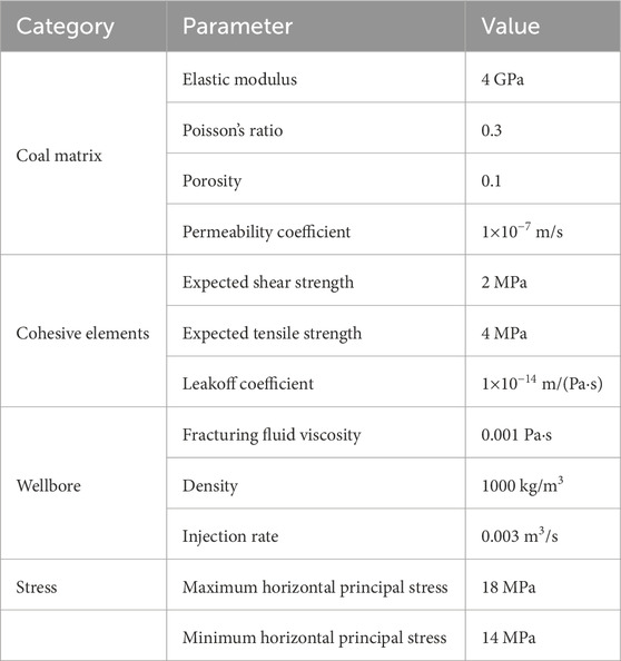
Table 2. Main parameters used in the numerical simulation.
4 Results
4.1 The morphology and evolution process of fracture network
The fracture network morphology of different heterogeneous coal reservoirs after 20 s is depicted in Figure 8. To display the fracture morphology more clearly, all cloud maps are the results of deformation amplification by 30 times. It can be seen that there are significant differences in the morphology of fracture networks under different degrees of heterogeneity. When the heterogeneity level of the coal reservoir was strong (m=1.5, 1.8, 2.0), the fracture network morphology was tortuous but the deflection angle was small, and more secondary fractures were generated. When the heterogeneity level of the coal reservoir was medium (m=3.0, 5.0, 8.0), the continuity of the main fractures became stronger, and the deflection angle of some main fractures increased. When the heterogeneity level of the coal reservoir was weak (m=12.0, 16.0, 20.0), the morphology of the fracture network underwent substantial changes, which resulted in major fractures with larger deflection angles. Some major fractures even extended perpendicular to the direction of maximum principal stress. As the heterogeneity of the coal reservoir weakens, the reason for the gradual increase in the deflection angle of the main fracture may be that when the heterogeneity of the coal reservoir is strong, there are more fracture elements with weak mechanical properties in the coal reservoir, which are controlled by the maximum horizontal principal stress during the fracturing process leading to the formation of secondary fractures with smaller deflection angle. These secondary fractures can easily connect with the main fracture during the fracturing process, thus they control the deflection direction of the main fracture. Therefore, in coal reservoirs with strong heterogeneity, the deflection angle of the main fracture was small. After the heterogeneity of the coal reservoir weakened, the mechanical properties of the fracture elements in the reservoir were almost uniform. Hence, the local stress disturbance caused by the expansion of the main fractures makes it difficult for the secondary fractures to initiate, and the main fracture gradually deviates from the maximum principal stress direction due to the strong stress interference during multiple hydraulic fractures.
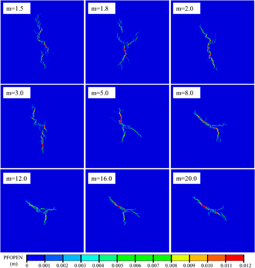
Figure 8. The fracture network morphology in different heterogeneous coal reservoirs with an injection time of t=20 s.
Although the final fracture network morphology varied under different heterogeneous coal reservoir conditions, there were still similarities in the evolution process. In Figure 9, m=1.8, 5, and 16 are analyzed as representatives of strong, medium, and weak heterogeneous coal reservoirs. It can be observed that in the early stage of fracturing, a large number of secondary fractures are generated in the middle area of the fractures. This is due to the heterogeneity of the mechanical properties of coal reservoir. Strong stress interference causes the elements around the perforation with weak mechanical properties to initiate, resulting in many isolated secondary fractures around the main fracture. Note that some secondary fractures may not necessarily be in the area where the fracturing fluid flows through, indicating that the formation of fractures is not only due to changes in pore pressure caused by fracturing fluid injection but also possibly due to stress interference between fractures. Some secondary fractures were unable to connect with the main fracture during the fracturing process, leading to discontinuous fracture phenomena (as marked in Figure 9). In coal reservoirs with stronger heterogeneity, this phenomenon was more obvious. This was because the heterogeneity of the coal reservoir was stronger, and the proportion of elements with weaker mechanical properties was also higher, which made it easier to initiate and extend under stress interference. Although all three initial fractures could initiate and form a network of fractures in the early stage of fracturing in different heterogeneous coal reservoirs, as the main fractures on both sides expanded, the middle main fracture could not further expand and form a main fracture under stress interference.
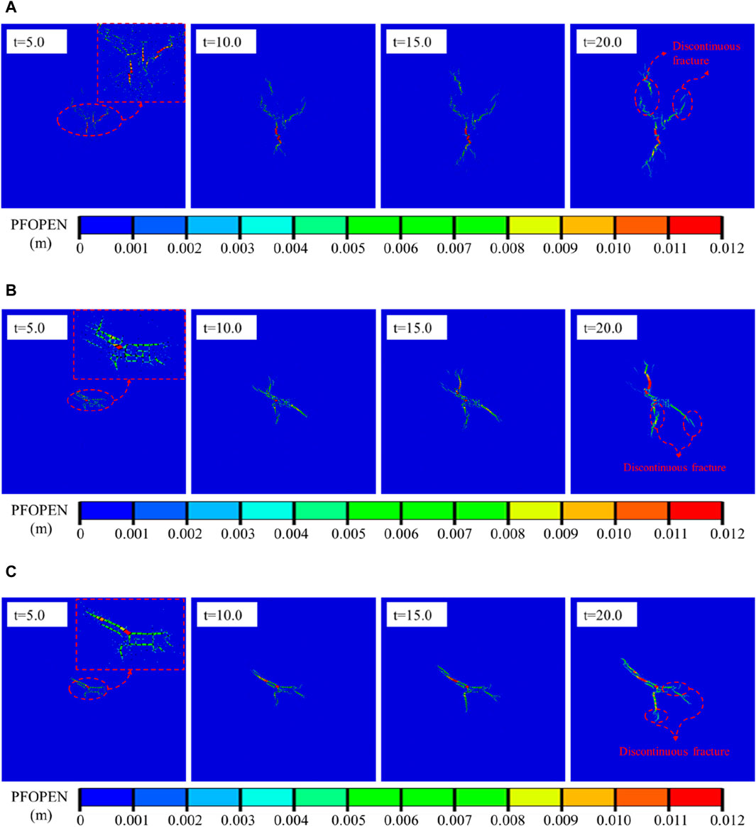
Figure 9. The evolution diagram of fracture networks in different heterogeneous coal reservoirs: (A) m=1.8, (B) m=5.0, (C) m=16.0.
4.2 Pressure curve at the injection point
The pressure-time curves at the injection points of different heterogeneous coal reservoirs were extracted from the numerical simulation results (Figure 10). From Figure 10A, it can be seen that in reservoirs with different degrees of heterogeneity, the evolution trend of pore pressure curves is almost similar, which can be divided into the following three stages: 1) The stage of sudden decrease after the pressure rises to its peak: With the continuous injection of fluid, the pressure in the initial fracture continuously accumulates, and under the action of pressure, the width of the fracture continuously widens until the fracture pressure is reached, and the fracture begins to expand. Because the pressure required for fracture propagation is smaller than the pressure required for fracture initiation, a substantial pressure drop is observed. 2) The stage of small amplitude fluctuation of pressure curve: Owing to the presence of coal reservoir heterogeneity, a small amplitude fluctuation is observed in the pressure curve. At this stage, hydraulic fractures constantly turn and connect with each other, and the shape of the fracture network becomes more complex. 3) The stage of stable pressure rise: With the continuous increase of injection time, the continuous injection of fluid leads to a continuous increase in net pressure within the expanded fracture, which further expands the fracture network.
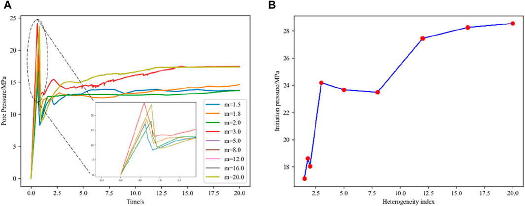
Figure 10. The pressure curve at the injection point under different heterogeneity coefficient. (A) The pore pressure variation with time under different heterogeneity coefficient (B) The fracture pressure under different heterogeneity coefficient.
However, in reservoirs with different degrees of heterogeneity, significant changes occurred in fracture pressure. Figure 10B shows the fracture pressure curve under different heterogeneity coefficient. Overall, as m increases (coal reservoir heterogeneity decreases), the fracture pressure gradually increases and finally stabilizes at a certain value. This may be due to the fact that when m is small (with strong reservoir heterogeneity), there are more fracture elements with weak mechanical properties, and these weak elements are more likely to be destroyed and connected during the fracturing process. Hence, it is difficult to maintain pressure at the injection point in reservoirs with strong heterogeneity, resulting in lower fracture pressure; As m increases, the heterogeneity of the coal reservoir weakens, and the weak fracture elements in the reservoir decrease. Thus, the fracture pressure at the injection point exhibits an upward trend; As m further increases, the coal reservoir becomes closer to a completely homogeneous reservoir, and the mechanical properties of the fracture elements in the reservoir are consistent. Therefore, the fracture pressure ultimately stabilizes at a certain value. Moreover, it should be noted that the fracture pressure shows a stepwise upward trend. According to the classification in Section 3.2, the fracture pressure is similar in reservoirs with the same heterogeneity level, and when the heterogeneity level of the reservoir changes, the fracture pressure will increase in a stepped manner.
5 Discussion
The significant impact of heterogeneity on the evolution of fracture networks and pressure curves was analyzed in Section 4. However, other factors such as construction parameters including injection rate and perforation spacing can also have a significant impact on the propagation of hydraulic fractures. To explore the impact of changes in these parameters on multiple hydraulic fracture propagation in heterogeneous coal reservoirs, numerical simulations were conducted under the condition of reservoir heterogeneity coefficient m=5. When studying the impact of a certain parameter on hydraulic fracturing, the value of that parameter was changed and other parameters were kept fixed.
5.1 Injection rate
To investigate the impact of injection rate on multiple hydraulic fracture propagation in heterogeneous coal reservoirs, numerical simulations were conducted with a heterogeneity coefficient of m=5 for injection rate equal to 0.001 m3/s, 0.002 m3/s, 0.003 m3/s, 0.004 m3/s, and 0.005 m3/s. Figure 11 depicts the morphology of the fracture network under different injection rate when the injection time is 15 s. It can be seen that as the injection rate increases, the morphology of the fracture network changes from multiple fractures to single fractures and then to multiple fractures. Hence, it is reasonable to infer that an excessively high injection rate does not necessarily mean a complex fracture network.
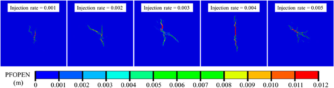
Figure 11. The fracture morphology diagram under the conditions of reservoir heterogeneity m=5 with different injection rate at an injection time of 15 s.
Figure 12 exhibits the curve of the fracture pressure at the injection point under different injection rate, indicating a positive correlation between injection rate and fracture pressure. This is because as the injection rate increases, the energy of the fracturing fluid increases, but the filtration loss and resistance loss along the way of the fracturing fluid flow inside the fracture are fixed value. Therefore, as the flow rate increases, it is easier to maintain pressure inside the fracture and the fracture pressure is also larger.
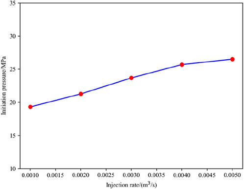
Figure 12. The fracture pressure under different injection rate.
According to previous research results, stress disturbances greater than 1 MPa may have an impact on the propagation of hydraulic fractures (Zhao et al., 2015; Yu et al., 2017). Thus, we defined the area with an increase in σh (the minimum horizontal principal stress) greater than 1 MPa as the fracturing disturbance area, and the fracturing disturbance areas of heterogeneous coal reservoirs with different injection rate were obtained accordingly (see Figure 13). Overall, the injection rate had a substantial effect on the fracturing disturbance area. As the injection rate increased, the fracturing disturbance area of the reservoir gradually increased. The fracturing disturbance area of the reservoir had the following characteristics: 1) The fracturing disturbance area was always concentrated at the tip of the main fracture; 2) The fracturing disturbance areas at the tips of different main fractures were prone to converge and thus to form a large area of fracturing disturbance; 3) The fracturing disturbance area generated by the main fracture tip had a double wing shape, and the fracturing disturbance area formed by the convergence of multiple fracture tips had a quasi square shape.
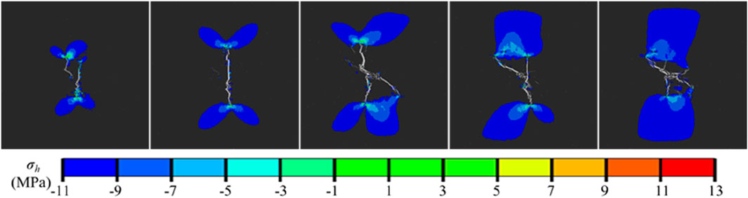
Figure 13. The fracturing disturbance area under different injection rate.
Overall, when conducting multi-stage fracturing in horizontal well in a coal reservoir with a heterogeneity coefficient m=5, a moderate injection rate should be used. Although increasing the injection rate will increase the fracturing disturbance area, it will lead to a decrease in the complexity of the fracture network and an increase in the fracture pressure.
5.2 Perforation spacing
To investigate the effect of perforation spacing on multi-cluster fracturing of horizontal wells in heterogeneous coal reservoirs, numerical simulations were conducted under conditions of perforation spacing of 0.5 m, 1.0 m, 1.5 m, and 2.0 m. Figure 14 illustrates the fracture network morphology under different perforation spacings with an injection time of t=15 s. As the perforation spacing increased, the shape of the fracture network gradually transformed from a complex curved shape to a double-wing curved fracture. This demonstrates that an increase in perforation spacing will greatly decrease the degree of mutual interference between multiple fractures. The double-wing curved fractures obtained in heterogeneous coal reservoirs were not completely symmetrical, and the expansion of one side of the fracture was hindered when the perforation spacing was 1.5 m and 2.0 m. This is due to the discreteness of the mechanical properties of fracture elements in heterogeneous coal reservoirs, which causes the fracturing fluid to be hindered by fractures with strong mechanical properties during the injection process, ultimately resulting in an asymmetric fracture network structure. At the same time, the stress interference on the middle fracture is too large, and it is still difficult for the middle fracture to expand by increasing the perforation spacing.
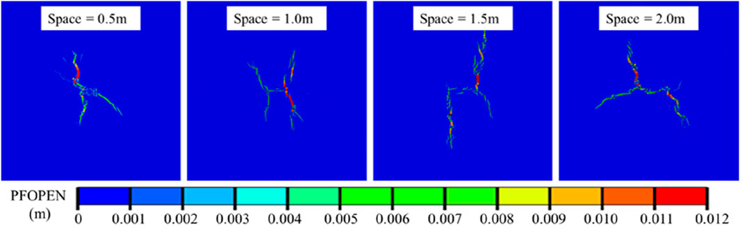
Figure 14. The fracture morphology map under the conditions of reservoir heterogeneity m=5 and different perforation spacing at an injection time of 15 s.
The perforation spacing also has a certain impact on the fracture pressure at the injection point. Figure 15 shows that as the perforation spacing increases, the fracture pressure at the injection point initially decreases and then stabilizes. When the perforation spacing increased from 0.5 m to 1.5 m, the fracture pressure decreased linearly, demonstrating that the increase in perforation spacing effectively decreased stress interference between fractures. However, as the perforation spacing continued to increase, the fracture pressure did not further decrease. This is because the stress interference of hydraulic fractures has a certain range of influence. When this range is exceeded, the mutual interference between fractures will be very limited. At this time, it will be more difficult to affect the fracture pressure at the injection point by increasing the perforation spacing.
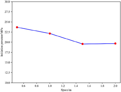
Figure 15. The fracture pressure under different perforation spacing.
Following the method explained in Section 5.1, we obtained the fracturing disturbance areas under different perforation spacings (see Figure 16). It can be observed that the fracturing disturbance area still has similar characteristics as described in Section 5.1. However, under different perforation spacing conditions, the area and shape of the fracturing disturbance area do not show significant changes.
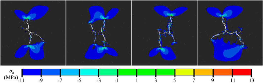
Figure 16. The fracturing disturbance areas at different perforation spacing.
In a word, when conducting hydraulic fracturing in coal reservoirs with a heterogeneity coefficient m=5, it is recommended to increase the perforation spacing appropriately, as increasing the perforation spacing will reduce the stress interference between the fractures, and at the same time, the fracture pressure will decrease.
6 Conclusion
This study simulated the multiple hydraulic fracture propagation in different heterogeneous coal reservoirs. Based on FDEM, the heterogeneity of coal reservoir was assigned through the Weibull distribution function. By numerical simulation, the following conclusions were obtained.
(1) As the heterogeneity of the coal reservoir weakened, the deflection angle of the main fracture increased and even became approximately perpendicular to the direction of the maximum principal stress. Due to the coal reservoir heterogeneity, many secondary fractures emerged in the fracture network, which resulted in significant discontinuous fracture.
(2) The fracturing disturbance area of heterogeneous coal reservoirs had the following significant characteristics: 1) The fracturing disturbance area was always concentrated at the tip of the main fracture; 2) The stress disturbance areas of different main fractures tended to converge; 3) The fracturing disturbance area generated by a single main fracture tip had a double wing shape, and the fracturing disturbance area formed by the convergence of multiple main fracture tips had a quasi square shape.
(3) When hydraulic fracturing is carried out in coal reservoirs with a heterogeneity coefficient m=5, it is recommended to use a moderate injection rate and increase the perforation spacing appropriately.
Data availability statement
The raw data supporting the conclusion of this article will be made available by the authors, without undue reservation.
Author contributions
BX: Funding acquisition, Methodology, Supervision, Writing–review and editing. XZ: Writing–original draft, Formal Analysis, Supervision. ZM: Conceptualization, Software, Writing–original draft, Visualization. XX: Writing–original draft, Visualization.
Funding
The author(s) declare that financial support was received for the research, authorship, and/or publication of this article. This work was supported by a grant from Chongging Research Program of Technological Innovation and Application Demonstration (Grant No. CSTB2022TIAD-KPX0135).
Conflict of interest
The authors declare that the research was conducted in the absence of any commercial or financial relationships that could be construed as a potential conflict of interest.
Publisher’s note
All claims expressed in this article are solely those of the authors and do not necessarily represent those of their affiliated organizations, or those of the publisher, the editors and the reviewers. Any product that may be evaluated in this article, or claim that may be made by its manufacturer, is not guaranteed or endorsed by the publisher.
References
Akpanbayeva, A., and Issabek, T. (2023). Assessing a natural field of rock mass stress by means of in-situ measurements within Vostochnaya Sary-Oba deposit in Kazakhstan. Min. MINERAL DEPOSITS 17 (3), 56–66. doi:10.33271/mining17.03.056
Camanho, P., Davila, C., and de Moura, M. F. (2003). Numerical simulation of mixed-mode progressive delamination in composite materials. J. Compos. Mater. 37, 1415–1438. doi:10.1177/0021998303034505
Carrier, B., and Granet, S. (2012). Numerical modeling of hydraulic fracture problem in permeable medium using cohesive zone model. Eng. Fract. Mech. 79, 312–328. doi:10.1016/j.engfracmech.2011.11.012
Dou, F., and Wang, J. G. (2022). A numerical investigation for the impacts of shale matrix heterogeneity on hydraulic fracturing with a two-dimensional particle assemblage simulation model. J. Nat. Gas Sci. Eng. 104, 104678. doi:10.1016/j.jngse.2022.104678
Duan, K., Li, Y., and Yang, W. (2020). Discrete element method simulation of the growth and efficiency of multiple hydraulic fractures simultaneously-induced from two horizontal wells. Geomechanics Geophys. Geo-Energy Geo-Resources 7 (1), 3. doi:10.1007/s40948-020-00196-4
Ehlers, W., and Luo, C. (2017). A phase-field approach embedded in the Theory of Porous Media for the description of dynamic hydraulic fracturing. Comput. Methods Appl. Mech. Eng. 315, 348–368. doi:10.1016/j.cma.2016.10.045
Guo, J., Zhao, X., Zhu, H., Zhang, X., and Pan, R. (2015). Numerical simulation of interaction of hydraulic fracture and natural fracture based on the cohesive zone finite element method. J. Nat. Gas Sci. Eng. 25, 180–188. doi:10.1016/j.jngse.2015.05.008
Lei, Q., and Gao, K. (2018). Correlation between fracture network properties and stress variability in geological media. Geophys. Res. Lett. 45 (9), 3994–4006. doi:10.1002/2018gl077548
Li, M., Guo, P., Stolle, D. F., Liang, L., and Shi, Y. (2020). Modeling hydraulic fracture in heterogeneous rock materials using permeability-based hydraulic fracture model. Undergr. Space 5 (2), 167–183. doi:10.1016/j.undsp.2018.12.005
Li, X., Xiao, W., Qu, Z., Guo, T., Li, J., Zhang, W., et al. (2018). Rules of fracture propagation of hydraulic fracturing in radial well based on XFEM. J. Petroleum Explor. Prod. Technol. 8 (4), 1547–1557. doi:10.1007/s13202-018-0436-5
Li, Y., Yang, S., Zhao, W., and Zhang, J. (2018). Experimental of hydraulic fracture propagation using fixed-point multistage fracturing in a vertical well in tight sandstone reservoir. J. Petroleum Sci. Eng. 171, 704–713. doi:10.1016/j.petrol.2018.07.080
Liao, S., Hu, J., and Zhang, Y. (2022). Investigation on the influence of multiple fracture interference on hydraulic fracture propagation in tight reservoirs. J. Petroleum Sci. Eng. 211, 110160. doi:10.1016/j.petrol.2022.110160
Luo, F., Gao, S., Xu, Z., Dong, E., Diao, Y., and Sang, Y. (2023). Mechanical behavior and tension-shear failure mechanism of fractured rock mass under uniaxial condition. Bull. Eng. Geol. Environ. 82 (8), 314. doi:10.1007/s10064-023-03330-0
Ni, L., Zhang, X., Zou, L., and Huang, J. (2020). Phase-field modeling of hydraulic fracture network propagation in poroelastic rocks. Comput. Geosci. 24 (5), 1767–1782. doi:10.1007/s10596-020-09955-4
Parvizi, H., Rezaei-Gomari, S., Nabhani, F., and Turner, A. (2017). Evaluation of heterogeneity impact on hydraulic fracturing performance. J. Petroleum Sci. Eng. 154, 344–353. doi:10.1016/j.petrol.2017.05.001
Sun, C., Zheng, H., and David Liu, W. (2020). Study on dynamic propagation of hydraulic fractures in enhanced thermal reservoir. Eng. Fract. Mech. 236, 107207. doi:10.1016/j.engfracmech.2020.107207
Tang, H., Li, S., and Zhang, D. (2018). The effect of heterogeneity on hydraulic fracturing in shale. J. Petroleum Sci. Eng. 162, 292–308. doi:10.1016/j.petrol.2017.12.020
Wangen, M. (2011). Finite element modeling of hydraulic fracturing on a reservoir scale in 2D. J. Petroleum Sci. Eng. 77 (3), 274–285. doi:10.1016/j.petrol.2011.04.001
Wei, S., Kao, J., Jin, Y., Shi, C., Xia, Y., and Liu, S. (2021). A discontinuous discrete fracture model for coupled flow and geomechanics based on FEM. J. Petroleum Sci. Eng. 204, 108677. doi:10.1016/j.petrol.2021.108677
Wu, K., and Olson, J. (2015). Simultaneous multifracture treatments: fully coupled fluid flow and fracture mechanics for horizontal wells. SPE J. 20, 337–346. doi:10.2118/167626-pa
Wu, M., Gao, K., Liu, J., Song, Z., and Huang, X. (2022). Influence of rock heterogeneity on hydraulic fracturing: a parametric study using the combined finite-discrete element method. Int. J. Solids Struct. 234-235, 111293. doi:10.1016/j.ijsolstr.2021.111293
Yang, W., Geng, Y., Zhou, Z. q., Li, L. p., Gao, C. l., Wang, M. x., et al. (2020). DEM numerical simulation study on fracture propagation of synchronous fracturing in a double fracture rock mass. Geomechanics Geophys. Geo-Energy Geo-Resources 6 (2), 39. doi:10.1007/s40948-020-00162-0
Yu, Y., et al. (2017). Analysis on stress shadow of mutual interference of fractures in hydraulic fracturing engineering. Chin. J. Rock Mech. Eng. 36 (12), 2926–2939. doi:10.13722/j.cnki.jrme.2017.0405
Zhao, J., et al. (2015). The analysis of crack interaction in multi-stage horizontal fracturing. Nat. Gas. Geosci. 26 (3), 533–538. doi:10.11764/j.issn.1672-1926.2015.03.0533
Keywords: multi-cluster fracturing, heterogeneous coal reservoir, combined finite-discrete element method (FDEM), hydraulic fracture propagation, coalbed methane
Citation: Xia B, Zhang X, Ma Z and Xu X (2024) Numerical simulation of multiple hydraulic fracture propagation in heterogeneous coal reservoirs based on combined finite-discrete element method. Front. Earth Sci. 12:1411129. doi: 10.3389/feart.2024.1411129
Received: 02 April 2024; Accepted: 23 April 2024;
Published: 09 July 2024.
Edited by:
Vasyl Lozynskyi, Dnipro University of Technology, UkraineReviewed by:
Volodymyr Falshtynskyi, National Mining University of Ukraine, UkraineJintang Wang, China University of Petroleum, China
Copyright © 2024 Xia, Zhang, Ma and Xu. This is an open-access article distributed under the terms of the Creative Commons Attribution License (CC BY). The use, distribution or reproduction in other forums is permitted, provided the original author(s) and the copyright owner(s) are credited and that the original publication in this journal is cited, in accordance with accepted academic practice. No use, distribution or reproduction is permitted which does not comply with these terms.
*Correspondence: Zikun Ma, MjAyMTIwMDEwMDdAc3R1LmNxdS5lZHUuY24=