 Haifeng Zhou1
 Qingxiang Huang
 Yanpeng He
- 1China Energy Shendong Coal Group Co., Ltd., Shenmu, Shaanxi, China
- 2School of Energy Engineering, Xi’an University of Science and Technology, Xi’an, Shaanxi, China
In multi-seam mining, as mining ranges expand and depths increase, the strong ground pressure exerted on the lower coal-seam working faces (WFs) or roadways by coal pillars (CPs) and the hard roof between the interburdens becomes increasingly severe, leading to periodic roof-fall accidents. This study focused on the 42108 WF of the 4–2 coal seam in the Buertai Coal Mine of Shandong mining. It combined field tests, theoretical research, and numerical calculations to investigate the superposition or amplification of ground pressure as WF traversed the CP with the hard roof between interburdens. The ground pressure behavior of WF entering and exiting the CP stage progressed from strong to weak: exiting the CP > under the CP > entering the CP, with the CP stage being prone to a strong ground pressure occurrence. We proposed the influence mechanism of strong ground pressure and a seesaw structural mechanics model under the mining conditions with parallel CPs and hard roofs. The relationship between the geometric structure movement and stress evolution of the seesaw space of the overlying hard roof was analyzed, revealing the mechanism behind stress increase, evident damage, and the likelihood of dynamic disasters within 5–10 m from the CP boundary of the WF. The stress concentration factor (SCF) of the advance abutment pressure in the coal wall was the primary controlling factor determining seesaw instability, effectively ensuring safe and efficient mining practices. This research holds significant theoretical importance and practical engineering value for controlling strong mine pressure under the overlying CPs and hard roofs.
1 Introduction
The Shenfu Dongsheng Coalfield ranks among the world’s largest coal fields, primarily comprising shallow coal seams with depths less than 400 m. Most primary coal seams consist of approximately three layers, spaced 20–70 m apart, falling under shallow coal-seam group mining (Kang et al., 2019; Wang et al., 2023; Dang et al., 2024). As the mining intensity and depth increase, the Shandong mining area has progressively transitioned to deeper and lower coal-seam mining, with the residual pillars in the gob exerting significant influence on lower coal-seam mining. The strata control faces two principal challenges: the concentrated stress of the pillars in the CP affecting safety in production (Maleki, 2017; Huang et al., 2019a; Huang and He, 2019) and the formation of surface cracks due to coal-seam group mining, causing substantial environmental damage (Huang et al., 2019b; Wang et al., 2021).
In the Buertai Coal Mine, the main roof of the interburden comprises medium–fine grained sandstone, which is characterized by its hardness and thickness, rendering it moderately stable and resistant to collapse. With a distance of approximately 70 m between two coal seams, the WF (working face) is subject to stress concentration from the remaining CPs (coal pillars) during lower coal-seam mining. Numerous domestic scholars have extensively researched (Yu, 2010; Kong, 2020; Song et al., 2021) the behavior of mine pressure exerted by the overlying remaining CPs on the underlying WF. For instance, Zhu and Yu (2018) and Zhu et al. (2019) investigated WF support crushing, surface step collapse, and mine earthquake disasters during mining under shallowly buried and closely spaced coal seams in China. They explored the dynamic instability process of CP groups and the mechanisms underlying support crushing. Similarly, Xue et al. (2021) established a physical similarity model of thick and hard rock WF, analyzing the strata movement characteristics in extra-thick coal seams. Jia et al. (2020) explored the optimal layout of coal seam mining roadways beneath residual CPs, determining, through theoretical calculations and MATLAB software analysis of the mechanical distribution characteristics, that the maximum failure depth of the 2# coal seam floor influenced by advanced abutment pressure is 23.7 m. Furthermore, Du (2019) optimized the narrow CP dimensions of the WF under close-distance coal seam goafs, considering the influence of different CP widths on the coal and rock stress distribution. Based on the theory of internal stress fields and limit equilibrium zones, they determined the lower and upper limits of narrow CP dimensions to be 4 m and 7 m, respectively. This body of research illustrates that residual CPs from overlying coal seams not only induce concentrated stress effects but also trigger secondary movement, thereby increasing the disturbance space of the underlying WF.
In addressing the mine pressure behavior within the stress-affected zone of the CP section in the WF, numerous scholars have conducted extensive research. For instance, Cheng et al. (2020) investigated the influence of the CP width and overburden characteristics on the deformation of the surrounding rock in gob-side entry retaining. Dai et al. (2020) proposed an intelligent analysis method for CP stability. Jiang et al. (2020), through theoretical calculations and discrete element simulation, analyzed the structural characteristics and internal stress field distribution in the gob-side roadway, noting that the maximum bending moment of the main roof rock beam increases with the lengthening of the suspended roof. Notably, due to the substantial thickness and weight of the main roof, the internal stress field in thick and hard main roofs surpasses that of conventional WFs. Similarly, Bai et al. (2021) explored the significant linkage disaster-causing effect of chain instability among the remaining CPs in the goaf. They proposed key pillar-side filling control technology, elucidated the mechanism of key pillar-side filling, and determined technical parameters such as material, strength, width, and shape of the pillar-side filling body. Xu et al. (2019) analyzed the mechanism and control technology of narrow CP failure in WFs by integrating theoretical analysis, numerical simulation, and field measurement. Bai et al. (2017) investigated the influence of a hard roof on mining roadway failure, while He et al. (2016) scrutinized the impact of a hard roof on mine pressure behavior and mine earthquake events. Furthermore, Zhu et al. (2017) addressed hydraulic support crushing, coal wall spalling, and serious surrounding rock deformation in gob-side entry under conditions of extra-thick coal seams and multi-layer hard roofs. Their mine pressure monitoring revealed the extensive influence range of mining stress and the formation of large structures in overburden rock due to multi-layer hard roofs, highlighting the combined action of substantial mining space and multi-layer hard roofs as the primary cause of strong pressure in the WFs. Yang et al. (2016), Zhang et al. (2019), and Zheng and Kong (2020) investigated the roof breaking movement law of WFs with hard roofs, establishing a deep beam structure model with an initial weighting interval of 47.57 m. Numerical simulations indicated an average periodic weighting interval of 20 m, with field-measured initial weighting intervals of 46 m and periodic weighting intervals of 18.7–20.8 m, resulting in a pressure influence range of 1.7–5.6 m. Gao et al. (2018), Chen et al. (2022), Li J. W. et al. (2023), and Qin et al. (2024) examined the rock pressure mechanism of fracture instability in hard rock in the far field, suggesting that the large expansion radius of ground fracturing can significantly reduce hard roof fracture steps, thereby reducing WF pressure strength with remarkable fracturing effects (Huang et al., 2017; Li et al., 2020; Feng et al., 2022; Li et al., 2024). This approach proves effective and innovative in achieving strong mine pressure control (Jiang et al., 2024; Tang et al., 2024; Zheng et al., 2024) by enhancing WF weighting management through a deeper understanding of hard roof fracture characteristics, rock mechanical properties, and intelligent early warning systems (Li X. S. et al., 2023; Ren et al., 2023; Cao et al., 2024). In addressing the strong mine pressure dynamic load support, the stability of the surrounding rock is enhanced by leveraging large deformation anchor cable support techniques akin to tunnel construction (Yin et al., 2021; Li G. et al., 2023). In addition, through the way of coal gangue filling mining (Wu et al., 2023; Fang et al., 2023; Wu et al., 2024; He et al., 2024), on one hand, the underground gangue is treated, and on the other hand, the mining space is reduced. Improving the support capacity of the roof structure on both sides of the coal pillar and reducing the degree of concentrated stress can effectively alleviate the concentrated stress of the CP mining in the lower coal seam (Shi H. et al., 2023; Shi Hao et al., 2023).
The Buertai Coal Mine exhibits characteristics of significant mining depth, intense mining disturbance, and substantial influence of CP remnants from the overlying coal seams and hard roofs. During the mining process of the 4–2 coal seam, the intensity of strong mine pressure is pronounced, posing a serious threat to mine safety and production. Consequently, studying the mechanisms of strong ground pressure in the deep areas of the Buertai Coal Mine, analyzing prevention and control methods to mitigate or eliminate strong mine pressure accidents, and effectively managing strong ground pressure in the WFs of the Buertai Coal Mine and the broader Shandong mining area are highly significant.
2 Engineering background and research methods
2.1 Overview of the study area
The average burial depth of the 4–2 coal seam (lower coal seam) measures 377 m, which is approximately 70 m distant from the upper goaf. Due to the influence of the CP, the WF experiences numerous instances of strong ground pressure during lower coal-seam mining. The 42108 WF exhibits a strike length of 5,170 m and a width of 310 m. Its roof consists of sandy mudstone and fine-grained sandstone. Notably, the 42108 WF consists of parallel CPs from the upper coal seam section, as illustrated in Figure 1. At the point when the 42108 WF advanced to 1,346 m, during the WF periodic weighting, the support working resistance sharply increased, culminating in the collapse of the right column of the 78# support. The influence of the CP within a 100-m range ahead of the WF results in significant deformation or failure and instability of the roadway’s surrounding rock, which is characterized by roof crushing, sinking, side drumming, and floor drumming, as depicted in Figure 2.

Figure 1. CP arranged parallel to the lower coal seam WF.
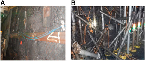
Figure 2. Strong ground pressure behavior: (A) lane side bulging; (B) pillar dumping.
The Buertai Coal Mine exhibits characteristics of considerable mining depth and substantial influence of the remaining CPs in the overlying hard roof. Moreover, the ground pressure is pronounced, significantly impacting mine safety and production. To categorize the rock strength index, the rock strength is divided into five categories based on the density, layer thickness, the product of tensile and compressive strengths, and the RQD value of the rock. A strength index less than 21 denotes a V-type extremely weak rock stratum, while a strength index between 21 and 736 indicates class IV soft rock stratum. Strength indices between 736 and 4,725 classify it as a class III medium–hard rock stratum, whereas indices between 4,725 and 15,552 denote class II hard rock strata. A strength index exceeding 15,552 is classified as class I extremely hard rock stratum. Table 1 presents detailed information regarding the classification.
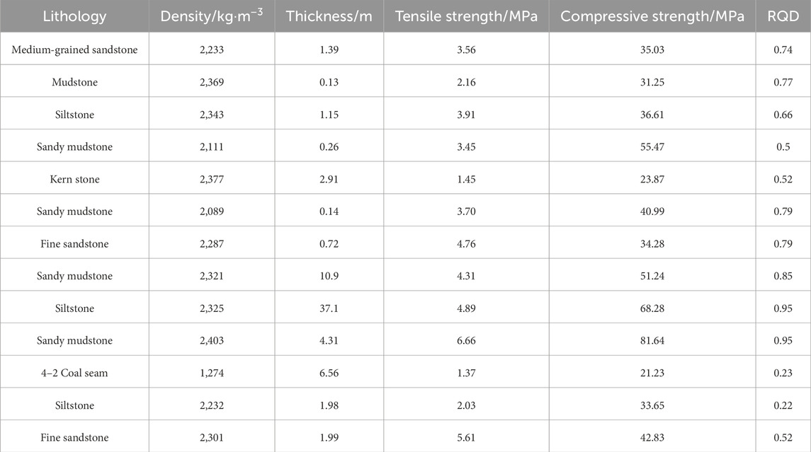
Table 1. Classification index of the overburden strength in the 4–2 coal seam.
Table 1 highlights that the overlying strata primarily comprises sandy mudstone and siltstone, mostly from IV to V rock strata. Notably, the main roof comprises class I siltstone and is 37.1 m thick, which is classified as an extremely hard rock stratum. The immediate roof consists of class II sandy mudstone, is 4.31 m thick, and is categorized as hard rock strata, while the coal seam floor is composed of class IV coarse-grained sandstone. Therefore, the WF’s roof in the study area is a hard roof, exerting significant influence during the CP mining process.
Examining the diagram revealed the necessity for multiple entries and exits into the CP. The ground pressure behavior of the WF is significantly influenced by the CP stress concentration. Field measurements indicate notable disparities in ground pressure behavior as the WF enters and exits parallel CPs. Upon entry into parallel CPs, ground pressure is not prominent. Conversely, upon exiting parallel CPs, ground pressure escalates significantly, prompting the activation of the safety valve in the WF’s hydraulic support. Therefore, investigating differences in the overburden structure during WF entry and exit from CPs and elucidating the mechanical mechanisms underlying the variations in ground pressure behavior are crucial.
2.2 On-site ground pressure monitoring
When the 42106 WF enters the middle of the parallel CP, noticeable roof weighting occurs, accompanied by severe spalling and stripping of the WF roof. The roof experiences three significant periodic weightings with intervals of 13–18 m and a maximum weighting resistance of 51.6 MPa. Notably, the maximum load area shifts toward the side of the CP when the support under the upper coal seam goaf undergoes periodic weighting, resulting in a noticeable weakening of pressure on the supports 100 to 150#. However, upon exiting the CP by 5 m, a distinct strong ground pressure emerges, leading to direct subsidence of the roof beneath the CP. The maximum subsidence reaches 300 mm, with the maximum pressure strength of 51.2 MPa, as depicted in Figure 3.
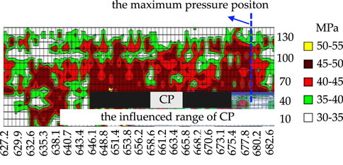
Figure 3. Ground pressure curved surface when the WF exits the CP.
2.3 Proposal of the seesaw structure model
Based on the “voussoir beam” theory and extensive three-dimensional simulation tests, the hard main roof between the lower and upper coal seams will horizontally break into an “O–X” pattern, forming an approximate “fan-shaped plate structure” in the middle of the WF. The stability of this “fan-shaped plate structure” above the WF is analyzed according to the “S–R” theory of voussoir beams, yielding an instability criterion for the structure. Due to the mutual penetration of fracture lines, roof caving and sinking easily lead to instability in the overburden structure. The seesaw structure model of the main roof at different CP stages is depicted in Figure 4.
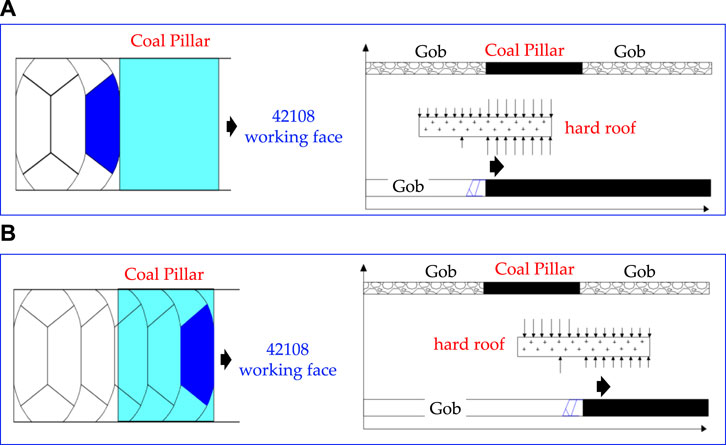
Figure 4. Seesaw structure model of the WF entering and exiting the CP at different stages: (A) WF entering the CP; (B) WF exiting the CP.
The passage of the WF through the CP is divided into three stages: “entering CP,” “under CP,” and “exiting CP.” The roof breaking and stress situation are illustrated in Figure 5. When the lower coal seam WF enters and exits the CP, the main roof forms a “seesaw structure” with two fulcrums: one primary fulcrum located in the coal wall and one auxiliary fulcrum provided by the hydraulic support.
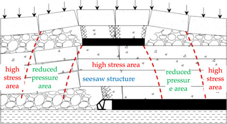
Figure 5. Seesaw structure model of the WF.
The support force of the coal wall to the main roof breaking block is assumed to be evenly distributed, positioning the main fulcrum of the “seesaw structure” in the coal wall approximately at the midpoint between the coal wall and the fracture position. The auxiliary fulcrum provided by the hydraulic support is situated approximately above the pillar. Although the “seesaw structure” is a development and application of the “voussoir beam” hinged structure when the WF passes through parallel CPs, some differences exist between the two. In the “voussoir beam” hinged structure, the stress of the key block is assumed to be uniform, whereas in the “seesaw structure,” at different stages of CP entry and exit, the stress of the key block is dynamic. Upon WF entry into the CP, the stress concentration factor (SCF) of the hard roof ahead of the WF exceeds 1 due to the CP stress concentration, while the SCF of the hard roof behind the WF is less than 1. Therefore, when support resistance is not substantial, it ensures that the fan-shaped seesaw does not rotate violently, preventing WF support-crushing accidents. However, upon CP exit by the WF, the SCF of the hard roof behind the WF significantly increases due to CP stress concentration. This increase in SCF makes the main roof prone to shear failure upon exiting the CP, rendering the coal wall incapable of supporting the main roof. Inadequate WF support resistance may lead to roof-cutting subsidence, resulting in support-crushing accidents.
2.4 Construction of the CDEM model
The deformable block discrete element model, developed based on the rigid block discrete element, can be directly transformed from the calculation model of a continuous medium to the discontinuous calculation model, known as the continuum-based distinct element method (CDEM). In this study, CDEM numerical simulation software is employed to simulate the evolution of the stope structure and the law of mine pressure during coal-seam mining in the Buertai Coal Mine. The thickness of mining in the 42108 WF ranges from 3.46 to 7.05 m, with an average of 6.13 m. The WF length is 300.3 m, the strike length is 4,807.9 m, and the burial depth is 470 m, with an inter-distance of 70 m between the seams.
To simplify numerical calculations, this study establishes a model featuring a 4–2 coal seam and an overburden height of 160 m and a model width of 1,000 m. Additionally, a vertical uniform pressure of 7.5 MPa, equivalent to the weight of a 300-m rock layer, is applied above the model. Based on the comprehensive borehole data, a simplified geological model and the corresponding numerical calculation model are depicted in Figure 6.

Figure 6. Numerical model established by CDEM.
The upper boundary of the numerical model primarily relates to the gravity of the overburden rock, with a load q = γh = 7.5 MPa. It is movable in the x-direction, while the y-direction features fixed-hinge support, i.e., v = 0. The boundary conditions on both sides of the model are simplified as displacement boundary conditions, allowing movement in the y-direction, with the x-direction having fixed-hinge support, i.e., u = 0. The physical and mechanical parameters of each rock layer in the numerical simulation model are outlined in Table 2. The maximum tensile stress and Mohr–Coulomb strength criterion are selected as the criteria for judging the failure of the rock and coal seam (Huang et al., 2019a; Jiang et al., 2024; Wu et al., 2024).
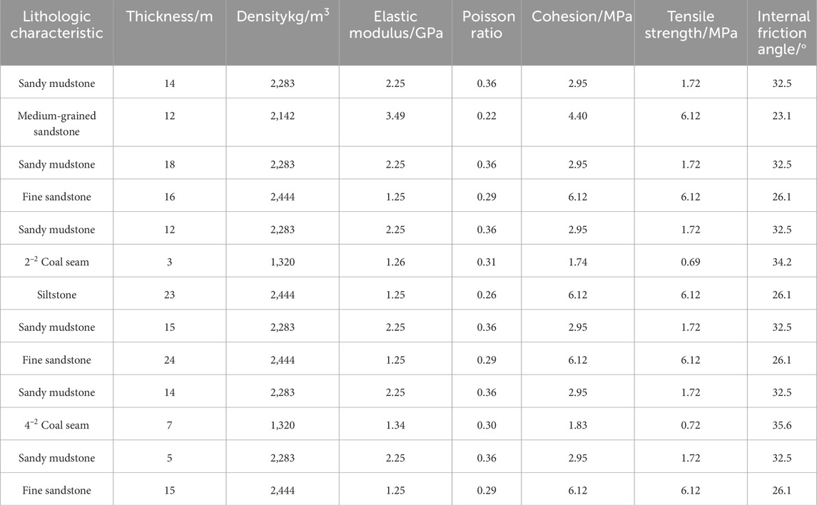
Table 2. Mechanical parameters of coal rock in the study area.
An observation line is established in the CP and the sub-key stratum 1 between the layers to monitor the stress evolution characteristics of the overlying strata during coal-seam mining, with each measuring point spaced at 1-m intervals. During WF mining, the support command is utilized to determine the support efficiency provided by the hydraulic support.
3 Results
3.1 Mechanical analysis of the seesaw when the WF enters the CP
As depicted in Figure 7A, when the WF initiates entry into the CP, the seesaw structure of the main roof (key block A) undergoes mechanical analysis. Here, QcE represents the joint force of key block A bearing the load on the goaf side, while QmE denotes the joint force of key block A experiencing front abutment pressure in the coal wall. Additionally, G signifies the weight of key block A, T represents the horizontal extrusion pressure between the key blocks, FsE indicates the initial support resistance (ISR), and PmE stands for the support force of the coal wall as shown in Figure 7B.
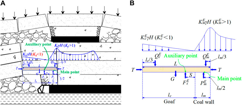
Figure 7. Force analysis of the seesaw when the WF enters the CP: (A) stress distribution of the overlying strata in the stage when the WF enters the CP; (B) roof mechanical model analysis.
Key block A sustains load QcE on the goaf side, generating a counterclockwise torque due to its weight G. Simultaneously, the support force FsE and key block A produce a clockwise moment against the front abutment pressure QmE in the coal wall, impeding the rotation of the seesaw structure (key block A).
The magnitude of load QcE on the goaf side directly influences the ease of rotation of the seesaw structure (key block A) toward the goaf. Conversely, greater support force Fs and the front abutment pressure QmE in the coal wall reduce the likelihood of the seesaw structure rotation. Upon initiation of WF entry into the CP, the SCF KcE of the seesaw structure (key block A) bearing the load on the goaf side is less than 1, indicating a small QcE. Conversely, SCF KmE of the abutment pressure in front of the coal wall exceeds 1, signifying a large QmE. Therefore, minimal support force is required to control the seesaw structure rotation, resulting in a low ground pressure on the WF.
According to the stress analysis of the “seesaw structure” during WF entry into the CP, the equilibrium equation can be formulated as follows:
Here, M denotes coal thickness, m; γ represents the average bulk density of the rock, kN/m3; H denotes the coal-seam buried depth, m; s denotes the distance between the hydraulic prop of the WF and the coal wall, m; L denotes the main roof thickness, m; lc denotes the main roof weighting interval, m; lc represents the saw hanging length, m; lm represents the depth of the seesaw in the coal wall, m; KcO denotes the SCF of the load on the suspended side of the seesaw; KmE denotes the SCF of the abutment pressure of the seesaw in the coal wall; p denotes the supporting force of the support to the coal wall; φ represents the internal friction angle of coal, °; f denotes the friction coefficient of the contact surface; and C denotes coal cohesion, MPa.
Considering the width of the WF support, the hydraulic support’s force FsE can be derived from Formulas 1, 2 as follows:
Here, W represents the width of the hydraulic support, m.
Applying Formula 4, during WF entry into the CP, the hydraulic support’s force FsE includes the SCF Kc of the load on the suspended side of the seesaw, the SCF Km of the seesaw in the coal wall, the main roof’s weighting interval L, the depth lm of the seesaw, the thickness h of the main roof, and the buried depth H of the coal seam.
Based on the engineering geological conditions of the Buertai Coal Mine and the parameters of the hydraulic support, the following parameters are considered:
The average bulk density of rock γ = 25 kN/m3, coal-seam buried depth H = 400 m, main roof weighting interval distance L = 15 m, main roof average thickness h = 10 m, coal seam thickness M = 6 m, support width W = 2.05 m, coal seam cohesion C = 1.5 MPa, friction coefficient f = 0.4, and support force p = 0. By substituting these parameters into Formula 3, the fracture position of the main roof lm ≈ 4.0 m. Subsequently, by applying these parameters to Formula 4, the variation law of the ISR with various parameters during WF entry into the CP can be determined.
3.1.1 Influence law of the SCF on the hanging side of the seesaw
During the entry of the lower coal seam’s WF into the CP, the variation in FsE with the SCF KcE on the hanging side of the seesaw is depicted in Figure 8. As SCF KcE increases, the ISR experiences a notable increase. When the SCF KcE of the suspended side of the “seesaw structure” exceeds certain thresholds (0.5, 0.4, 0.3, and 0.2, respectively), the support force exerted by the hydraulic support surpasses its rated working resistance of 21,000 kN upon WF entry into the CP.
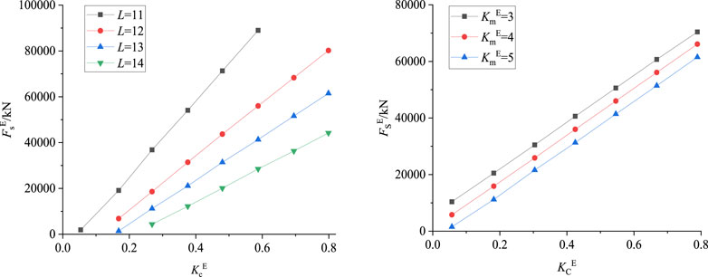
Figure 8. Variation law of FsE with SCF KcE on the hanging side of the seesaw.
Additionally, the ISR diminishes with an increase in SCF KmE of the front abutment pressure. In other words, under the combined influence of the stress concentration in the upper CP and WF mining, the abutment pressure escalates. This scenario, where QmE is large, necessitates only minimal force from the support to manage the rotation of the “seesaw structure,” resulting in reduced ground pressure on the WF.
When the SCF KcE of the suspended side load of the “seesaw structure” exceeds 0.4, the ISR will surpass its rated working resistance upon WF entry into the CP. This prompts the opening of the safety valve of the hydraulic support, support contraction, and rotation of the “seesaw structure,” leading to ground pressure. However, the goaf’s warped side, positioned below the upper gob, forms a “voussoir beam”-bearing structure with the upper key stratum 2, primarily shouldering the upper load and safeguarding the lower “seesaw structure.” Consequently, the SCF of the load on the hanging side of the seesaw remains minimal. Thus, during WF entry into the CP, the support force is generally low, and strong ground pressure is typically absent, which is consistent with measured results.
3.1.2 Influence law of the periodic weighting interval of the main roof
Drawing on the measured results of WF 42108, the periodic weighting interval falls within the range of 12–19 m. Analyzing different SCFs (KcE = 0.1, 0.2, 0.3, and 0.4) on the goaf side of the “seesaw structure” during WF entry into the CP reveals the variation in the ISR with the periodic weighting interval L, as depicted in Figure 9. Notably, as the weighting interval increases, the support force experiences rapid increase.
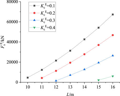
Figure 9. Variation law of FsE with the periodic weighting interval L.
For SCFs KcE = 0.1 and KcE = 0.2 on the goaf side of the seesaw structure, the support force remains below its rated working resistance within the measured weighting interval range. This indicates that the support’s safety valve will not open, and the roof will not sink. However, for SCF KcE = 0.3 on the goaf side, if the main roof weighting interval exceeds 18 m, the support force will surpass its rated working resistance, prompting the safety valve to open, potentially causing roof sinking.
3.1.3 Influence of the SCF of the front abutment pressure of the seesaw
When the WF enters the CP, the trend of FsE with SCF KmE is depicted in Figure 10. With an increase in SCF KmE, the support force gradually decreases. This decline primarily stems from the clockwise moment generated by the WF’s front abutment pressure, impeding the rotation of the “seesaw structure” toward the goaf.
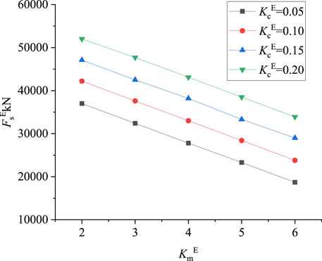
Figure 10. Variation law of FsE with s KmE in the coal wall.
Therefore, a larger SCF of the advancing coal wall results in a greater pressure borne by the seesaw structure within the coal wall, which consequently reduces its likelihood of rotation. When the WF initially enters the CP and SCF KmE > 1, the seesaw structure remains stationary, alleviating stress on the WF support.
3.1.4 Influence of the fracture position of the seesaw in the coal wall
Figure 11 illustrates the variation in the support force FsE of the WF with the fracture position L of the seesaw. With an increase in the fracture depth of the main roof, the load on the support gradually diminishes. This decline is primarily attributed to the deeper fracture position, resulting in increased support force on the seesaw structure and reduced support load.

Figure 11. Variation law of FsE with the fracture position lm of the seesaw.
3.1.5 Influence of the thickness of the main roof
When the WF enters the CP, under varying SCF conditions of the “seesaw structure” on the goaf side (KcE = 0.1, 0.2, 0.3, and 0.4), Figure 12 illustrates the trend of FsE with the main roof thickness h. With an increase in the main roof thickness h, the ISR experiences a substantial increase. This effect is observed when the SCF of the “seesaw structure” on the goaf side is KcE = 0.1 and KcE = 0.2.
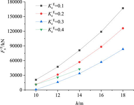
Figure 12. Variation in the support force FsE with the main roof thickness h.
Considering the geological conditions of WF, where the main roof comprises fine-grained sandstone with a thickness ranging from 6 to 17 m, the main roof thickness fluctuates during WF advancement, leading to ISR fluctuations.
3.1.6 Influence of the mining thickness
Figure 13 illustrates the ISR’s variation with the mining thickness M as the WF enters the CP. With an increase in the coal-seam mining thickness, the ISR of the WF gradually decreases. Therefore, increasing the mining thickness M can alleviate the support load.
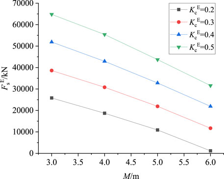
Figure 13. Variation law of FsE with the mining thickness M of the coal seam.
In summary, as the WF enters the CP, the ISR increases with rising SCF KcE, main roof weighting interval, and fracture position distance and decreases with SCF KmE and mining thickness M.
3.2 Mechanical analysis of the seesaw when the WF exits the CP
Figure 14 illustrates the model of the main roof breaking “seesaw” when the WF exits the CP. As depicted, the main fulcrum is situated in the coal wall, with the WF’s hydraulic support serving as the auxiliary point. Notably, the mechanical distinctions between the “seesaw” when the WF exits the CP and when it enters the CP are evident in the following two aspects:
(1) The SCF (KcO >1) at the goaf substantially exceeds the SCF KcE <1 at the CP. This disparity arises because, upon CP removal, the “seesaw” area lies directly beneath the stress concentration zone at the CP’s edge. Consequently, the greater the load Qb of the “seesaw” above the goaf, the easier it rotates toward the goaf.
(2) During CP exit, the inner part of the coal wall in front of the “seesaw” resides below the upper goaf (i.e., the stress reduction area). Consequently, the SCF of the leading abutment pressure in the coal wall of the WF (KmO <1) and the resultant force QmE of the front abutment pressure are diminished, facilitating the “seesaw’s” rotation toward the goaf.
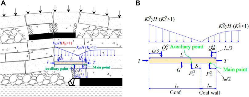
Figure 14. Force analysis of the seesaw when the WF exits the CP: (A) stress distribution of the overlying strata in the WF exiting the CP stage; (B) roof mechanical model analysis.
Under the combined effect of these factors, the fundamental “seesaw” structure is more prone to rotate toward the goaf during CP exit than during CP entry. Therefore, the support merely needs to offer a larger supporting force to prevent the “seesaw” from rotating. This leads to significant safety valve opening, top subsidence cutting, and heightened coal wall ore pressure due to the WF’s hydraulic thrust.
According to the force analysis of the “seesaw” during the CP exit, the equilibrium equation can be formulated as follows:
In these formulas, KcO represents the SCF of the hanging side of the seesaw, while KmO denotes the SCF of the abutment pressure of the seesaw in the coal wall.
According to Formulas 6, 7, the supporting force Fs can be calculated as follows:
By substituting Formula 8 into Formula 9, we get the following equation:
The main roof thickness and mechanical parameters, the seam thickness and mechanical parameters, and the burial depth remain constant during WF passage through the CP, implying that the periodic weighting interval and fracture position in the coal wall remain unchanged.
Combining Equations 5 and 10 yields the hydraulic support force ratio when the WF exits and enters the CP, which is as follows:
According to Formula 11, when the WF exits the CP and enters the CP, the SCF is influenced by the SCF (KcE, KcO) on the hanging side of the seesaw and the SCF (KmE, KmO) of the abutment pressure of the seesaw in the coal wall.
The SCF above the goaf is KcO ˃1, while the inner part of the coal wall in front of the goaf resides in the stress reduction area below the goaf. Consequently, the SCF of the leading abutment pressure in the coal wall of the WF is KmO˂1.
Conversely, when the CP is inserted into the WF, the stress on the “seesaw” behind the WF presents the opposite scenario: KcE˂1 above the goaf and KmE˃1 for the leading abutment pressure in the coal wall of the WF.
According to Formula 11, the ratio FsO/FsE >1 of the supporting force indicates that the load of the support when exiting the CP in the WF is significantly greater than when entering the CP. Consequently, the “seesaw” is more likely to rotate toward the goaf when the WF exits the CP, resulting in intensified ground pressure.
3.3 Construction of the roof structure model for the WF passing through the CP
Figure 15 illustrates the activity of the surrounding rock and the vertical stress distribution (where the blue line represents the vertical stress of the key stratum) in the interlayer sub-key stratum 1 as the WF advances to different positions. Upon entering the CP boundary, the WF and the front coal wall jointly support the load of the upper rock layer, which is primarily borne by the front coal body (Figure 15B).
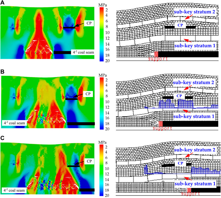
Figure 15. Strata structure and sub-key stratum 1 stress distribution of the 4–2 coal seam under pillar mining: (A) before entering the CP; (B) when entering the CP; (C) when exiting the CP.
As the WF approaches the boundary of the CP, a significant load is transmitted below the right boundary of the CP. Upon exiting the boundary, the support aligns directly beneath the overlying CP boundary, influenced by the fracture interval of the sub-key stratum 1 (Figure 15C). During this phase, the load on the stope’s surrounding rock concentrates directly above the support. Consequently, when the WF exits the CP boundary, the coal body ahead of the WF remains unloaded, with the main load concentrated on the support. This creates a lever-like fulcrum at the support position, making the WF susceptible to considerable ground pressure and even crushing disasters upon pushing beyond the boundary. Following the occurrence of dynamic load rock pressure in the CP stage, the stress distribution of survey line 2 in the sub-key layer 1 is re-transferred to the coal body in front of the WF.
Figure 16 illustrates the change in the supporting stress curve inside the CP as the WF advances through different mining stages. Due to the CP’s width of 36 m, the stress inside the CP after WF mining presents a double hump type (Figure 16A). During the period when the WF enters the CP boundary, the load inside the CP undergoes slight changes with minimal alterations in the hump distribution characteristics on the CP’s right side (Figure 16B). Upon exiting the CP boundary, the stress on the CP’s right side sharply declines, as depicted in Figure 16C.
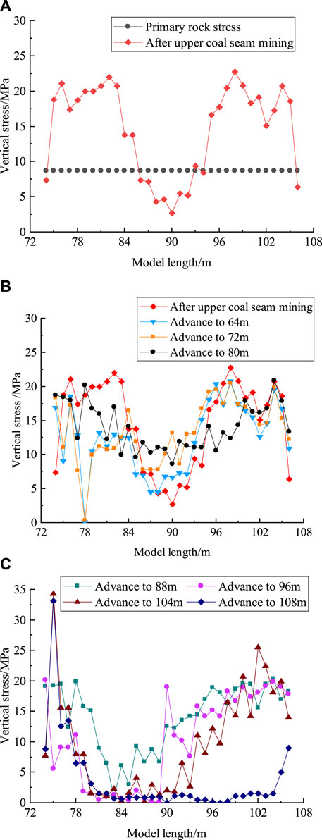
Figure 16. Abutment pressure distribution in the CPs during the upper and lower coal-seam mining: (A) after the mining of the upper coal seam; (B) during entry into the CP; (C) during exit from the CP.
Figure 17 depicts the stress distribution curve in the sub-key layer 1 between the layers as the WF enters and leaves the CP boundary. When the WF enters the CP, the load of the overlying strata is shared by the support and the front coal body (Figure 17A). As the WF exits the CP, the bearing fulcrum gradually shifts toward the WF until it acts on the support. Subsequently, after the WF exits the CP boundary, the load of the overlying strata is transferred back to the coal wall of the WF.
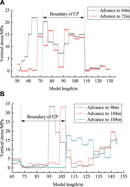
Figure 17. Stress evolution in sub-key stratum 1: (A) during entry into the CP; (B) during exit from the CP.
Numerical simulation revealed that the transfer of the roof structure’s fulcrum varies as the WF enters and exits the CP boundary. This observation confirms the accuracy of the seesaw mechanical model.
4 Discussions
Based on the fundamental physical and mechanical parameters in the Buertai Mine and the support parameters, the variation in the support force ratio with various parameters can be determined by combining Formula 11 when the working face exits and enters the CP.
4.1 Variation law of SCF KcO
The support force ratio changes with SCF KcO on the hanging side of the seesaw when the WF exits and enters the CP, as illustrated in Figure 18. With an increase in the side SCF of the gob of the “seesaw” during CP discharge, the support force ratio during CP operation gradually increases. For instance, when the SCF of the gob of the “seesaw” during CP discharge is KcE = 0.5, 0.6, 0.7, and 0.8, respectively, the support force of the support is approximately 12 times, 9 times, 7 times, and 6 times that of the support during CP discharge.
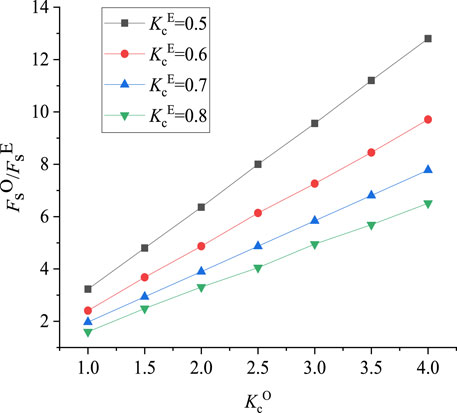
Figure 18. Support force ratio with the variation in SCF KcO on the hanging side of the seesaw.
4.2 Variation in KmO of front abutment pressure in the coal wall
The support force ratio changes with SCF KmO of the stilted slab, as depicted in Figure 19. For SCF values in the gob of KcO = 2, 3, 4, and 5, the pressure is approximately 6 times, 9 times, 13 times, and 16 times that of the CP. The SCF KmO of the “seesaw” has no significant influence on the pressure of the support on the WF.
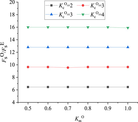
Figure 19. Variation in the ratio of support force with SCF KmO within the warped coal wall.
4.3 Variation in the support force ratio with the fracture position lm
The support force ratio varies with the fracture position lm of the seesaw, as shown in Figure 20. The fracture position of the “seesaw” in the coal wall has minimal influence on the pressure. For SCFs in the gob of KcO = 2, 3, 4, and 5, the pressure of the support is approximately 4 times, 6 times, 7 times, and 9 times that of the CP, respectively.

Figure 20. Support force ratio with the change law of the fracture position of the seesaw.
The support force ratio when the WF exits and enters the CP is primarily affected by the SCF (KcE, KcO) of the hanging side of the seesaw and the abutment pressure SCF (KmE, KmO) of the seesaw in the coal wall. The SCF KcO>1 of the “seesaw” above the goaf when the WF exits the CP and the inner part of the coal wall in front of the “seesaw” is located in the stress reduction zone below the goaf, indicating that the SCF KmO<1 of the leading abutment pressure in the coal wall of the WF.
However, when the WF enters the CP, the stress situation behind the “qiao slab” in front of the WF is reversed, with SCF KcE<1 above the goaf and SCF KmE>1 of the leading abutment pressure in the coal wall of the WF.
According to Formula 11, the ratio FsO/FsE >1 of the supporting force when the WF exits and enters the CP, which indicates that the load of the hydraulic support when the WF enters the CP is significantly greater than that when the WF exits the CP. This implies that the “seesaw” is more likely to turn toward the goaf when the CP is discharged, leading to more intense ore pressure on the WF.
5 Engineering practice and the effect of hydraulic fracturing
In the 42108 WF, a total of six drilling fields are arranged, each containing three boreholes, resulting in a total of 18 boreholes. The designed aperture is 96 mm, with the No.1 hole extending 96 mm to the immediate roof, the No. 2 hole extending 153 mm, and the lower 127-mm casing crossing the rock stratum for 10 m. Following casing solidification, a 96-mm final hole is drilled according to the design trajectory. The target layer for borehole fracturing is the main roof sandstone. Individual hole lengths range from 350 m to 585 m, with each hole designed to fracture into 5 to 10 sections. The cumulative drilling length is 8320 m, with a total of 140 designed fracturing sections. Among these, the No. 1 drilling field addresses the initial mining and cutting position of the WF; the No.2 to No.3 drilling fields correspond to the square position of the WF, while the No. 4 to No. 6 drilling fields are situated in areas deeper than 400 m. Given a WF width of 313 m, boreholes are evenly distributed with a spacing of 78.25 m, extending from the 42108 WF auxiliary head gate and head gate. When fracturing a single borehole at an adjacent position, the spacing between the two boreholes is maintained within 30 m; when both boreholes require fracturing, the spacing is within 60 m. The preliminary design sets the fracturing section spacing at 30 m, with a fracturing section length of 6 m.
In this engineering endeavor, the multi-point drag staged hydraulic fracturing method of roof directional long boreholes is employed, with clear water chosen as the fracturing medium. The pump group initiates pump operation at a low position. Once the pressure exceeds 5 MPa, the packer completes expansion and setting. Hydraulic fracturing construction proceeds via simultaneous double pump activation. The injection flow rate increases, rapidly elevating pressure to 30.7 MPa. High-pressure water flow then acts on the coal wall, initiating construction. Subsequently, the fracturing equipment undergoes a cycle of drainage and dragging to the designated fracturing section. The drilling length totals 408 m, with nine cumulative fracturing sections. Each fracturing section spans 6.4 m, with continuous water injection fracturing lasting 1,068 min. The cumulative water injection volume amounts to 410.35 m3, with the maximum pressure reaching 30.7 MPa, minimum pressure at 10.0 MPa, maximum pressure drop of 10.0 MPa, and more than 200 instances of cumulative pressure drops exceeding 3.0 MPa. The fracturing effect is evident.
Figure 21 illustrates that under identical geological mining conditions, the maximum load borne by the supports of WF 42107 and 42108 is lower than that of WF 42106. Specifically, the maximum load of WF supports with directional long borehole staged hydraulic fracturing is lower compared to that of WF supports without hydraulic fracturing. During the initial mining phase, the average maximum load of WF 42106 support is 42.80 MPa, whereas that of WF 42107 is 38.95 MPa, and that of WF 42108 is 36.14 MPa. Consequently, the maximum load of WF 42107 is 3.85 MPa lower than that of WF 42106 support, marking a decrease of 15.56%. Similarly, the maximum load of WF 42108 is 6.66 MPa lower than that of WF 42106 support, indicating a decrease of 8.97%.
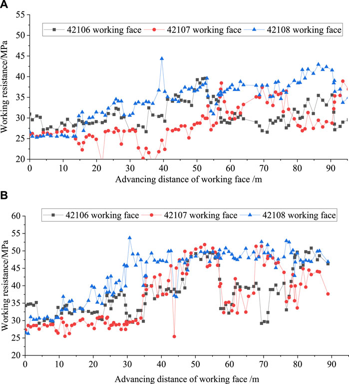
Figure 21. Comparison of the load of the support during the initial mining stage: (A) average load of the support; (B) maximum load of the support.
Field measurements and analysis reveal that following the implementation of hydraulic fracturing in WFs 42107 and 42108, compared with WF 42106 without hydraulic fracturing, several improvements are noted. The continuous distance of the first weighting of the main roof is reduced, resulting in an average pressure decrease of 7.8 MPa during the initial weighting of the main roof. Moreover, the dynamic load coefficient decreases by 17% to 1.48. This reduction is attributed to a decrease in the initial pressure range and the area of the main roof, with the pressure area reduced to 4083.9 km2, which is nearly three times smaller, as depicted in Table 3.
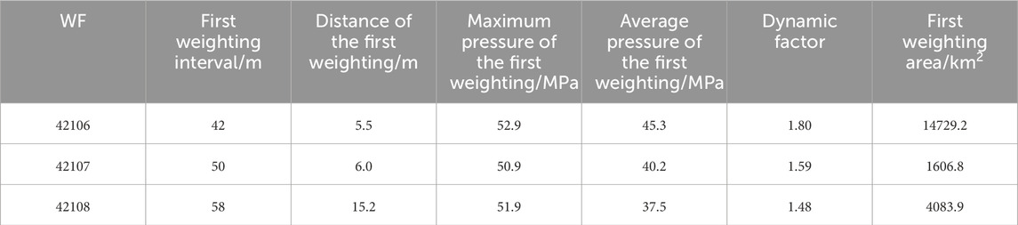
Table 3. Comparison of mine pressure parameters in WF.
6 Conclusion
(1) This study analyzed the mechanism of strong mine pressure in the CP-affected area. When the WF traversed the parallel CP, the hard roof of the interburden fractured and collapsed, forming a masonry beam structure. Drawing from the O–X fracture characteristics of the broken roof strata in the WF, we constructed a seesaw structure model depicting the overburden formation when the WF passed through the CP.
(2) Theoretical analysis revealed that as the WF entered the CP area, the stress concentration of the CP caused the SCF of the hard roof to exceed 1, while behind the WF, it decreased below 1. When the support resistance of the WF was moderate, it prevented violent rotation of the fan-shaped seesaw, averting support-crushing accidents. Conversely, upon exiting the CP area, the stress concentration of the CP significantly elevated the SCF of the hard roof. This may induce shear failure in the main roof, rendering the coal wall incapable of supporting it, leading to roof-cutting subsidence and intensified ground pressure, thus increasing the likelihood of support-crushing accidents.
(3) Numerical calculations revealed a notable stress escalation in the parallel CP following the mining of the upper coal seam, coupled with severe plastic damage to the interburden. Subsequent mining of the lower coal seam exacerbated the plastic failure degree of the overlying parallel CP, significantly impacting the stress and displacement of the surrounding rock of the WF in the lower coal seam.
(4) We established a comprehensive control technology for mitigating strong ground pressure through hydraulic fracturing to weaken the hard roof. Technical parameters defining hydraulic fracturing to weaken the hard roof were delineated. Through the implementation of strong ground pressure control in WF and monitoring of ground pressure, effective mitigation of the detrimental effects of the overlying CP on strong ground pressure during lower coal-seam mining was achieved.
Data availability statement
The original contributions presented in the study are included in the article/supplementary material; further inquiries can be directed to the corresponding authors.
Author contributions
HZ: data curation, formal analysis, investigation, methodology, project administration, resources, software, supervision, visualization, writing–original draft, and writing–review and editing. QH: data curation, formal analysis, funding acquisition, investigation, methodology, project administration, supervision, validation, visualization, writing–original draft, and writing–review and editing. YH: conceptualization, data curation, funding acquisition, methodology, project administration, resources, writing–original draft, and writing–review and editing. QW: conceptualization, data curation, investigation, methodology, resources, and writing–original draft. YW: conceptualization, data curation, formal analysis, and writing–original draft.
Funding
The authors declare financial support was received for the research, authorship, and/or publication of this article. This research was funded by the National Natural Science Foundation of China, grant numbers 52074211 and 52304153.
Acknowledgments
The authors thank the National Natural Science Foundation of China for its support of this study. They thank the academic editors and reviewers for their kind suggestions and valuable comments.
Conflict of interest
Authors HZ and QW were employed by China Energy Shandong Coal Group Co., Ltd.
The remaining authors declare that the research was conducted in the absence of any commercial or financial relationships that could be construed as a potential conflict of interest.
Publisher’s note
All claims expressed in this article are solely those of the authors and do not necessarily represent those of their affiliated organizations, or those of the publisher, the editors, and the reviewers. Any product that may be evaluated in this article, or claim that may be made by its manufacturer, is not guaranteed or endorsed by the publisher.
References
Bai, J. W., Cui, B. Q., Q, T. Y., Zhu, W. B., Wang, K., Shi, X. D., et al. (2021). Fundamental theory for rock strata control of key pillar-side backfilling. Int. J. Coal Sci. Techno. 46, 424–438. doi:10.13225/j.cnki.jccs.XR20.1869
Bai, Q., Tu, S., Wang, F., and Zhang, C. (2017). Field and numerical investigations of gateroad system failure induced by hard roofs in a longwall top coal caving face. Int. J. Coal Geol. 173, 176–199. doi:10.1016/j.coal.2017.02.015
Cao, Z. Z., Sun, Q., Li, Z. H., and Du, F. (2024). Abnormal ore pressure mechanism of working face under the influence of overlying concentrated coal pillar. Sci. Rep. 14 (1), 626. doi:10.1038/s41598-024-51148-x
Chen, B. B., Liu, C. Y., and Wang, B. (2022). A case study of the periodic fracture control of a thick-hard roof based on deep-hole pre-splitting blasting. Energ. explor. Exploit. 40, 279–301. doi:10.1177/01445987211036245
Cheng, S., Ma, Z., Gong, P., Li, K. L., Li, N., and Wang, T. (2020). Controlling the deformation of a small coal pillar retaining roadway by non-penetrating directional pre-splitting blasting with a deep hole: a case study in Wangzhuang Coal Mine. Energies 13 (12), 3084. doi:10.3390/en13123084
Dai, J., Shan, P., and Zhou, Q. (2020). Study on intelligent identification method of coal pillar stability in fully mechanized caving face of thick coal seam. Energies 13 (2), 305. doi:10.3390/en13020305
Dang, J. X., Tu, M., Zhang, X. Y., and Bu, Q. W. (2024). Research on the bearing characteristics of brackets in thick hard roof mining sites and the effect of blasting on roof control. Geomech. Geophys. Geo. 10, 18. doi:10.1007/s40948-024-00735-3
Du, J. T. (2019). Size Optimization of narrow coal pillar in fully mechanized caving face under short distance goaf. Coal Eng. 51, 11–14.
Fang, Z. Y., Liu, L., Zhang, X. Y., Han, K. M., Wang, L. Y., Zhu, M. B., et al. (2023). Carbonation Curing of Modified Magnesium-Coal Based Solid Waste Backfill Material for CO2 Sequestration. Process Safety and Environmental Protection 180, 778–788. doi:10.1016/j.psep.2023.10.049
Feng, G. D., Zhu, W. B., Li, Z., Bai, J. W., and Luo, Z. Q. (2022). Dynamic collapse mechanism and prevention of shallow-buried pillar group underlying working seam floor in mined-out area. Int. J. Coal Sci. Techno. 47, 200–209. doi:10.13225/j.cnki.jccs.2020.1864
Gao, R., Yu, B., and Meng, X. B. (2018). Study on the mechanism of strong strata behavior influenced by overlying coal pillar and control technology of ground fracturing. J. Min. Saf. Eng. 35, 324–331. doi:10.13545/j.cnki.jmse.2018.02.013
He, J., Dou, L. M., Mu, Z. L., and Gong, S. Y. (2016). Numerical simulation study on hard-thick roof inducing rock burst in coal mine. J. Cent. South Uni 23, 2314–2320. doi:10.1007/s11771-016-3289-4
He, Y. P., Lv, W. Y., Fang, Z. Y., Ma, L., and Cong, C. K. (2024). The basic characteristics of paste backfill materials based on highly active mineral admixtures: Part I. Preliminary study on flow, mechanics, hydration and microscopic properties. Process Safety and Environmental Protection. doi:10.1016/j.psep.2024.05.056
Huang, B. X., Zhao, X. L., Chen, S. L., and Liu, J. W. (2017). Theory and technology of controlling hard roof with hydraulic fracturing in underground mining. Chin. J. Rock Mech. Eng. 36, 2954–2970. doi:10.13722/j.cnki.jrme.2017.0078
Huang, Q. X., and He, Y. P. (2019). Research on overburden movement characteristics of large mining height working face in shallow buried thin bedrock. Energies 12, 4208. doi:10.3390/en12214208
Huang, Q. X., He, Y. P., and Cao, J. (2019a). Experimental investigation on crack development characteristics in shallow coal seam mining in China. Energies 12, 1302. doi:10.3390/en12071302
Huang, Q. X., Zhao, M. Y., and Huang, K. J. (2019b). Study of roof double key strata structure and support resistance of shallow coal seams group mining. Int. J. Min. Sci. Technol. 48, 71–77+86. doi:10.13247/j.cnki.jcumt.000968
Jia, S. W., Fan, Z. G., Song, Z. G., and Lou, T. (2020). Floor stress analysis and mining roadway reasonable layout under residual coal pillar floor in lower seam of continuous coal seams. Coal Eng. 52, 11–15.
Jiang, B., Ma, F. L., Wang, Q., Gao, H. K., Zhai, D. H., Deng, Y. S., et al. (2024). Drilling-based measuring method for the c-φ parameter of rock and its field application. Int. J. Min. Sci. Technol. 34 (1), 65–76. doi:10.1016/j.ijmst.2023.06.005
Jiang, W., Ju, W. J., Wang, Z. L., Zhang, Z., and Shi, M. (2020). Characteristics of overburden stress distribution and rational pillar width determination of gob-side roadway with thick and hard main roof in fully mechanized top coal caving workface. J. Min. Saf. 37, 1142–1151. doi:10.13545/j.cnki.jmse.2020.02.012
Kang, H. P., Xu, G., Wang, B. M., Wu, Y. Z., Jiang, P. F., Pan, J. F., et al. (2019). Forty years development and prospects of underground coal mining and strata control technologies in China. J. Min. Strata Control Eng. 1, 7–39.
Kong, L. (2020). Overlying strata movement law and its strata pressure mechanism in fully mechanized top-coal caving workface with large space. J. Min. Saf. Eng. 37, 943–950. doi:10.13545/j.cnki.jmse.2020.05.010
Li, G., Zhu, C., Tang, S. B., Dun, K., and Wu, C. Z. (2023c). Energy balance support method in soft rock tunnel with energy absorbing anchor cable. Tunn. Undergr. Sp. Tech. 141, 105380. doi:10.1016/j.tust.2023.105380
Li, J. W., Fu, B. J., Zhang, H. L., Zhao, Q. C., and Bu, Q. W. (2023a). Study on fracture behavior of directly covered thick hard roof based on bearing capacity of supports. Appl. Sci.Basel. 13, 2546. doi:10.3390/app13042546
Li, X. S., Li, Q. H., Wang, Y. M., Liu, W., Hou, D., Zheng, W. B., et al. (2023b). Experimental study on instability mechanism and critical intensity of rainfall of high-steep rock slopes under unsaturated conditions. Int. J. Min. Sci. Technol. 33 (10), 1243–1260. doi:10.1016/j.ijmst.2023.07.009
Li, Y., Tai, Y., Yu, B., Kuang, T. J., Gao, R., and Liu, J. Y. (2024). Evolution and control technology of energy aggregation and dissipation of a high hard roof during breakage and destabilization. Int. J. Fract. 245, 1–23. doi:10.1007/s10704-023-00745-4
Li, Z. H., Yang, K., Hua, X. Z., Li, Y. F., and Liu, Q. J. (2020). Disaster-causing mechanism of instability and “macroscopic-big small” structures of overlying strata in longwall mining. Int. J. Coal Sci. Techno. 45, 541–550.
Maleki, H. (2017). Coal pillar mechanics of violent failure in U.S. Mines. Int. J. Min. Sci. Technol. 27, 387–392. doi:10.1016/j.ijmst.2017.03.001
Qin, D. D., Chang, Z. C., and Xia, Z. (2024). Experiment study on the mechanical behavior and acoustic emission response of thick and hard sandstone roof in Xinjiang Mining Area. Adv. Civ. Eng., 6205478.
Ren, F. Q., Zhu, C., Yuan, Z. H., Karakus, M., Tang, S. B., and He, M. (2023). Recognition of shear and tension signals based on acoustic emission parameters and waveform using machine learning methods. Int. J. Rock. Min. Sci. 171, 105578. doi:10.1016/j.ijrmms.2023.105578
Shi, H., Chen, W., Zhang, H., and Song, L. (2023b). A novel obtaining method and mesoscopic mechanism of pseudo-shear strength parameter evolution of sandstone. Environ. Earth Sci. 82, 60. doi:10.1007/s12665-023-10748-y
Shi, H., Chen, W. L., Zhang, H. Q., Song, L., Li, M., Wang, M. J., et al. (2023a). Dynamic strength characteristics of fractured rock mass. Eng. Fract. Mech. 292, 109678. doi:10.1016/j.engfracmech.2023.109678
Song, X. M., Zhu, D. F., Wang, Z. L., Huo, Y. M., Liu, Y. Y., Liu, G. F., et al. (2021). Advances on longwall fully-mechanized top-coal caving mining technology in China during past 40 years: theory,equipment and approach. Coal Sci. Technol. 49, 1–29.
Tang, S. B., Wang, J. X., Teng, L. X., and Ding, S. (2024). Automatic early warning of rock bursts from microseismic events by learning the feature-augmented point cloud representation. Tunn. Undergr. Sp. Tech. 147, 105692. doi:10.1016/j.tust.2024.105692
Wang, H. W., Jiao, J. Q., Wu, Y. P., Zheng, K. G., Li, Y. J., Wang, T., et al. (2023). Deformation characteristics and stress evolution law of composite hard roof under presplitting weakening. Min. Metall. Explor. 40, 839–850. doi:10.1007/s42461-023-00775-5
Wang, Z. Q., Shi, L., Wu, C., Lv, W. Y., Sun, Z. W., Luo, J. Q., et al. (2021). Classification of co-mining types and stability analysisof interlayer in extremely close coal seams. J. Min. Saf. Eng. 38, 458–468+478. doi:10.13545/j.cnki.jmse.2020.0533
Wu, J., Wong, H. S., Yin, Q., and Ma, D. (2023). Effects of aggregate strength and mass fraction on mesoscopic fracture characteristics of cemented rockfill from gangue as recycled aggregate. Compos. Struct. 311, 116851. doi:10.1016/j.compstruct.2023.116851
Wu, J., Wong, H. S., Zhang, H., Yin, Q., Jing, H., and Ma, D. (2024). Improvement of cemented rockfill by premixing low-alkalinity activator and fly ash for recycling gangue and partially replacing cement. Cem. Concr. Compos. 145, 105345. doi:10.1016/j.cemconcomp.2023.105345
Wu, S. C., Zhang, S. H., and Zhang, G. (2018). Three-dimensional strength estimation of intact rocks using a modified Hoek-Brown criterion based on a new deviatoric function. Int. J. Rock. Mech. Min.Sci. 107, 181–190. doi:10.1016/j.ijrmms.2018.04.050
Xu, Q. Y., Huang, Q. G., and Zhang, G. C. (2019). Fracture and instability mechanism and control technology of a narrow coal pillar in an entry in fully mechanized caving mining under intense effect mining. J. Min. Saf. 36, 941–948.
Xue, J. S., Zhao, T. L., and Pan, L. M. (2021). Research on characteristics of underground pressure behavior of extra-thick coal seams in “High-Low” thick and hard rock layers in fully mechanized caving working face. Coal Technol. 40, 55–59.
Yang, J. X., Liu, C. Y., Yu, B., and Wu, F. F. (2016). An analysis on strong strata behaviors and stress transfer of the roadway approaching gob in triangle area of the face end. J. Min. Saf. Eng. 33, 88–95. doi:10.13545/j.cnki.jmse.2016.01.014
Yin, Q., Wu, J. Y., Zhu, C., He, M. C., Meng, Q. X., and Jing, H. W. (2021). Shear mechanical responses of sandstone exposed to high temperature under constant normal stiffness boundary conditions. Geomech. Geophys. Geo. 7 (2), 35–17. doi:10.1007/s40948-021-00234-9
Yu, B. (2010). Study on fully mechanized coal mining technology in passed 40 years in Datong mining area. Int. J. Coal Sci. Techno. 35, 1772–1777.
Zhang, G. C., Wu, T., Wu, J. L., Dai, D. S., Shen, S. B., and Zhao, R. B. (2019). Mechanism and control technology of top coal squeezing and fracture of gob-side entry driving in fully-mechanized caving mining face. Coal Sci. Technol. 47, 95–100.
Zheng, Q. Q., Qian, J. W., Zhang, H. J., Chen, Y. K., and Zhang, S. H. (2024). Velocity tomography of cross-sectional damage evolution along rock longitudinal direction under uniaxial loading. Tunn. Undergr. Sp. Tech. 143, 105503. doi:10.1016/j.tust.2023.105503
Zheng, S. S., and Kong, D. Z. (2020). Fracture characteristics of hard roof and overlying rock movement in working face. Coal Eng. 52, 11–15.
Zhu, W. B., Xu, J. L., Chen, L., Li, Z., and Liu, W. T. (2019). Mechanism of disaster induced by dynamic instability of coal pillar group in room-and-pillar mining of shallow and close coal seams. Int. J. Coal Sci. Techno. 44, 358–366. doi:10.13225/j.cnki.jccs.2018.0907
Zhu, W. B., and Yu, B. (2018). Breakage form and its effect on strata behavior of far field key stratum inlarge space stope. Coal Sci. Technol. 46, 99–104.
Keywords: parallel coal pillar, hard roof, strong ground pressure, fan-shaped seesaw, hydraulic fracturing
Citation: Zhou H, Huang Q, He Y, Wang Q and Wei Y (2024) A study on the mechanism and control technology of strong mine pressure in parallel coal pillar and hard roof mining. Front. Earth Sci. 12:1407084. doi: 10.3389/feart.2024.1407084
Received: 26 March 2024; Accepted: 02 May 2024;
Published: 31 May 2024.
Edited by:
Hao Shi, Anhui University of Science and Technology, ChinaReviewed by:
Qiangqiang Zheng, University of Science and Technology of China, ChinaGuang Zhang, Information Institute of the Ministry of Emergency Management, China
Copyright © 2024 Zhou, Huang, He, Wang and Wei. This is an open-access article distributed under the terms of the Creative Commons Attribution License (CC BY). The use, distribution or reproduction in other forums is permitted, provided the original author(s) and the copyright owner(s) are credited and that the original publication in this journal is cited, in accordance with accepted academic practice. No use, distribution or reproduction is permitted which does not comply with these terms.
*Correspondence: Qingxiang Huang, aHVhbmdxeEB4dXN0LnNuLmNu; Yanpeng He, aGV5cEB4dXN0LmVkdS5jbg==