 Jue Wang
 Genbo Peng2
 Ziyuan Cong
94% of researchers rate our articles as excellent or good
Learn more about the work of our research integrity team to safeguard the quality of each article we publish.
Find out more
ORIGINAL RESEARCH article
Front. Earth Sci., 10 April 2024
Sec. Geochemistry
Volume 12 - 2024 | https://doi.org/10.3389/feart.2024.1394491
This article is part of the Research TopicUnconventional Resources: Provenance Analysis, Sediment Transport, Reservoir Evaluation, Geo-energyView all 29 articles
Multi-cluster hydraulic fracturing of horizontal wells is a well-adopted technique with high efficiency to increase the production of tight and shale formations. However, the stress shadows among clusters pose challenges to the synchronous propagation of hydraulic fractures during multi-cluster fracturing. In order to explore the fracture propagation mechanism and characteristics under the influence of stress shadow in low-spacing staged multi-cluster fracturing, a three-dimensional hydraulic fracturing model was generated using a lattice-based method. This model considered the impact of geological and engineering parameters on the propagation behavior of multiple fractures in shale formation. A variable pumping approach is adopted, where the fracturing fluid is initially injected at a high rate and then transitioned to a lower rate. Afterward, a method was proposed to quantitatively assess the extent of fracturing in a specific area (i.e., the stimulated area), considering the impact of stress shadow within a single stage. The simulation results demonstrated significant differences in the fracture stimulation area due to the influence of each parameter in the case of uncontrollable geological factors and controllable engineering factors. An increase in both Young’s modulus and stress anisotropy of the reservoir results led to a corresponding increase in the total fracture stimulation area. As the principal stress orientation increased, the fracture stimulation area gradually decreased. In terms of operational parameters, the stimulated area of hydraulic fractures gradually decreased as the fracture spacing increased. With increasing injection rate, the stimulated area initially expanded and then decreased, peaking at an injection rate of 0.04 m3/s. These findings can provide valuable insights into the propagation behavior of multi-cluster hydraulic fractures under uncertain parameters, with significant implications for future engineering applications.
Shale and tight reservoirs are preferred for the exploration and development of unconventional oil and gas resources. In order to increase production, horizontal wellbores with multi-cluster hydraulic fracturing need to be widely adopted. As the key factor affecting horizontal well multi-cluster fracturing technology, fracture stress interference has been emphasized in several studies. Nevertheless, an inadequate quantitative understanding of the impact of fracture stress shadows between fractures results in a weak foundation for designing fracture cluster spacing.
Numerous studies have been conducted on stress shadow during the propagation of multiple hydraulic fracturing (Geyer and Nemat-Nasser, 1982; Pollard and Aydin, 1988; Abass et al., 1996; Olson and Dahi-Taleghani, 2009; Bunger et al., 2011; Miller et al., 2011; Xing et al., 2018; Cong et al., 2022; Zhang et al., 2022; Li et al., 2023a). Bunger et al. (2011) investigated the effect of fracture initiation sequence on the deflection angle during fracture propagation through laboratory model experiments. These short fractures were deflected due to stress interference caused by long fractures. Zheng et al. (2020) explored the fracture extension in sandstone specimens under true triaxial stress conditions, considering both simultaneous and sequential fracturing. The experimental results showed that the distribution of fractures exhibited asymmetry due to the influence of pore pressure and stress field factors. Zhou et al. (2018) improved the pumping system to fracture large shale samples. The initiation and propagation of single fractures were observed in most cases. In addition to inhibiting the propagation of adjacent fractures, the stress shadow effect between fractures also causes the branching of adjacent fractures (Sani et al., 2015; Ugueto et al., 2016; Fu et al., 2019; Xiao and Xiao, 2019; Xie et al., 2019; Cong et al., 2021; Tian et al., 2022; Li et al., 2023b). The fracture initiation sequence can change the original stress field of the formation and generate stress shadows, thus influencing the morphology of the subsequent fractures. In contrast, the pumping mode can alleviate the effect of stress shadow to some extent. However, physical experiments can only provide qualitative insights into fracture propagation and are subject to several restrictions, including complex experimental preparation, high costs, lab sample scale effects, and monitoring tools.
A series of numerical methods and models have been proposed to explore the effects of stress shadows and complex stress fields on fracture propagation (Bakhshi et al., 2019; Zhang et al., 2024). Current research primarily focuses on geological conditions and operational means. Sheng et al. (2018) analyzed the interaction between different fractures by simulating the five-stage hydraulic fracturing treatment using the extended finite element method. The results showed that the fracture deflection increased with decreasing fracture spacing and stress difference, and the fracture deflection was insensitive to the increase of Young’s modulus. Based on the extended finite element method, Wang et al. (2018) investigated the effect of pre-existing fractures on the initiation and expansion of the subsequent fracture using the cohesion unit. The results showed that the propped width of the previous fracture, the fracture spacing, and Young’s modulus of the reservoir were the main factors in controlling the injection pressure of the subsequent fracture. Liu et al. (2020) studied shale multi-cluster hydraulic fracturing using XSite software based on a particle-based simulation calculation method. The results showed significant effects of stress anisotropy and cluster spacing on the geometry of the extended fracture. Multi-cluster fractures exhibit varying extension conditions in different geological settings. Previous scholars have conducted several studies on the effects of operational engineering parameters to enhance the uniform extension of multi-cluster fractures. Han et al. (2020) investigated the fracture extension paths under neighboring perforations at different injection rates by extended finite elements. The simulation results suggested that a closer increment of the injection rate of neighboring perforations increases the stress-shadow area between the fractures. Duan et al. (2020) investigated the evolutionary characteristics of simultaneously induced fractures using a discrete element method. The effects of field stress and engineering parameters on fracture morphology were also explored. The results showed that the higher effective stress anisotropy counteracted the stress-shadow effect, forcing the fractures to propagate in the direction of maximum stress and forming relatively long parallel fractures. Increasing the spacing can alleviate the stress-shadow effect, while the effects of injection rate and fluid viscosity on middle fracture interactions are not significant (Yamamoto et al., 2004; Kumar and Ghassemi, 2006; Lecampion, 2008; Ooi et al., 2012; Wu et al., 2012; Dohmen et al., 2014; Sobhaniaragh et al., 2018). Researchers have conducted numerous studies on geological and engineering parameters. However, the fracturing effect has only been studied from the viewpoint of a single factor. In reality, hydraulic fracturing with multiple clusters of fracture extensions is the outcome of the combined effects of various engineering parameters under specific formation conditions. Hence, this study examines the impact of geological factors on fracture extension and proposes a method to enhance multi-cluster fracture extension. It involves optimizing the spacing of fracture clusters, injection rate, and pumping method based on controllable engineering parameters corresponding to the specific geological conditions of the reservoir. Since operational parameters and geological properties are key factors affecting the interactions between fractures, it is necessary to comprehensively investigate the effects of these parameters on the shape and geometry of fractures.
In this work, a three-dimensional model is constructed using hydraulic fracturing software based on the discrete lattice theory and synthetic rock mass method. The effect of a relatively short cluster spacing (5 m or less) on fracture propagation behavior was investigated through a series of case studies, considering operational parameters (injection rate, the number of fractures) and reservoir parameters (reservoir Young’s modulus, stress anisotropy, principal stress direction). The findings can provide valuable theoretical insights for the fracturing spacing design in horizontal shale wells.
The XSite lattice simulator developed by the Itasca Consulting Group is employed to simulate the propagation of hydraulic fracture using the discrete element method (DEM) and synthetic rock mass (SRM) (Damjanac and Cundal, 2016; Xing et al., 2018). This advanced simulator allows for dynamic simulation of the fracturing process without predefining the propagation path. The smooth joint model (SJM) represents pre-existing joints in the simulator, while the lattice effectively simulates fracture propagation in rock materials.
The lattice nodes are connected by normal and shear springs and randomly distributed within the simulator to accurately simulate the behavior of rock masses. In order to replicate the translational motion of each node, a precise central difference equation for the linear momentum equilibrium and displacement-velocity relationships was adopted in Eqs 1, 2 (Damjanac and Cundal, 2016):
where
where
where N denotes “Normal”; S denotes “shear”;
The following equations show the correlation between the micro spring and the macro rock mass in terms of tensile strength and shear strength in Eqs 6, 7:
where FNmax represents the spring tensile strength; FSmax denotes the spring shear strength;
Fluid flow is simulated within the intact rock matrix and the joints, where the flow in the fractures can be resolved through a network of fluid nodes connected by pipes. Additionally, the matrix flow representing the leakage to the intact rock is considered, which is dependent on the permeability of the rock. The estimation of the fracture flow can be approximated using the lubrication equation. On this basis, the flow down from node “A” to node “B” can be determined in Eq. 8 (Damjanac and Cundal, 2016; Wan et al., 2020):
where a is the hydraulic aperture; μf is the viscosity of the fluid; PA and PB represent fluid pressures at nodes “A” and “B,” respectively; Z is the elevations of nodes; ρw represents fluid density; g represents the acceleration due to gravity; kr represents the relative permeability;
In XSite, hydraulic fracture propagation is characterized by the coupling of mechanical and fluid flow processes. Both the aperture and deformation mechanism of the model have an impact on the permeability of the cracks. The mechanical model calculates deformation and damage based on changes in fluid pressure, and the changes in fluid pressure are also affected by deformation (Damjanac and Cundal, 2016). The hydro-mechanical coupling incorporated within these models is described as follows:
1. The pore size or the deformation of the solid model determines the fracture permeability.
2. The deformation and strength of the solid model are influenced by fluid pressure, making it necessary to calculate the effective stresses.
3. The fluid pressures are influenced by the deformation of the solid model. Specifically, the code can predict alterations in fluid pressure during undrained conditions.
In this study, an ideal model is developed with reference to actual geological conditions. The detailed geometry of the model is depicted in Figure 1 (three-dimensional stereogram), with a model size of 40*40*40 m3 and four initiation fractures along the horizontal wellbore in the center of the model. Table 1 provides comprehensive information on the physical properties and parameters for fracturing fluid injection in this model. Since the model was specifically designed to visualize the multiple fracture propagation in the shale-rich area, it is considered a pure shale without a barrier layer. All cases in Section 4 are presented in the main view to visualize the extended morphology of the multi-stage fractures more clearly.
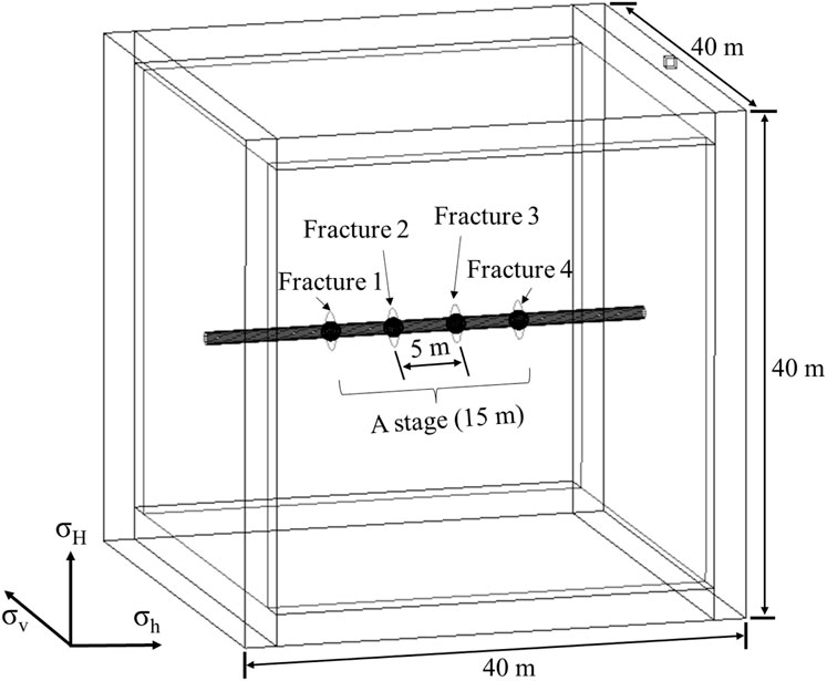
Figure 1. Numerical model of multi-cluster hydraulic fracture propagation.
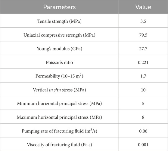
Table 1. Rock mechanical parameters and fracturing fluid pumping parameters used for the simulation study.
Differences in principal stress in the reservoir can significantly affect the complexity of the fracture formation during the fracturing. Stress anisotropy (SA) is usually used to characterize the horizontal principal stress difference. In order to investigate the influence of reservoir stress anisotropy on fracture extension, the maximum principal stress is kept constant at 8 MPa, and the minimum principal stress is set at levels of 7 MPa, 6 MPa, 5 MPa, 4 MPa, and 3 MPa. The injection rate is constant at 0.04 m3/s. Figure 2 reveals that the deflection degree of fracture extension is significantly higher in low-stress anisotropy cases compared to high-stress anisotropy cases. This result indicates that fracture propagation in a low-stress anisotropy field is susceptible to external stress field disturbance. In a high-stress anisotropy field, cracks are resistant to external stress fields and continue to propagate along their original direction.
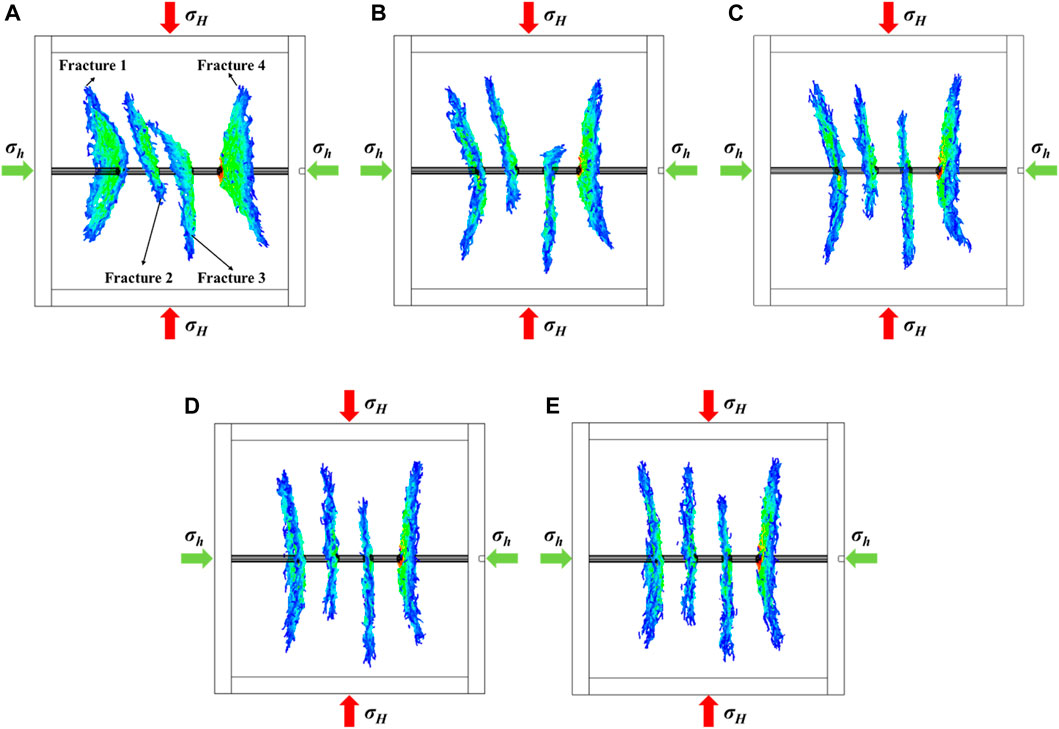
Figure 2. The propagation model of multi-fractures in the formation at varying levels of horizontal principal stress differences of 1 MPa (A), 2 MPa (B), 3 MPa (C), 4 MPa (D), and 5 MPa (E).
As shown in Figure 3A, the total stimulated area of the fracture increases with increasing stress anisotropy. Comparison of the stimulated area of the fracture at the same point in each case reveals that the stimulated area of each fracture consistently increases with increasing stress anisotropy. When there is a high level of stress anisotropy, the fracture is more likely to propagate along the direction of maximum principal stress. Additionally, a larger stimulated area allows the fracture to contact more reservoirs, thereby increasing the overall output. Figure 3B demonstrates that the fracture area expands rapidly with time, indicating that the fracture extension is greatly facilitated by the high-stress anisotropy of the fracture.
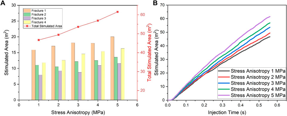
Figure 3. (A) The quantitative analysis of the multi-fracture area at varying horizontal principal stress differences. (B) The dynamic curve of the stimulated area during multi-cluster fracturing in the formation at varying horizontal stress anisotropy.
In most studies, the orientation of the horizontal wellbore is assumed to coincide with the minimum horizontal principal stress. However, horizontal wellbores are usually oriented at an angle to the minimum principal stress in actual oilfield operations. In this section, the effect of stress field direction on fracture extension is analyzed by changing the direction of the horizontal principal stress. Here, the principal stress orientation (PSO) is defined as the acute angle between the direction of the horizontal minimum principal stress and the direction of the wellbore. For example, when the PSO is 0°, the direction of the minimum principal stress is consistent with the direction of the wellbore, as shown in Figure 4A. Notably, when the PSO increases, the number of interconnected fractures increases accordingly. As a result, the overall length of the fracture extension is affected.
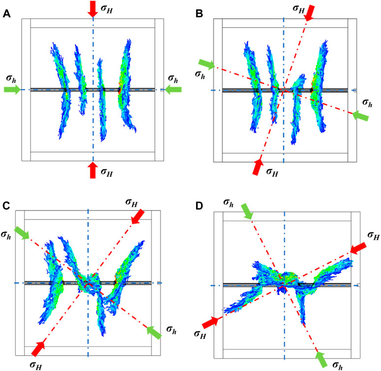
Figure 4. The propagation model of multi-fractures in the formation at different principal stress orientations of 0° (A), 20° (B), 40° (C), and 60° (D).
Figure 5A shows that the total stimulated area decreases with increasing stress direction, where the stimulated area of the cases with the PSO of 20° and 40° are numerical approximations. It can be seen from Figure 4B that when PSO is 20°, the fracture is minimally influenced by the orientation of the principal stress. Furthermore, its propagation direction remains perpendicular to the wellbore. Figure 4C shows that fractures 1 and 4 experience significant bending when the fracture PSO is 40°. This bending gradually occurs along the direction of the maximum principal stress because these fractures are influenced by the principal stress field. An intricate stress distribution consisting of a principal stress field and fracture stress shadow arises between fractures 2 and 3, resulting in the contact of these fractures throughout the extension stage. Hence, the primary difference between the two cases is that the middle two fractures span from being separate to interconnected. However, this alteration does not significantly affect the final area of fracture stimulation. Consequently, the fracture stimulation areas are similar in both cases. When the PSO is 60°, side fractures propagate parallel to the maximum principal stress, whereas the two middle fractures interconnect with fractures near the wellbore after reaching a certain length due to the stress shadow effect. Ultimately, the case of 60° PSO has the least stimulation area (Figure 4D). Figure 5B depicts the gradual increase in the stimulation area over time. In the initial fracture extension stage, the direction of the principal stress has a negligible effect on the fracture propagation. As a result, the stimulation area of the fracture remains closed. When the fracture extends beyond a certain distance, the stress shadows gradually increase, and the interference becomes more pronounced as the PSO increases.
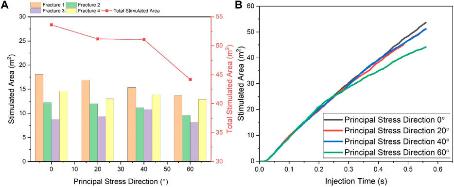
Figure 5. (A) The quantitative analysis of the multi-fractures area at different principal stress orientations. (B) The dynamic curve of the stimulation area during multi-cluster fracturing in the formation at different principal stress orientations.
The primary reason for employing fracturing treatments to stimulate unconventional reservoirs is their inherent brittleness, which significantly influences the propagation of hydraulic fractures and the fracture shape. The conventional methods for assessing shale brittleness rely on Young’s modulus and Poisson’s ratio. Thus, Young’s modulus is used as the variable to study the impact of Young’s modulus on fracture propagation in the reservoir. The study investigates the impact of reservoir brittleness on the propagation of multi-cluster fractures by changing the reservoir modulus. Figure 6 shows that the fracture length gradually increases with increasing Young’s modulus. In low Young’s modulus reservoirs, the limited fracture extension despite the same injection volume can be attributed to the increased brittleness of the reservoir caused by high Young’s modulus (Qiu et al., 2021). This brittleness leads to greater fracture extension. Additionally, the low Young’s modulus reservoirs exhibit larger fracture width but shorter fracture length.
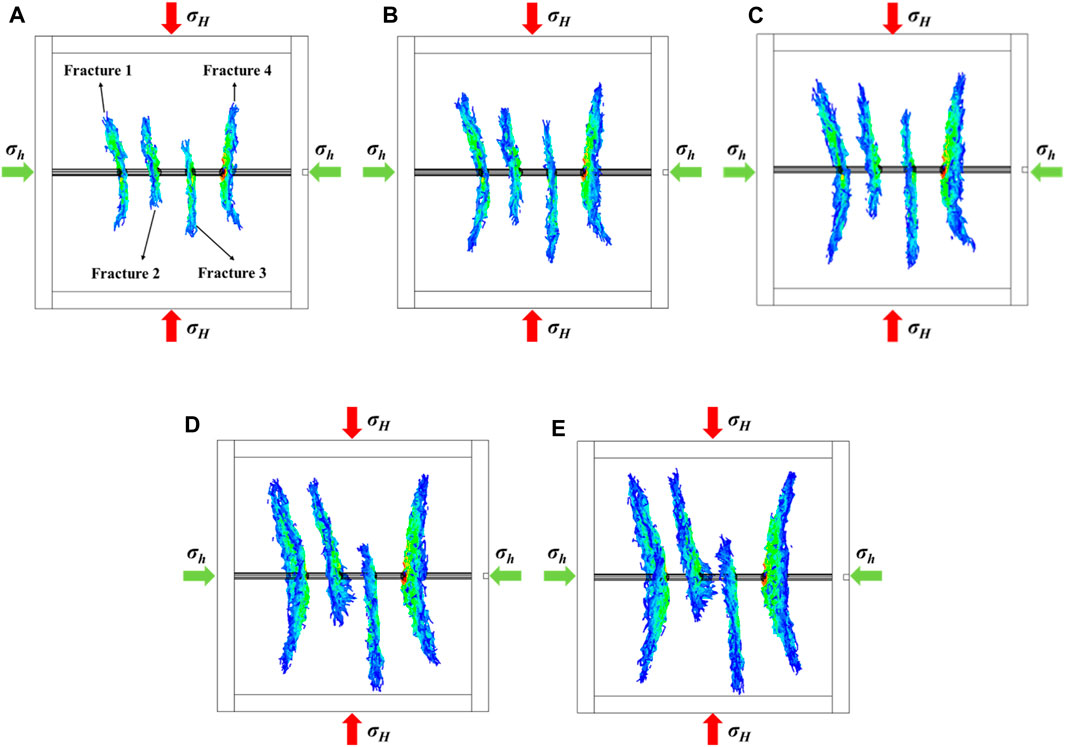
Figure 6. The propagation model of multi-fractures in the formation at Young’s moduli of 10 MPa (A), 20 MPa (B), 27.7 MPa (C), 40 MPa (D), and 50 MPa (E).
Figure 7A demonstrates that the total stimulation area significantly increases with increasing Young’s modulus. This phenomenon can be attributed to the impact of Young’s modulus on fracture generation. The low brittleness reservoir promotes the generation of fractures with shorter lengths but wider widths, whereas the high brittleness reservoir exhibits the opposite characteristics. Moreover, the comparison shows that the difference in fracture area is small at lower Young’s modulus and large at higher Young’s modulus. This difference can be attributed to differences in reservoir stress conductivity. Since the reservoirs with a high Young’s modulus facilitate the stress conduction, the stress shadow near the fracture has a significant impact on fracture extension. Figure 7B depicts the relationship between the total stimulated fracture area and the duration of fracture fluid injection in reservoirs with different Young’s modulus values throughout the fracturing process. It can be seen that the fracture propagation is facilitated by a high Young’s modulus.
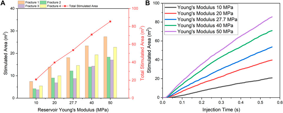
Figure 7. (A) The quantitative analysis of the multi-fractures area across different formations with varying Young’s moduli. (B) The dynamic curve of the stimulated area during multi-cluster fracturing in the formation at different reservoir Young’s moduli.
The number of fractures at each stage of the fracturing process is one of the most important factors affecting production. The number of fractures within a fixed distance affects the spacing between each fracture, resulting in stress shadows of different intensities. Cluster spacing for hydraulic fracturing in the Eagle Ford and Denver-Julesburg (DJ) basins is 5 m (Cheng, 2012; Lu, 2016; Somanchi et al., 2018). Thus, to analyze the impact of stress shadows and provide guidance for future fracturing treatments with relatively low cluster spacing, the propagation behaviors of fractures need to be examined. Four cases are illustrated in Figure 8, each with the same fluid injection volume. The number of fractures is set to 2, 3, 4, and 5, with corresponding fracture spacing of 15 m, 7.5 m, 5 m, and 3.75 m, respectively.
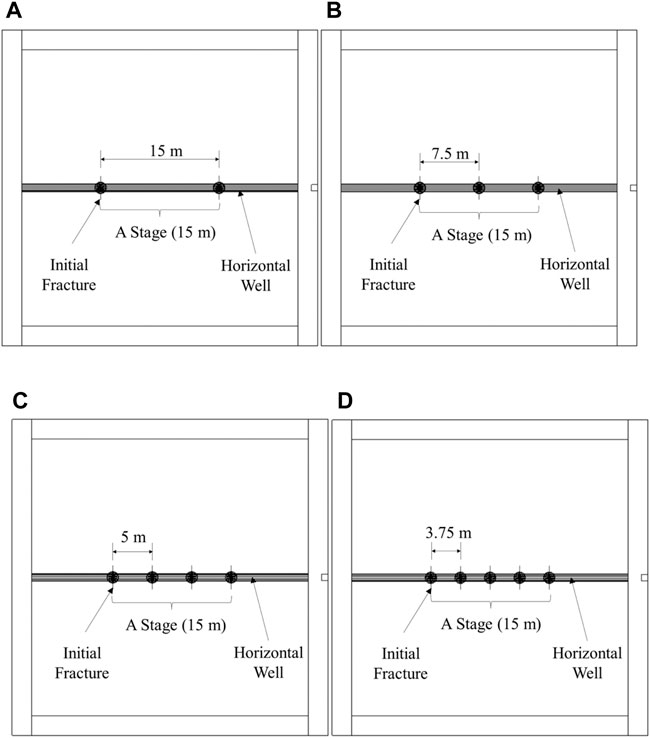
Figure 8. Multi-cluster hydraulic fracturing numerical models with different fracture numbers: (A) Case of two fractures. (B) Case of three fractures. (C) Case of four fractures. (D) Case of five fractures.
Figure 9 shows the width and geometry of the fractures after extension in each case. Different colors of the fracture surface correspond to distinct distributions of fracture widths. It can be seen that the fractures with a large fracture spacing are symmetrically distributed on both sides of the wellbore, and side fractures extend outwards due to the stress shadow. However, when the fracture spacing is limited, the fracture tends to extend unevenly. Figure 9C illustrates that fractures propagate on both sides of the wellbore, while the central section of the fractures can only extend along one side due to the constraint of stress shadow. Figure 9D shows that in the case of five fractures, each fracture has a distinct propagation pattern. Overall, as the number of fractures increases within a fixed length stage, the effects of fracture stress shadows become more serious. As a result, the distribution of fracture fluid along the wellbore becomes uneven, leading to varying patterns and morphologies of fracture propagation.
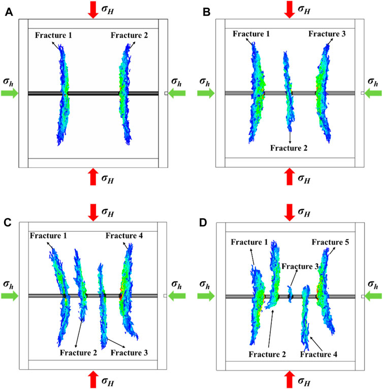
Figure 9. The propagation model of multi-fractures in the formation with different numbers of fractures: (A) Case of two fractures. (B) Case of three fractures. (C) Case of four fractures. (D) Case of five fractures.
The stimulated area of multi-stage hydraulic fracturing is shown in Figure 10. With the increase of fractures, the stimulated area of the fractures first increases and then decreases. When there are four fractures in a single stage (a fracture spacing of 5 m), the total stimulated area reaches its maximum. In the cases involving two fractures, the stimulated area of each fracture is nearly identical, suggesting a uniform dispersion of the fluid in both fractures. However, a greater number of fractures within a certain length results in more irregular dimensions of the fractures. As shown in Figure 9D, in the case of five fractures, the middle fracture (fracture 3) stops propagating under the influence of the strongest stress shadow, resulting in a stimulated area of zero. This result indicates that increasing the number of fractures in a single stage is not necessarily optimal when considering a certain stage length. Therefore, it is crucial to effectively exploit the stress shadow that exists between fractures.
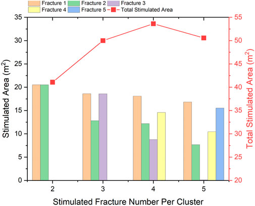
Figure 10. The quantitative analysis of the multi-fracture area with different numbers of fractures.
Figure 11 illustrates the temporal evolution of the cumulative total stimulated area for each fracturing case. It can be seen that the curves for the two fracturing cases are increasingly distant from the curves for other cases. It indicates that fewer fractures and longer fracture spacing cannot release the stimulation potential. However, as shown in the magnified image in the yellow section, factures grow slightly faster in the two-fracture case than in all other cases during the early extension stage. In the later stages of extension, the five-fracture case exhibits a greater fracture growth area than the other cases. This difference is because the wide fracture spacing produces less interference from fracture stress shadows in the early stage of fracture extension, enabling the fracture to grow rapidly. Moreover, in the late extension stage, the greater number of initiation fractures provides a larger stimulated area for the entire fracturing stage, even producing stronger stress shadow effects.

Figure 11. The dynamic curve of the stimulated area during multi-cluster fracturing in the formation with different numbers of fractures.
Fracturing fluid injection rate is a crucial factor affecting fracture morphology. In this part, the number of fractures in a single stage is set to 4 (fracture spacing is 5 m). Discussions of final fracturing patterns and production rates are only meaningful if the total fracturing fluid injection is the same. Therefore, to ensure the total injection volume is consistent, different injection times are set for each case.
Figure 12 shows the differences in fracture morphology for different injection rates. As the fracture injection rate increases, the fracture extends symmetrically to both sides of the wellbore with a more balanced distribution, especially for the middle two fractures in all cases. For side fractures, the deflection angle of the fractures transitions from nearly straight to a certain level of curvature with increasing fracture injection rate. The difference between intermediate and side fractures can be attributed to variations in the stress disturbance level. As shown in Figure 12A, all three fractures exhibit asymmetric extension at an injection rate of 0.02 m3/s, except for the fracture on the left side. However, when the injection rate increases to 0.1 m3/s, the fractures extend more evenly with a greater degree of deflection, as shown in Figure 12E. In conclusion, a high injection rate can benefit the generation of symmetrical fractures. The high injection rate facilitates rapid fracture formation during the fracture initiation stage, allowing the fracture to have enough energy to expand towards the pre-set direction and reducing the effect of stress shadows.
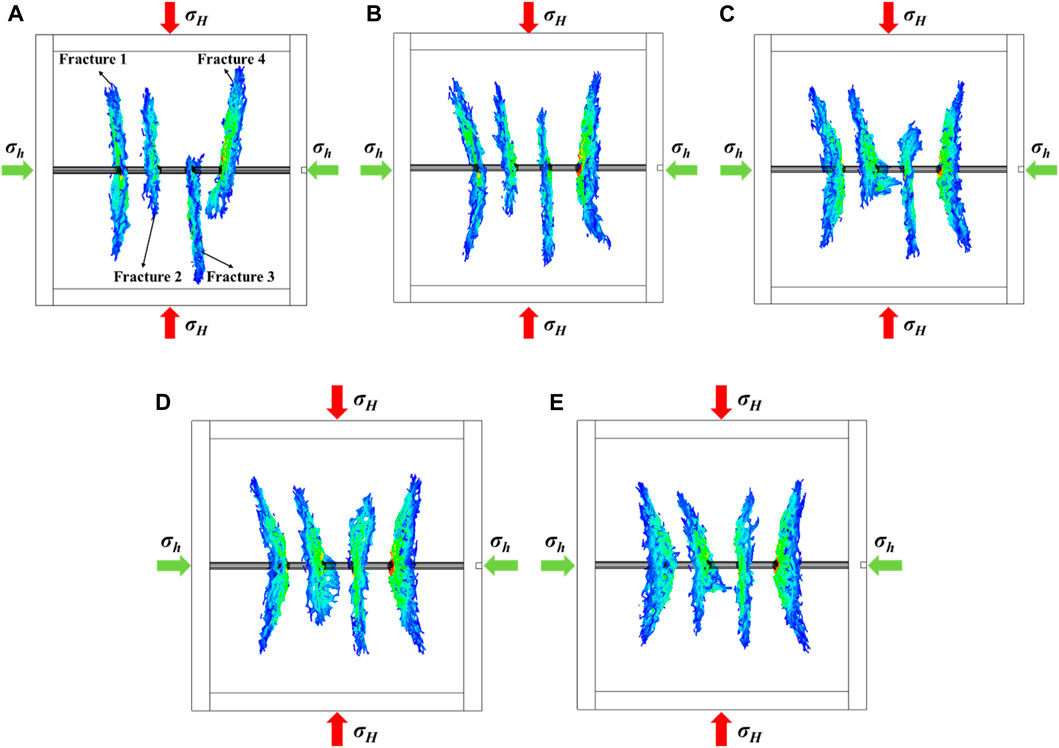
Figure 12. The propagation model of multi-fractures in the formation at different injection rates: (A) Injection rate of 0.02 m3/s. (B) Injection rate of 0.04 m3/s. (C) Injection rate of 0.06 m3/s. (D) Injection rate of 0.08 m3/s. (E) Injection rate of 0.1 m3/s.
Figure 13 illustrates the stimulated area for each fracture under the influence of different injection rates. Four fracture sizes are quantitatively analyzed for each case, and the effect of fracture injection rate on the stimulated area is compared. At low injection rates, the stimulated area of the side fracture is larger than that of the middle fractures. With the increase of injection rate, the stimulation area of side fractures decreases, and that of the middle fractures increases, resulting in a gradual approximation of the two fracture propagation modes. Therefore, a high injection rate is beneficial in promoting uniform distribution of multiple fracturing fluids. However, the uniform distribution of fluid also leads to increased stress interference between fractures, thereby reducing the total fracture stimulation area. Conversely, at a low injection rate case, although the fluid cannot be evenly distributed to each fracture, well-developed fractures can extend further due to reduced stress interference from other fractures, resulting in the largest total fracture area.
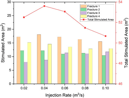
Figure 13. The quantitative analysis of the multi-fractures area at different injection rates.
Previous research has demonstrated that changing the injection rate of the fracturing fluid can effectively reduce the fracture initiation pressure and enhance the propagation capacity of hydraulic fractures (Patel et al., 2017; Ripudaman et al., 2018). Nevertheless, the suitability of a pumping mode with variable injection rates was barely investigated. Thus, this work analyzes the propagation behavior of multiple fractures under different pumping modes using a 3D lattice-based model. The fracturing fluid is pumped with four major models, as shown in Figure 14.
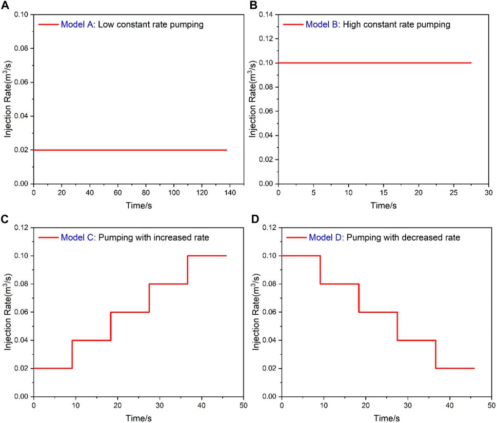
Figure 14. The four fracturing fluid pumping models: (A) Model A; (B) Model B; (C) Model C; (D) Model D.
Figure 15 shows that the propagation of multiple fractures with a short spacing distance is significantly affected by the pumping mode. A study of the dynamic fracture propagation process shows that relatively high constant rate pumping results in a uniform distribution of fluid across the four fractures compared to low-rate pumping. As a result, by continuously pumping a fluid with a high injection rate into the fracture, the fluid in the fracture can be ensured to retain sufficient energy to resist the formation stress exerted by the surrounding rock. As a result, uniform fracture evolution can be achieved even under the effect of fracture interference of multiple fractures. In model C, fractures 1 and 4 exhibit a consistent and steady extension, while fractures 2 and 3 present a distorted condition. Under model D, all fractures except for fracture 3 are symmetrically propagate along both sides of the wellbore. The wellbore is pressurized at a high injection rate, leading to high breakdown pressures during the fracture initiation. It creates a tensile fracture that can quickly penetrate the stress-shadowed area without being affected by stress shadows. Additionally, the high injection rate generates high fluid pressures within the fracture, which further helps to overcome the influence of stress shadows (Lecampion, 2012).
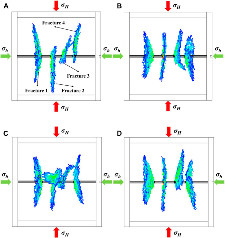
Figure 15. The propagation model of multi-fractures in the formation under different pumping modes: (A) Model A: low constant rate pumping of 0.02 m3/s; (B) Model B: high constant rate pumping of 0.1 m3/s; (C) Model C: increased pumping rate from 0.02 m3/s to 0.1 m3/s; (D) Model D: decreased pumping rate from 0.1 m3/s to 0.02 m3/s.
Figure 16 shows that the stimulation area of Model A is larger than that of Model B in the constant injection rate pumping mode. It indicates that a lower injection rate results in a larger fracture area, facilitating enhanced contact between the reservoir and wellbore. However, a low injection rate is not conducive to the uniform growth of adjacent fractures, which can also be proved by Figure 15. Under varying injection rates, the stimulation area of model D is larger compared to model C. Combined with Figures 15C, D, the pumping mode of model D facilitates the prompt evolution of fractures during the fracture initiation stage and mitigates the fracture interference. The above analysis demonstrates that the variable injection pumping mode with a decreasing injection rate of the fracturing fluid can achieve the optimal stimulation effect.
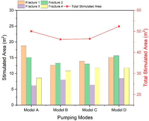
Figure 16. The quantitative analysis of the multi-fractures area at different injection rates.
The key factors determining fracture propagation in unconventional reservoirs can be briefly classified into geological and engineering factors. The engineering factors are associated with engineering strategies, and the geological factors refer to the geomechanical properties of reservoirs. Therefore, the identification of reservoirs with favorable geological and mechanical characteristics as the target layer, in conjunction with suitable fracturing treatment, can facilitate the evolution of hydraulic fractures to enhance hydrocarbon recovery.
A weighted study of the impact of geological features on fracture propagation is useful for optimizing the selection of target reservoirs. In order to evaluate the effects of the stress anisotropy, principal stress orientation, and Young’s modulus on the fracture geometry and production, the dimensionless stimulated area is defined as the ratio of the stimulated area of all cases to that in the baseline case. A value of 1 represents the fracture dimensionless stimulated area for the baseline case. Table 2 presents the range of geological uncertain parameters of this study. The horizontal coordinate in Figure 17 represents the dimensionless stimulated area, illustrating the effect of uncertainty parameters on the growth of the fracture stimulation area. The order of uncertainty parameters on the vertical coordinate is determined by the absolute difference between the maximum and minimum deviation of the normalized fracture stimulation area, indicating the effectiveness of the fracturing treatment. The orange bar indicates a positive effect, whereas the blue bar represents a negative effect. The black vertical line in the center represents the baseline in all cases. It can be seen from Figure 17 that Young’s modulus of the reservoir is the most important factor affecting fracture growth, followed by reservoir stress anisotropy and principal stress direction. Therefore, Young’s modulus of the reservoir will be the primary consideration when selecting the target reservoir.
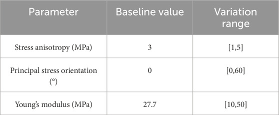
Table 2. The range of uncertain parameters on the fracture growth.
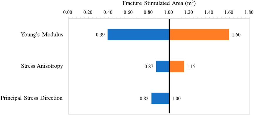
Figure 17. Tornado chart of the sensitivity studies based on the data of simulation cases.
Engineering parameters as operational controls provide the most effective means to optimize technology and enhance reservoir production. The perforation cluster spacing determines the fracture number at each stage. To increase the initial production rate of a single well, the spacing between perforation clusters is progressively reduced. However, the presence of stress shadows leads to uneven growth of multiple clusters in a single segment, which has been demonstrated in several studies (Miller et al., 2011; Bunger and Cardella, 2015). Generally, approximately 50% of the clusters are responsible for nearly 70% of the production. A similar phenomenon has been observed in this study (Figure 10).
In the early stage of hydraulic fracturing, a high fluid injection rate can help resist stress shadow around the wellbore. By gradually decreasing the fluid injection rate at the later stages, sufficient time can be reserved for further crack expansion. Furthermore, pumping modes with different injection rates can decrease the initiation pressure and facilitate the continuous propagation of fractures. The timing and magnitude of alterations in fluid injection rate must be carefully coordinated with the geological characteristics of the reservoir. Therefore, extensive experimental and theoretical investigations are needed to determine its optimal value to guide future studies.
In this paper, the lattice spring code XSite is used to study the influence of stress shadow between multiple hydraulic fractures during synchronous propagation. The simulation considers various factors, including stress anisotropy, principal stress orientation, reservoir Young’s modulus, fracture number, injection flow rate, and pumping mode. The conclusion of this study are as follows:
(1) The simultaneous propagation of several fractures results in stress shadow, which changes the local stress field and subsequently influences the direction of fracture propagation. Consequently, the fractures separate from each other and form complex non-planar shapes with branches in the cracks. The fractures are primarily perpendicular to the minimum principal stress, but side fractures are more noticeably deviated in the direction of the wellbore.
(2) Reservoir Young’s modulus has the greatest effect on fracture stimulation among all the factors that have been investigated. Enhancing Young’s modulus can enlarge the stimulated area for optimal production increase. Therefore, while selecting target reservoirs, fracturing reservoirs with a relatively high Young’s modulus can result in longer and larger stimulation fractures.
(3) The size of the fracture stimulation area initially increases and then decreases with increasing injection rate. At an injection rate of 0.04 m3/s, the maximum stimulation area is achieved. Additionally, higher injection rates facilitate uniform distribution of fluid volume within each fracture.
(4) The overall stimulated area of a single-stage fracture expands when a pumping pattern with decreasing injection rates is used for fracturing treatment. As a result, the extension capacity of hydraulic fracture is enhanced at higher and then lower injection rates.
This study focuses on the growth of multi-cluster fractures within a single stage. Subsequent research will be conducted on multi-stage hydraulic fracturing models for field scale.
The original contributions presented in the study are included in the article/Supplementary material, further inquiries can be directed to the corresponding author.
JW: Conceptualization, Writing–original draft. GP: Investigation, Writing–review and editing. LZ: Methodology, Writing–review and editing. ZC: Software, Writing–review and editing. BH: Formal Analysis, Writing–review and editing.
The author(s) declare that financial support was received for the research, authorship, and/or publication of this article. This work was financially supported by the National Natural Science Foundation of China (52174024) and The research was supported by the Shenyang Science and Technology Talent Project of China (No. RC230286).
Author LZ was employed by Luliang Oilfield Operation Area of Xinjiang Oilfield Branch Company, PetroChina.
The remaining authors declare that the research was conducted in the absence of any commercial or financial relationships that could be construed as a potential conflict of interest.
All claims expressed in this article are solely those of the authors and do not necessarily represent those of their affiliated organizations, or those of the publisher, the editors and the reviewers. Any product that may be evaluated in this article, or claim that may be made by its manufacturer, is not guaranteed or endorsed by the publisher.
Abass, H. H., Hedayati, S., and Meadows, D. L. (1996). Nonplanar fracture propagation from a horizontal wellbore: experimental study. SPE Prod. Facil. 11, 133–137. doi:10.2118/24823-pa
Bakhshi, E., Rasouli, V., Ghorbani, A., Fatehi Marji, M., Damjanac, B., and Wan, X. (2019). Lattice numerical simulations of lab-scale hydraulic fracture and natural interface interaction. Rock Mech. Rock Eng. 52, 1315–1337. doi:10.1007/s00603-018-1671-2
Bunger, A. P., and Cardella, D. J. (2015). Spatial distribution of production in a Marcellus Shale well: evidence for hydraulic fracture stress interaction. J. Pet. Sci. Eng. 133, 162–166. doi:10.1016/j.petrol.2015.05.021
Bunger, A. P., Jeffrey, R. G., Kear, J., Zhang, X., and Morgan, M. (2011). “Experimental investigation of the interaction among closely spaced hydraulic fractures,” in 45th US Rock Mechanics/ Geomechanics Symposium, San Francisco, California, USA, 26-29 June 2011.
Cheng, Y. (2012). Impacts of the number of perforation clusters and cluster spacing on production performance of horizontal shale-gas wells. SPE Reserv. Eval. Eng. 15, 31–40. doi:10.2118/138843-pa
Cong, Z., Li, Y., Pan, Y., Liu, B., Shi, Y., Wei, J., et al. (2022). Study on CO2 foam fracturing model and fracture propagation simulation. Energy 238, 121778. doi:10.1016/j.energy.2021.121778
Cong, Z., Li, Y., Liu, Y., and Xiao, Y. (2021). A new method for calculating the direction of fracture propagation by stress numerical search based on the displacement discontinuity method. Comput. Geotech. 140, 104482. doi:10.1016/j.compgeo.2021.104482
Damjanac, B., and Cundall, P. (2016). Application of distinct element methods to simulation of hydraulic fracturing in naturally fractured reservoirs. Comput. Geotechnics 71, 283–294. doi:10.1016/j.compgeo.2015.06.007
Dohmen, T., Zhang, J., and Blangy, J. P. (2014). “Measurement and analysis of 3D stress shadowing related to the spacing of hydraulic fracturing in unconventional reservoirs,” in SPE annual technical conference and exhibition (Malaysia: Society of Petroleum Engineers). doi:10.2118/170924-ms
Duan, K., Kwok, F., Zhang, Q., and Shang, J. (2020). On the initiation, propagation and reorientation of simultaneously-induced multiple hydraulic fractures. Comput. Geotechnics 117, 103226. doi:10.1016/j.compgeo.2019.103226
Fu, W., Savitski, A. A., Damjanac, B., and Bunger, A. P. (2019). Three-dimensional lattice simulation of hydraulic fracture interaction with natural fractures. Comput. Geotechnics 107, 214–234. doi:10.1016/j.compgeo.2018.11.023
Geyer, J. F., and Nemat-Nasser, S. (1982). Experimental investigation of thermally induced interacting cracks in brittle solids. Int. J. Solids Struct. 18, 349–356. doi:10.1016/0020-7683(82)90059-2
Han, W., Cui, Z., and Zhang, J. (2020). Fracture path interaction of two adjacent perforations subjected to different injection rate increments. Comput. Geotechnics 122, 103500. doi:10.1016/j.compgeo.2020.103500
Kumar, D., and Ghassemi, A. (2016). A three-dimensional analysis of simultaneous and sequential fracturing of horizontal wells. J. Petroleum Sci. Eng. 146, 1006–1025. doi:10.1016/j.petrol.2016.07.001
Lecampion, B. (2008). An extended finite element method for hydraulic fracture problems. Commun. Numer. Methods Eng. 25, 121–133. doi:10.1002/cnm.1111
Lecampion, B. (2012). Hydraulic fracture initiation from an open-hole: wellbore size, pressurization rate and fluid-solid coupling effects. Pap. Present. A. T. 46th U.S. Rock Mechanics/Geomechanics Symposium, Chic. Ill.
Li, Y., Peng, G., Tang, J., Zhang, J., Zhao, W., Liu, B., et al. (2023a). Thermo-hydro-mechanical coupling simulation for fracture propagation in CO2 fracturing based on phase-field model. Energy 284, 128629. doi:10.1016/j.energy.2023.128629
Li, Y., Wu, J., Zhang, J., Yang, H., Zeng, B., Xiao, Y., et al. (2023b). Optimization method of oriented perforation parameters improving uneven fractures initiation for horizontal well fracturing. Fuel 349, 128754. doi:10.1016/j.fuel.2023.128754
Liu, X., Rasouli, V., Guo, T., Qu, Z., Sun, Y., and Damjanac, B. (2020). Numerical simulation of stress shadow in multiple cluster hydraulic fracturing in horizontal wells based on lattice modelling. Eng. Fract. Mech. 238, 107278. doi:10.1016/j.engfracmech.2020.107278
Lu, Q. (2016). Unconventional reservoir perforating cluster spacing optimization method for staged-fracturing horizontal well. Malaysia: SPE Annu Tech. Conf. Exhib. doi:10.2118/184483-STUD023S099R025
Miller, C., Waters, G., and Rylander, E. (2011). “Evaluation of production log data from horizontal wells drilled in organic shales,” in North American Unconventional Gas Conference and Exhibition, The Woodlands, Texas, USA, 14–16 June 2011.
Olson, J. E., and Dahi-Taleghani, A. (2009). Modeling simultaneous growth of multiple hydraulic fractures and their interaction with natural fractures. SPE Hydraulic Fracturing Technology Conference.
Ooi, E. T., Song, C., Tin-Loi, F., and Yang, Z. (2012). Polygon scaled boundary finite elements for crack propagation modelling. Int. J. Numer. Methods Eng. 91 (3), 319–342. doi:10.1002/nme.4284
Patel, S. M., Sondergeld, C. H., and Rai, C. S. (2017). Laboratory studies of hydraulic fracturing by cyclic injection. Int. J. Rock Mech. Min. Sci. 95, 8–15. doi:10.1016/j.ijrmms.2017.03.008
Pollard, D. D., and Aydin, A. (1988). Progress in understanding jointing over the past century. Geol. Soc. Am. Bull. 100, 1181–1204. doi:10.1130/0016-7606(1988)100<1181:piujot>2.3.co;2
Qiu, D., Zhang, J., Lin, Y., Liu, J., Rabiei, M., Rasouli, V., et al. (2021). Lattice numerical simulations of hydraulic fracture propagation and their geometry evolution in transversely isotropic formations. Front. Earth Sci. 9, 787736. doi:10.3389/feart.2021.787736
Ripudaman, M., Eric, C., Prateek, B., Philip, C., and Mukul, M. (2018). Strategies for effective stimulation of multiple perforation clusters in horizontal wells. SPE Prod. Operations 33 (3), 539–556. doi:10.2118/179126-pa
Sani, A. M., Podhoretz, S. B., and Chambers, B. D. (2015). “The use of completion diagnostics in haynesville shale horizontal wells to monitor fracture propagation, well communication, and production impact,” in Proceedings of the SPE/CSUR Unconventional Resources Conference, Calgary, AB, Canada.
Sheng, M., Li, G., Sutula, D., Tian, S., and Bordas, S. P. (2018). XFEM modeling of multistage hydraulic fracturing in anisotropic shale formations. J. Petroleum Sci. Eng. 162, 801–812. doi:10.1016/j.petrol.2017.11.007
Sobhaniaragh, B., Mansur, W. J., and Peters, F. C. (2018). The role of stress interference in hydraulic fracturing of horizontal wells. Int. J. Rock Mech. Min. Sci. 106, 153–164. doi:10.1016/j.ijrmms.2018.04.024
Somanchi, K., Brewer, J., and Reynolds, A. (2018). Extreme limited-entry design improves distribution efficiency in plug-and-perforate completions: insights from FiberOptic diagnostics. SPE Drill. Complet 33, 298–306. doi:10.2118/184834-PA
Tian, F., Jin, Y., Jin, F., Ma, X., Shi, L., Zhang, J., et al. (2022). Multi-fracture synchronous propagation mechanism of multi-clustered fracturing in interlayered tight sandstone reservoir. Sustainability 14 (14), 8768. doi:10.3390/su14148768
Ugueto, C., Gustavo, A., Huckabee, P. T., Molenaar, M. M., Wyker, B., and Somanchi, K. (2016). “Perforation cluster efficiency of cemented plug and perf limited entry completions; Insights from fiber optics diagnostics,” in Proceedings of the SPE Hydraulic Fracturing Technology Conference, The Woodlands, TX, USA.
Wan, X., Rasouli, V., Damjanac, B., and Pu, H. (2020). Lattice simulation of hydraulic fracture containment in the North Perth Basin. J. Petroleum Sci. Eng. 188, 106904. doi:10.1016/j.petrol.2020.106904
Wang, B., Zhou, F., Zou, Y., Liang, T., Wang, D., Hu, J., et al. (2018). Effects of previously created fracture on the initiation and growth of subsequent fracture during TPMSF. Eng. Fract. Mech. 200, 312–326. doi:10.1016/j.engfracmech.2018.08.002
Wu, R., Kresse, O., Weng, X., Cohen, C. E., and Gu, H. (2012). “Modeling of interaction of hydraulic fractures in complex fracture networks,” in SPE Hydraulic Fracturing Technology Conference, The Woodlands, TX, USA.
Xiao, X., and Xiao, C. (2019). Analysis of initiation angle for fracture propagation considering stress interference. Energies 12 (10), 1841. doi:10.3390/en12101841
Xie, J., Huang, H., Sang, Y., Fan, Y., Chen, J., Wu, K., et al. (2019). Numerical study of simultaneous multiple fracture propagation in changning shale gas field. Energies 12 (7), 1335. doi:10.3390/en12071335
Xing, P., Yoshioka, K., Adachi, J., El-Fayoumi, A., Damjanac, B., and Bunger, A. P. (2018). Lattice simulation of laboratory hydraulic fracture containment in layered reservoirs. Comput. Geotechnics 100, 62–75. doi:10.1016/j.compgeo.2018.03.010
Yamamoto, K., Shimamoto, T., and Sukemura, S. (2004). Multiple fracture propagation model for a three-dimensional hydraulic fracturing simulator. Int. J. Geomechanics 4 (1), 46–57. doi:10.1061/(asce)1532-3641(2004)4:1(46)
Zhang, H., Chen, J., Li, Z., Hu, H., and Mei, Y. (2024). Numerical simulation of multi-cluster fracturing using the triaxiality dependent cohesive zone model in a shale reservoir with mineral heterogeneity. Rock Mech. Rock Eng. 57, 325–349. doi:10.1007/s00603-023-03527-5
Zhang, J., Li, Y., Pan, Y., Wang, X., Yan, M., and Shi, X. (2021). Experiments and analysis on the influence of multiple closed cemented natural fractures on hydraulic fracture propagation in a tight sandstone reservoir. Eng. Geol. 281, 105981. doi:10.1016/j.enggeo.2020.105981
Zheng, H., Pu, C., Wang, Y., and Sun, C. (2020). Experimental and numerical investigation on influence of pore pressure distribution on multi-fractures propagation in tight sandstone. Eng. Fract. Mech. 230, 106993. doi:10.1016/j.engfracmech.2020.106993
Keywords: lattice-based method, stress shadow, multi-cluster fractures, stimulated area, pumping mode
Citation: Wang J, Peng G, Zhang L, Cong Z and Hu B (2024) Simulation and optimization of unstable dynamic propagation of multiple fractures in the shale formation. Front. Earth Sci. 12:1394491. doi: 10.3389/feart.2024.1394491
Received: 01 March 2024; Accepted: 18 March 2024;
Published: 10 April 2024.
Edited by:
Xixin Wang, Yangtze University, ChinaReviewed by:
Xiaoran Wang, China University of Mining and Technology, ChinaCopyright © 2024 Wang, Peng, Zhang, Cong and Hu. This is an open-access article distributed under the terms of the Creative Commons Attribution License (CC BY). The use, distribution or reproduction in other forums is permitted, provided the original author(s) and the copyright owner(s) are credited and that the original publication in this journal is cited, in accordance with accepted academic practice. No use, distribution or reproduction is permitted which does not comply with these terms.
*Correspondence: Jue Wang, d2FuZ2p1ZUBuZXB1LmVkdS5jbg==
Disclaimer: All claims expressed in this article are solely those of the authors and do not necessarily represent those of their affiliated organizations, or those of the publisher, the editors and the reviewers. Any product that may be evaluated in this article or claim that may be made by its manufacturer is not guaranteed or endorsed by the publisher.
Research integrity at Frontiers
Learn more about the work of our research integrity team to safeguard the quality of each article we publish.