 Mengchao Xu
 Xiaoshuang Li
 Jiawen Wang3*
- 1School of Civil Engineering, Shaoxing University, Shaoxing, China
- 2College of Civil Engineering, Qilu Institute of Technology, Jinan, Shandong, China
- 3School of Resources and Environmental Engineering, Jiangxi University of Science and Technology, Ganzhou, China
- 4Ynnan Phosphate Chemical Group Co., Ltd., Kunming, China
Introduction: Taking a phosphate mine in Yunnan as the engineering research background, the fractured rock mass of the No. 1 belt roadway is selected as the research object.
Methods: To reduce the cost of tunnel surrounding rock support and optimize construction technology, a combination of numerical simulation software Midas and on-site experiments was used to compare and analyze the distribution characteristics of the plastic zone of tunnel surrounding rock, deformation characteristics of tunnel surrounding rock, and stress characteristics of tunnel support anchor bolts under two support methods: double-layer spray anchor mesh and single-layer spray anchor mesh with steel bar.
Results: Research findings indicate that adopting the single-layer spray anchor mesh with steel bar support method results in a more uniform distribution of the plastic zone at the top of the tunnel surrounding rock, with a smaller range. The settlement of the roof and bulging of the bottom plate in the roadway’s surrounding rock, supported by a single-layer spray anchor mesh and steel bars, measure at 75.033 mm and 82.165 mm, respectively. Additionally, the internal bulging on both sides of the roadway’s surrounding rock is recorded as 37.835 mm and 37.470 mm, respectively. On the other hand, when utilizing a double-layer spray anchor mesh for support, the settlement of the roof and bulging of the bottom plate in the roadway’s surrounding rock are measured at 84.199 mm and 85.255 mm, respectively. Correspondingly, the internal bulging on both sides of the roadway’s surrounding rock records measurements of 41.670 mm and 41.756 mm, respectively. Furthermore, adopting the single-layer spray anchor mesh with steel bar support method ensures a more even transfer of axial forces to the steel bars, thereby increasing the overall load-bearing capacity. In contrast, the anchor bolts in the double-layer spray anchor mesh support method experience higher axial forces, leading to more pronounced stress concentration.
Discussion: By comparing the field monitoring data, it is evident that the single-layer spray anchor mesh with steel bar support method exhibits significantly better control over the tunnel surrounding rock than the double-layer spray anchor mesh support method. Therefore, replacing the double-layer spray anchor net support with a single-layer spray anchor net with steel bar support method is entirely feasible and can meet on-site practical production requirements. The research results hold significant value in providing guidance and reference for selecting cost-effective support schemes for tunnel surrounding rock.
1 Introduction
The southwestern region of China boasts abundant phosphorus resources, particularly in the Yunnan region, which accounts for 23.59% of the country’s total phosphorus reserves. Additionally, this region’s annual production of phosphorus mines represents approximately 30% of the national output. Yunnan phosphate ore has a state of “gentle inclination, medium thickness layer, and multiple interlayers,” with an average inclination angle of 15°. During underground mining operations, tunnel excavation disrupts the original equilibrium state of the adjacent surrounding rocks, leading to disturbances. As a result, the unloading process is interrupted. The excavation process causes the redistribution and adjustment of the surrounding rock, eventually reaching a new equilibrium state. The initial complex compressive state within the surrounding rock transforms into a tensile and shear state. To address the stress redistribution phenomenon in the roadway’s surrounding rock, it becomes necessary to support the roadway and mitigate the arch displacement and subsidence caused by stress changes in the surrounding rock.
Numerous scholars have conducted extensive research on the stability and support methods of surrounding rock tunnels, yielding significant findings. (Yang and Zhao, 2023) analyzed the stress distribution characteristics and tunnel stability of surrounding rock under varying burial depths, width-to-height ratios, and mechanical parameters of the surrounding rock. As a result, an optimization plan was proposed, which involves strengthening the roof with anchor rods and grouting on both sides of the tunnel. In another study, (Qin et al., 2023) summarized and analyzed the deformation characteristics of the surrounding rock in deep hard rock tunnels, considering complex geological conditions. Based on the rock conditions and deformation laws of the surrounding area, a support method combining “resin anchor rods, metal mesh, and shotcrete” was proposed. This approach has proven effective in reducing the deformation of the surrounding rock. These research contributions have significantly advanced our understanding of tunnel stability and support methods for surrounding rock, providing valuable insights for designing and implementing effective support systems in similar geological contexts. (Yang and Chen, 2023) have proposed a multi-gradient support technology that involves a staged approach to supporting the roof, upper and lower walls, and subsequent reinforcement. The feasibility of this technology was analyzed using Flac3D numerical simulation software. In a separate study, (Ma et al., 2023) utilized the Kastner formula and Flac3D numerical simulation software to investigate the relationship between support resistance and plastic zone failure in the surrounding rock. Their research aimed to understand the factors influencing support resistance. (Tang et al., 2023) analyzed the formation process of the Przewalski arch in the tunnel’s surrounding rock based on geological and mechanical test results. By establishing the curve equation of the Przewalski arch, they studied the stress state of the top and sides of the development tunnel and calculated the relevant support parameters. (Han, 2023) employed Flac3D software to construct a numerical simulation model. Their study focused on the impact of anchor parameters such as length, prestress, and spacing on the additional stress of the tunnel’s surrounding rock. Ultimately, they obtained optimal anchor support parameters through their research. These studies have contributed to advancing knowledge in tunnel support technologies, providing valuable insights into the design and implementation of effective support systems for the surrounding rock in tunnel construction. (Ren, 2023) conducted numerical simulations and on-site testing to analyze the deformation characteristics of the surrounding rock in a test tunnel under different working conditions. They proposed a zoning anchor injection spray joint control technology. In a separate study, (Han et al., 2023) examined the impact of tunnel burial depth and surrounding rock strength on the shape and extent of the plastic zone. They also investigated how different tunnel support methods and actual support measures affect the butterfly-shaped plastic zone in the surrounding rock. (Kang et al., 2023) focused on determining the optimal timing for implementing various measures, such as pre-stressed anchor rods, brackets, shotcrete, pre-stressed anchor cables, and deep hole grouting, based on different levels of surrounding rock. They introduced a precise distribution joint support technology for deep rock tunnels to intervene in the surrounding rock structure. (Chen, 2023) simulated anchor mesh support structures using on-site construction methods. They quantified the safety of these structures and established empirical formulas to evaluate their effectiveness. Their research provided quantitative indicators for assessing the safety of tunnel support. These studies have contributed valuable insights into the behavior of surrounding rock in tunnel construction. The proposed technologies and analysis methods enhance our understanding of tunnel support systems and aid in the development of more effective and reliable approaches.
Chinese researchers have accumulated a wealth of experience in the field of tunnel surrounding rock support technology. Currently, the main support methods include pre-stressed anchor rod support, steel mesh support, spray anchor support, cast-in-place concrete support, steel support, rock anchor support, and others (Yang et al., 2018; Ren et al., 2023a; Ren et al., 2023b). These methods can increase the stability of the surrounding rock, reduce deformation and cracking, disperse ground stress, and prevent water infiltration and other underground media. The research methods for surrounding rock support methods, both domestically and abroad, primarily use a combination of numerical simulation software and engineering experiments. Research focuses on studying the influence of different support methods on the stability of surrounding rock, the design and optimization of support structures, the development of different support materials and technologies, and the interaction law between surrounding rock and support structures. These studies have greatly advanced our understanding of tunnel support systems and led to the development of more effective and reliable approaches.
This study focuses on this specific research objective to reduce the support cost of the fractured roadway in an underground phosphate mine located in Yunnan and streamline the construction process. The research systematically investigated the impact of two support methods, double-layer spray anchor mesh and single-layer spray anchor meshwith steel bars, on the surrounding rock of the No. 1 belt roadway in the fractured rock section of Yunnan Phosphate Mine. The relevant research results hold great significance in offering insights and reference points for developing cost-effective support schemes for tunnel surrounding rock, both domestically and internationally. The technical findings from the research are not confined to phosphorus mines but are broadly applicable to various types of support scenarios.
2 Project overview
2.1 Geological conditions around the mining area
The study section of Yunnan Phosphate Mine Ridge extends in a long serpentine shape from the southwest to the northeast, with a terrain that is higher in the north and lower in the south. The highest elevation, reaching 2335 m, is observed at the edge of the mining boundary in the northern part of the mining area. On the other hand, the lowest elevation, measuring 1838.7 m, is found near the mining boundary in the southwestern part of the area, which serves as the lowest erosion benchmark within the mining area. Consequently, a relative height difference of 496.3 m exists. The mining area is situated in a zone characterized by a gentle slope and deep groundwater burial, with no significant surface water bodies present within or near the mining vicinity. The terrain slope in the mining area is relatively mild, and there are no residential villages located within it (Huang et al., 2022; Liu, 2022).
The geological structure of the research section is relatively simple, with strong weathering strata present in the shallow part of the mining area. The rock layers in the mining area have a gentle dip angle, and the rock mass is locally fractured, which may affect its stability. Fortunately, the slope of the mining pit is relatively stable. However, due to the presence of soluble rock and clastic rock, different support schemes will need to be adopted for the surrounding rock of this type of roadway.
2.2 Specific situation of 1 # belt roadway
The fracture structure of the rock mass near the 1# belt roadway is not extensively developed, exhibiting a dip angle of approximately 150° and a dip angle range of 10°–30°. In general, it displays a monoclinic structure that gently slopes towards the southeast. The mining area is situated close to the ore storage yard on the northern side of the 450 beneficiation plant, at an elevation of 1890 m. The planned length for the inclined section of the middle transportation belt roadway is 786.8 m, designed as a three-core arch section for the belt inclined shaft. The excavation width of the roadway measures 4.8 m, with an excavation height of 3.65 m and a wall height of 2.0 m. The total excavation section amounts to 16.56 m2, and the support method employed involves spray anchor mesh support.
3 Stress analysis of tunnel surrounding rock
Taking the 1# three-core arch roadway located at a depth of 1890 m in a phosphate mine in Yunnan as the subject of analysis, this study aims to analyze the stress distribution of the surrounding rock during excavation. The three-core arch roadway can be regarded as equivalent to a circular roadway for stress analysis purposes. Excavation activities inevitably disrupt the original stress state of the surrounding rock. Therefore, understanding the stress distribution of the surrounding rock plays a vital role in guiding support design (Hou et al., 2023a; Hou et al., 2023b). By applying principles from elastic-plastic mechanics and material mechanics, the tunnel, with its certain thickness, can be simplified as an elastic, thin-walled cylindrical mechanical model subjected to uniformly distributed external pressure for calculation purposes. Refer to Figure 1 for a visual representation of the specific model.
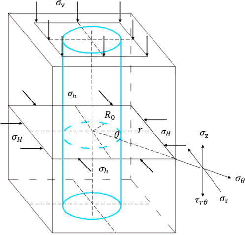
FIGURE 1. Mechanical model of thin-walled cylindrical shafts and tunnels.
During the actual construction process, significant stress changes can result in instability of the wellbore. Therefore, when deriving the stress on the surrounding rock of the wellbore, it is necessary to meet the following three conditions: (1) the formation is a transversely isotropic and linear elastic medium; (2) the plane strain condition is met to calculate the stress distribution around the wellbore; (3) the medium is uniformly continuous.
1. Due to stress
2. Due to stress
In the formula:
By analyzing formulas 1−9, we can conclude that
As it penetrates deeper into the surrounding rock,
Thus, as
4 Indoor rock mechanics tests
4.1 Rock mass quality classification
The Geological Strength Index (GSI), developed by Hoek, Kaiser, and Brown in 1995, serves as a measure to assess the strength of rock masses under varying geological conditions. GSI takes into account factors such as the geological environment, structural characteristics, and surface properties of the rock mass. In the past, however, there was a deficiency in quantifying the description of rock mass structure or morphology, which posed challenges in accurately determining the GSI value of the rock mass (Yin et al., 2023). To address this issue, the rock mass quality grade is quantified by incorporating the rock mass rating (RMR) classification method. According to Z.T. Bieniawski’s research, the revised RMR index value holds an equivalent relationship with the GSI value, allowing for the estimation of the GSI value by determining the revised RMR index value (Cai et al., 2001). The South African Council for Science and Research (CSIR)’s Z.J. proposed RMR classification method, presented in Table 1, is utilized to classify the ore rock stability in the study area, based on the investigation results of the rock mass organization and supplemented by the findings of rock mechanics experiments. Its mathematical expression is as follows:
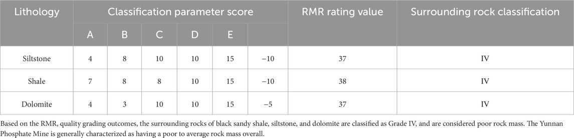
TABLE 1. RMR quality classification.
In the formula,
By employing a scoring method to assess the quality of the rock mass, it is possible to classify the rock mass into five categories based on the sum of the obtained scoring values. A rock mass scoring below 20 is categorized as very poor (Grade V). A score ranging from 21 to 40 indicates a poor rock mass (Grade IV). A rock mass rating between 41 and 60 signifies a generally acceptable rock mass (Grade III). A score ranging from 61 to 80 represents a good rock mass (Grade II). Finally, a score between 81 and 100 denotes a highly desirable rock mass (Grade I). Through a thorough examination of investigation results, relevant experiments, and calculations, and taking into account the lithology similarities, the RMR values and their corresponding evaluation levels can be derived for each lithology. These values are presented in Table 1.
4.2 Hoek-Brown criterion
Obtain rock samples surrounding the tunnel from the on-site research section and process them into standard samples with a height of 100 mm and a radius of 50 mm. The samples obtained from the research are depicted in Figures 2, 3. Indoor triaxial compression tests were conducted to obtain experimental data for rock mechanics tests, which were then reduced based on the Hoek-Brown criterion for rock mechanics parameters (Gao et al., 2023). In 2002, E. Hoek revised the previous Hoek Brown criteria and made improvements to
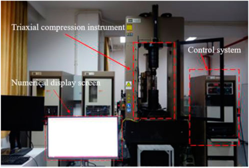
FIGURE 2. MTS815.04 high rigidity rock mechanics test system.
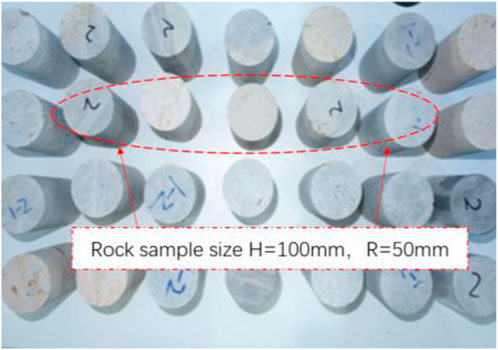
FIGURE 3. Processed rock sample.
Among them,
In formulas 10−15,
Utilizing the aforementioned Hoek Brown empirical formula, a series of indoor rock mechanics tests were carried out to ascertain the parameters of shale, siltstone, and dolomite rock formations. The refined rock mechanics parameters have been presented in Table 2.
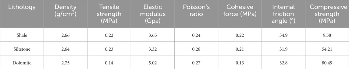
TABLE 2. Summary of selected rock mechanics parameters.
5 Introduction to support scheme for broken surrounding rock
5.1 Introduction to different support plans
5.1.1 Double-layer spray anchor mesh support
The geological conditions in the Yunnan Phosphate Mine are relatively complex, with incomplete development of the selected structural planes. The overall strength of the rock mass is low, and the inclination angle of the geological layer in the excavation section is 14.5°. During the long-term tunnel excavation process, the tunnel is primarily supported by a double-layer spray anchor mesh system, while the excavation section features a three-core arch design. The excavation section is 16.56 square meters, with a width of 5.2 m, a height of 3.90 m, and a wall height of 2.0 m. The design of the tunnel section is shown in Figure 4. The anchor rods utilized in this scenario are made of HRB400 grade threaded steel bar. They measure 2000 mm in length, with a drilling hole diameter of 28 mm. These anchor rods are spaced at intervals of 1000 mm × 2000 mm. Additionally, they boast a pull-out resistance exceeding 50 kN. The anchor rod trays are made of Q215 steel plate, with a thickness of 10 mm and a size of 200 mm × 200 mm. The thickness of the sprayed concrete is 100 mm.

FIGURE 4. Double-layer spray anchor mesh support.
In the early stage of rich ore mining, the grade of phosphate ore is high, and the rock mass is severely fractured. The use of double-layer spray anchor mesh support can effectively reduce the displacement and subsidence of the surrounding rock of the roadway. However, when the excavation reached 1890 m, the grade of the phosphate ore decreased significantly, the yield was lower, the rock fractures developed well, there were fewer fractured sections, and the overall strength of the rock mass was higher. The cost of using double-layer spray anchor mesh support is relatively high, and the construction process of using double-layer spray anchor mesh support is complex, and the work intensity of on-site workers is high. Therefore, it is urgent to choose new support technology, simplify the construction process, reduce support costs, and improve economic benefits while meeting the safety requirements of support.
5.1.2 Single layer spray anchor net with steel bar support
The tunnel section with unstable surrounding rock is susceptible to fragmentation, and the effectiveness of anchor rod support is relatively moderate. In the deeper parts of the tunnel, the fractured rock is unable to effectively convert the tension of the anchor rod into consolidation force, resulting in a reduced constraint range of the anchor rod on the internal rock mass of the surrounding rock. This poor interaction between the anchor rod and the surrounding rock hinders effective control over the movement of the rock mass (Wang et al., 2016; Li et al., 2023). The combination of reinforcement bars with anchor rods, known as the reinforcement spray anchor net support with reinforcement bar support method, is a reinforcement technique. The arrangement of the reinforcement bars is depicted in Figure 5. During the installation of the anchor rods, a pre-tensioning force is applied to the tail of the anchor rod via a cushion plate, and the steel bars are securely fixed on the surface of the surrounding rock. This results in an integrated structure on the support surface, with the cushion plate and steel bars working together. The settlement of the surrounding rock is absorbed by the steel bars, and the tension is transmitted to the anchor rod through the cushion plate. The anchor rod then transmits this tension to the deep surrounding rock, thus fully utilizing the strength of the deep surrounding rock to maximize interaction force between the same layer of surrounding rock. Simultaneously, implementing a single-layer spray anchor mesh with steel bar support can enhance the interaction force between the anchor rod, steel bar, and spray layer. This improves the overall integrity and tensile strength of the spray layer. Following deformation, the surrounding rock comes into contact with the strengthened shotcrete layer and reacts with it, providing excellent support for the surrounding rock.
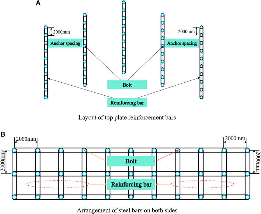
FIGURE 5. Layout of single-layer spray anchor mesh reinforcement bars.
5.2 Numerical model establishment
5.2.1 Tunnel surrounding rock support model
Taking the example of the 1# belt main roadway in Yunnan Phosphate Mine, the calculation involves the analysis of the surrounding rock conditions. The roadway primarily traverses through a sandstone layer, with shale as the upper layer and dolomite as the lower layer. The roadway is predominantly horizontal, featuring a three-core arch cross-section. A tunnel model is created to simulate the actual engineering geological conditions. The top shale layer has a height of 15 m, followed by a middle sandstone layer with a height of 20 m, and finally, a bottom dolomite layer with a height of 20 m. The model has a width of 50 m, and the depth along the direction of the surrounding rock tunnel mining is 20 m. A construction support section is arranged every 2 m, resulting in a total of 10 surrounding rock support sections.
Utilizing the Midas finite element software, a tunnel excavation model was constructed based on the actual geological properties of the ore. The complete model consists of 120 geometric quantities, 113374 node quantities, and 140075 unit quantities. We performed rigorous accuracy testing on the generated tunnel support grid to ensure the coupling of the grid nodes. Midas comes with an in-built grid quality inspection tool that enables checking for the quality and features of the generated grid. As depicted in Figure 6, the entire model exhibits a “hollow cage” appearance, signifying that the generated grid nodes are well-coupled and display excellent convergence.
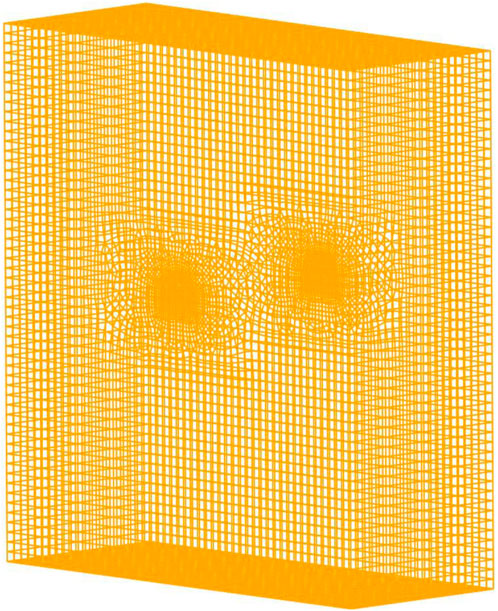
FIGURE 6. Grid quality inspection model.
The material properties of the rock mass are determined using the modified Hoek Brown criterion. Anchor rods, shotcrete, and steel bars all adhere to isotropic elastic criteria. Shale, siltstone, and dolomite are represented as 3D solid units, anchor rods as 1D embedded truss structures, shotcrete as 2D slab unit structures, and steel bars as 1D embedded beam unit structures. In the numerical simulation process, the steel bars and the anchor rod tail tray are fully connected and fixed. Figure 7 illustrates the established numerical simulation calculation model of the tunnel support structure.
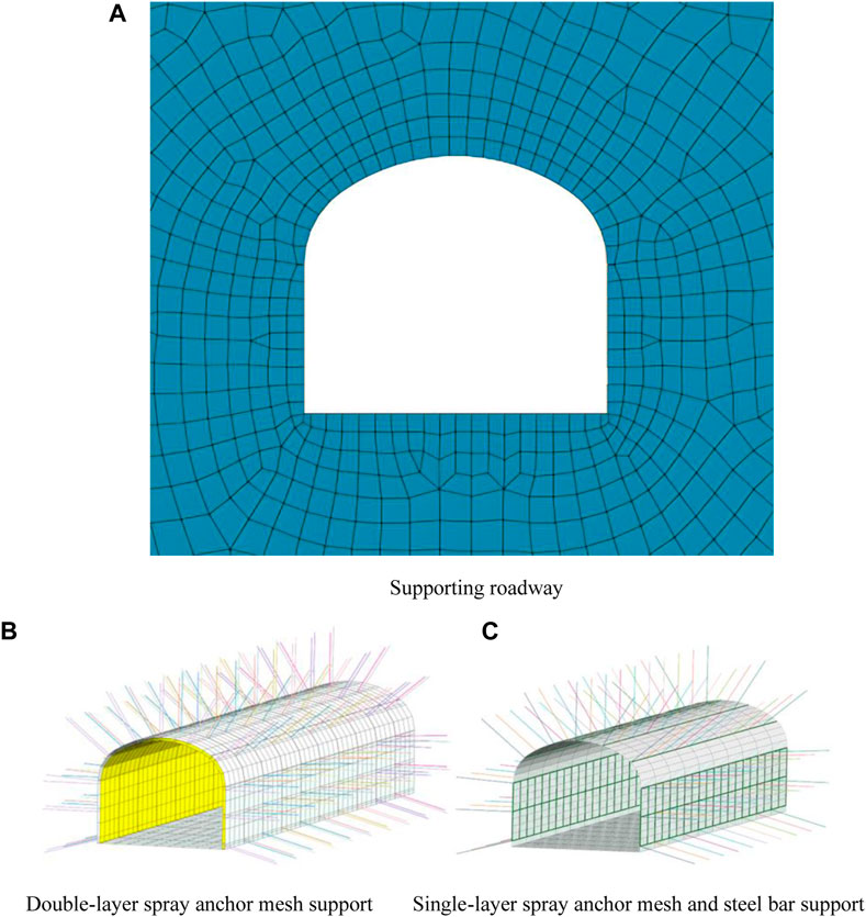
FIGURE 7. Numerical simulation of roadway and support structure.
5.2.2 Initial conditions and material parameters
To ensure the accuracy and reasonableness of the model calculations, boundary and gravity constraints are implemented on the numerical model to prevent axial displacement during analysis. Additionally, during the construction phase setup, an initial displacement zeroing is applied to the model to avoid any impact on the final calculation results. In reference to previous research reports on Yunnan Phosphate Mine, the material properties for roadway support in this area are presented in the table below. The material parameters for anchor rods and sprayed concrete layers containing metal mesh can be found in Tables 3, 4, respectively, while Table 5 provides the material properties of steel bars.
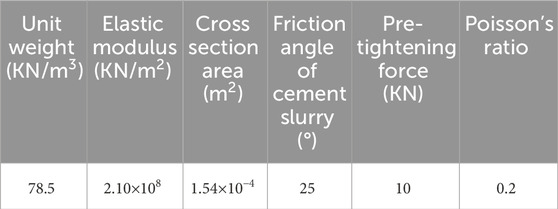
TABLE 3. Parameters of threaded steel anchor rods.
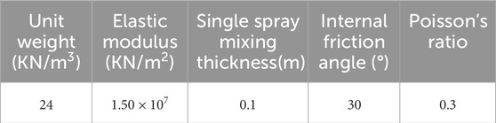
TABLE 4. Spray layer parameters containing the metal mesh.
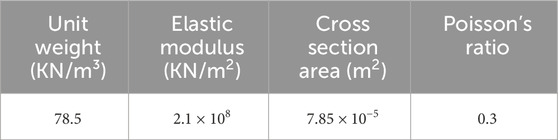
TABLE 5. Material property parameters of reinforcement bars.
5.2.3 Numeric calculation scheme
After establishing the model and achieving initial displacement balance, two methods of roadway support are implemented: double-layer spray anchor mesh, and single-layer spray anchor mesh with steel bars. The distribution characteristics of the plastic zone in the surrounding rock of the roadway, the deformation characteristics of the surrounding rock, and the stress characteristics of the roadway support anchor bolts are compared and analyzed under these two support methods. These three indicators serve to evaluate the effectiveness of the support. By analyzing the results of the numerical simulation, the feasibility of utilizing the single-layer spray anchor mesh with steel bar support technology is determined.
6 Analysis of numerical simulation calculation results
6.1 Distribution characteristics of plastic zone in tunnel surrounding rock
Figure 8 shows the distribution characteristics of the plastic zone in the surrounding rock of the tunnel under different support methods after excavation. Figures 8A, B are compared, revealing a large plastic zone around the roadway supported by double-layer spray anchor mesh. The plastic zone in some areas of the top plate is relatively small, gradually spreading to the surrounding areas, and the plastic zone in the bottom plate is the smallest. When using single-layer spray anchor mesh with steel bar support, the plastic zone of the tunnel is still mainly a shear failure, indicating that the failure mode of the tunnel surrounding rock is not greatly affected by the support method. Instead, it mainly depends on the rock mass properties and the distribution of stress. Although the range of plastic zones on the roof has increased after using single-layer spray anchor mesh and steel reinforcement support technology, the extension area of plastic zones on both sides of the roadway is significantly smaller than when using double-layer spray anchor mesh. By observing the distribution of plastic zones under the two types of support in Figure 8, it can be seen that the use of single-layer spray anchor mesh with steel bar support effectively reduces the distribution range of plastic zones in the surrounding rock of the roof and the distribution range is more uniform. This indicates that the use of steel bar support can strengthen the connection between the surrounding rock and the support structure and, by relying on its own mechanical properties, effectively improve the distribution pattern of the plastic zone in the surrounding rock.
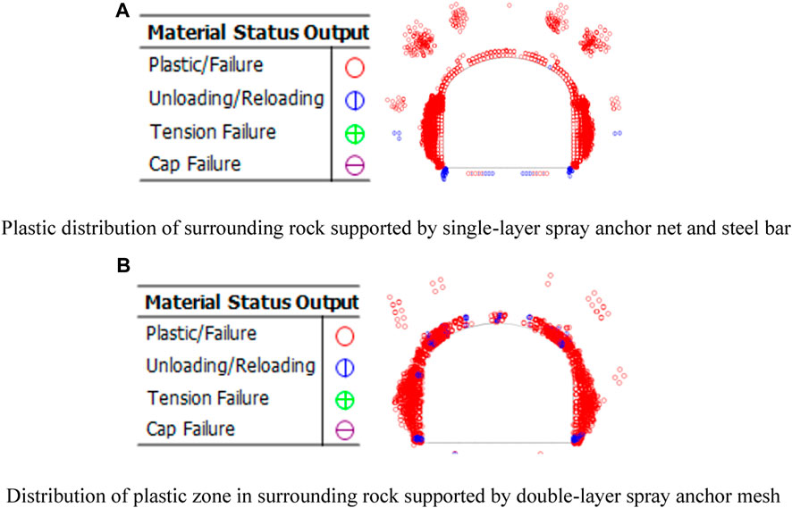
FIGURE 8. Distribution characteristics of the plastic zone in surrounding rock under different support methods.
6.2 Deformation characteristics of surrounding rock in tunnels
Figures 9, 10 illustrate the characteristics of surrounding rock deformation after implementing double-layer spray anchor mesh support and single-layer spray anchor mesh support with steel bar reinforcement following tunnel excavation.
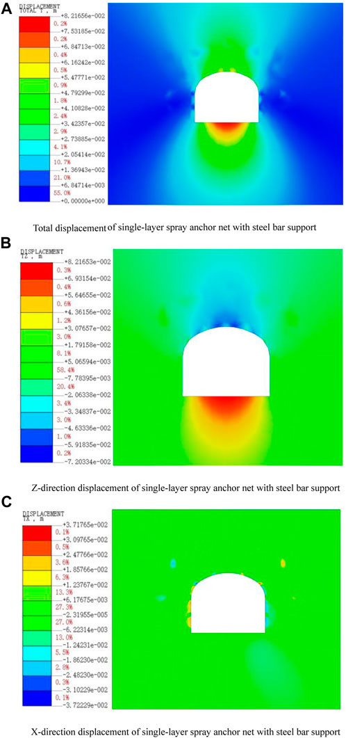
FIGURE 9. Deformation characteristics of surrounding rock under single-layer spray anchor mesh with steel bar support method.
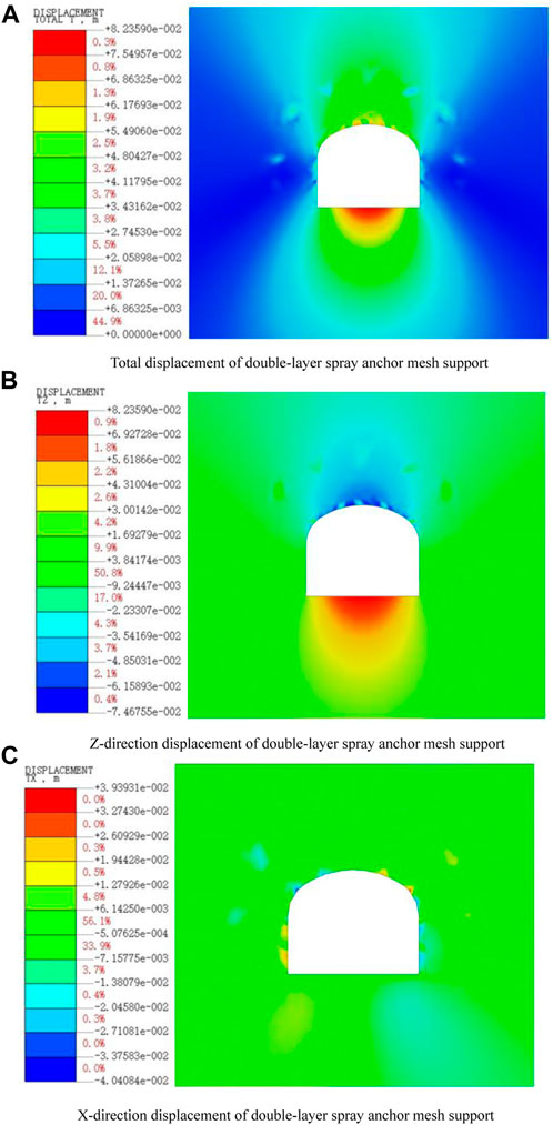
FIGURE 10. Displacement and deformation characteristics of surrounding rock supported by double-layer spray anchor mesh.
Upon analyzing Figures 9, 10, it is evident that the deformation of the surrounding rock differs under the influence of the two types of support. The total displacement map indicates an elliptical deformation pattern in the vertical direction. When employing double-layer spray anchor mesh support, the bottom of the surrounding rock exhibits prominent bulging, with a maximum deformation of 82.3590 mm. Furthermore, compared to single-layer spray anchor mesh support with steel bar reinforcement, there is a more noticeable settlement at the top of the surrounding rock. The inner bulge range on both sides of the tunnel’s surrounding rock is smaller than that of single-layer spray anchor mesh support with steel bars. However, both cases demonstrate greater displacement and settlement of the upper and lower surrounding rocks, with a reduced inner bulge range on both sides. This suggests that after tunnel excavation, the surrounding rock compresses and deforms from the periphery towards the center, placing significant pressure on the entire tunnel support structure. With the use of single-layer spray anchor mesh support with steel bars, the maximum bottom bulge measures 82.1656 mm, while the displacement and settlement of the surrounding rock roof are more evenly distributed. The inner bulge area on both sides of the surrounding rock is smaller. Consequently, it can be concluded that single-layer spray anchor mesh support with steel bar reinforcement exhibits superior deformation control on the tunnel’s roof and between the sidewalls compared to double-layer spray anchor mesh support.
6.3 Stress characteristics of roadway support anchor bolts
Figure 10 illustrates the stress characteristics of the anchor bolts supporting the surrounding rock in the roadway following excavation. Two different support methods were employed: double-layer spray anchor mesh support, and single-layer spray anchor mesh support with steel bar reinforcement.
Through the analysis of Figure 11, it can be seen that under the double-layer spray anchor mesh support method, the anchor rods are subjected to tensile force in all areas. The stress on both sides of the tunnel is significantly greater than that in other areas. There is a phenomenon of local anchor rod tension at the top of the tunnel, and there is a clear phenomenon of uneven tension at the top. After the application of secondary anchor rod support, the force acting on the anchor rods became more evenly distributed, and there was no significant phenomenon of local anchor rod tension. Furthermore, analysis reveals that the part of the anchor rod connected to the tray at its tail end experiences the smallest tensile force, while the tensile force at the top of the anchor rod is also lower. The closer the middle part is to the tail end of the anchor rod, the greater the tensile force. This is because, after tunnel excavation, the deformation of the surrounding rock closer to the free surface is greater. The distribution characteristics of the axial force on the anchor rod, after implementing the single-layer spray anchor net with steel bar support method, are similar to those observed with double-layer spray anchor net support. The most significant changes in axial force occur on both sides of the tunnel, with the axial force range extending deeper into the surrounding rock. However, the axial force on the anchor rod does not reach its maximum tensile strength.
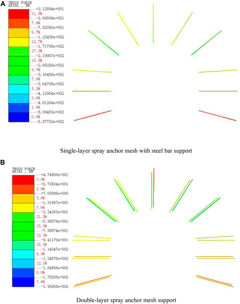
FIGURE 11. Stress characteristics of anchor rods under different support methods.
Additionally, Figure 11 illustrates that the axial force on the anchor rod under the single-layer spray anchor net with steel bar support method is lower compared to the double-layer spray anchor net support condition. This indicates that the steel bar can effectively reduce the tensile force on the anchor rod and uniformly distribute the axial force to the steel bar. Consequently, the distribution of axial force in the surrounding rock of the tunnel becomes more uniform. On the other hand, the double-layer spray anchor net support method only reduces the settlement of the surrounding rock through the axial force of the anchor rod, with the entire load borne by the anchor rod. This approach increases the risk of reaching the ultimate bearing capacity of the anchor rod, potentially resulting in tensile fracture. Therefore, employing the single-layer spray anchor mesh support with steel bar support method allows for more even stress transfer throughout the tunnel, reducing the occurrence of local stress concentration and mitigating the risk of tunnel collapse.
7 Field test
7.1 Experimental plan design
To thoroughly validate the experimental feasibility of the single-layer spray anchor net with steel bar support scheme in the crushing area of Yunnan Phosphate Mine, the layered connecting roadway of the 1890 m middle section of the 1# tape roadway was selected as the experimental site. The specific construction steps for the single-layer anchor spraying with steel reinforcement bar are as follows: using an anchor rod drilling machine, drill holes in the research section of the tunnel at intervals of 1000 mm × 2000 mm, and then clean the holes and install the anchor rods. After that, the holes are grouted, and the steel reinforcement bars are connected to the anchor rods through trays and bolts. The end of the steel reinforcement bars are subjected to a pre-tension force of 10 kN by using a washer and a nut. After the connection is completed, hang the metal mesh sheet and spray the surrounding rock of the tunnel with mortar to complete the one-time support. The steel reinforcement bars used in the experimental process were self-designed. They were bent and overlapped using a Φ10 mm steel reinforcement bar with a length of approximately 4044 mm and 2044 mm respectively. Additionally, a Φ8 mm steel reinforcement bar with a length of 80 mm was welded to provide fixation. After the excavation of the tunnel, a single-layer anchor mesh with steel reinforcement bar support system, spanning a length of 20 m, was employed on the left side of the connecting tunnel. On the right side of the connecting tunnel, a double-layer anchor mesh support system, also spanning a length of 20 m, was utilized to provide reinforcement. According to mathematical calculations, numerical simulation methods, and engineering practices, it is known that stress concentration is more likely to occur at the top and sides of the surrounding rock of deep tunnels. Moreover, the damage caused by stresses in these areas is also more significant. Therefore, this monitoring point is arranged in the middle of the 1890 m horizontal tape main roadway, with distances of 1 m and 4.4 m from the ground at the center and both sides of the roadway roof, respectively. Boreholes are drilled at a depth of 0.5 m for the installation of multi-point displacement meters to monitor the roadway roof and surrounding rock in real time. The layout of the on-site experimental support section and measurement points is illustrated in Figure 12.
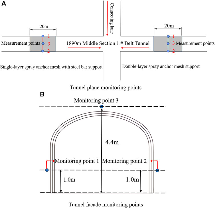
FIGURE 12. Layout of on-site support sections and measurement points.
7.2 Analysis of deformation monitoring results of tunnel surrounding rock
After more than 4 months of organizing and analyzing monitoring data from six boreholes in the monitoring section, a total of 12 sets of result data were monitored, revealing the displacement convergence across different monitoring sections of the tunnel. The curves depicting the variation of tunnel deformation convergence data over time, derived from the monitoring points, are illustrated in Figures 13, 14.
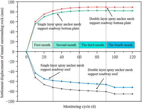
FIGURE13. Convergence of deformation of roadway roof under different support methods.
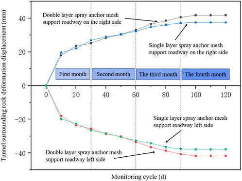
FIGURE 14. Convergence of deformation on both sides of the roadway under different support methods.
By observing Figures 13, 14, it can be observed that the deformation convergence of the roadway roof and both sides under different support methods is basically the same. The overall trend is that the deformation convergence of the surrounding rock is relatively large within 10 days after support and then gradually fluctuates within a certain range. As time goes on, the convergence of displacement deformation on the roof and both sides of the roadway gradually approaches a plateau. The settlement of the top plate of the roadway, supported by a single-layer spray anchor mesh and steel bars, gradually stabilized at 75.033 m. On the other hand, the bottom plate bulge settled at 82.165 mm. The deformation convergence displacement of the surrounding rock on the tunnel’s left side gradually stabilized at 37.835 mm, while that on the right side stabilized at 37.470 mm. The settlement of the roof of the roadway, supported by a double-layer spray anchor mesh, gradually stabilized at 84.199 mm, while the bottom heave stabilized at 85.255 mm. Similarly, the displacement and deformation of the surrounding rock on the tunnel’s left side gradually stabilized at 41.670 mm, whereas that on the right side of the tunnel stabilized at 41.756 mm. By comparing Figures 13, 14, it can be found that the control of tunnel deformation ability of single-layer spray anchor mesh and steel bar support is still better than that of double-layer spray anchor mesh support after losing one layer of spray anchor mesh support. This indicates that adding steel bar support after single-layer spray anchor mesh support can effectively resist the deformation ability of tunnel surrounding rock.
Through on-site experiments with different support methods, it was found that the use of single-layer spray anchor mesh and steel bar support is better than double-layer spray anchor mesh support under certain conditions. Whether it is from the settlement displacement of the top and bottom plates of the roadway or the displacement of the internal bulging on both sides of the roadway, the control effect of the single-layer spray anchor mesh and steel bar support on the deformation ability of the surrounding rock of the roadway is better than that of the double-layer spray anchor mesh support. Moreover, through long-term continuous observation of the surrounding rock of the supported roadway, it can be seen that the use of single-layer spray anchor mesh with steel bar support did not cause problems such as cracking of the sprayed concrete, fracture of the anchor rod, or delamination, fragmentation, and collapse of the roadway. The on-site experiments fully demonstrate that the use of single-layer spray anchor mesh with steel bar support can reduce the cost of roadway support and simplify the process steps. In the Yunnan Phosphate Mine area, using single-layer spray anchor mesh with steel bar support instead of double-layer spray anchor mesh support can completely meet the requirements of safe mining and achieve the maximization of support effect and economic benefits.
8 Conclusion
The 1# inclined shaft in the middle section of Yunnan Phosphate Mine at a depth of 1890 m is characterized by fractured surrounding rock. To minimize the cost of supporting the roadway surrounding rock and streamline the construction process, a comparative analysis was conducted using numerical simulation experiments and on-site tests. The study focused on comparing and analyzing the distribution characteristics of the plastic zone, the deformation characteristics of the tunnel surrounding rock, and the stress characteristics of tunnel support anchor bolts under two methods: double-layer spray anchor mesh support, and single-layer spray anchor mesh support combined with steel bar support. The following are the main conclusions derived from the study:
(1) Based on the analysis of numerical simulation results, it was found that the use of single-layer spray anchor mesh combined with steel bar support can effectively improve the plastic zone of the tunnel’s surrounding rock. The distribution of the plastic zone in the surrounding rock is more uniform, and the range of distribution is smaller. Moreover, this method has a better control effect on the convergence deformation of the surrounding rock displacement in the tunnel. It can also make better use of the mechanical properties of the anchor rod and steel bar. The bearing capacity of the anchor rod is uniformly transmitted to the steel bar, resulting in better control of the deformation effect of the surrounding rock.
(2) Based on the analysis of on-site monitoring data, the settlement of the top plate of the roadway supported by a single-layer spray anchor mesh with steel bars was found to be 75.033 mm. Additionally, the bottom bulge of the roadway floor was measured at 82.165 mm. The inner bulge measurements on the left and right sides of the tunnel are recorded as 37.835 mm and 37.470 mm, respectively. The settlement of the roof of the roadway, supported by a double-layer spray anchor mesh, is measured at 84.199 mm. Similarly, the bottom bulge of the roadway floor is recorded as 85.255 mm. Additionally, the inner bulges on the left and right sides of the tunnel are found to be 41.670 mm and 41.756 mm, respectively. These results indicate that the ability of single-layer spray anchor mesh combined with steel bar support to resist deformation of the surrounding rock in the roadway is significantly superior to that of double-layer spray anchor mesh support.
(3) Numerical simulation experiments combined with on-site testing have demonstrated that, under certain conditions, the support effect of the single-layer spray anchor mesh combined with the steel bar method is significantly superior to that of the double-layer spray anchor mesh support method. Furthermore, through long-term monitoring of the on-site support situation, it was observed that the use of single-layer spray anchor mesh combined with steel bar support did not cause any detachment, fragmentation, cracks, or fractures in the surrounding rock of the tunnel. This indicates that the use of single-layer spray anchor mesh combined with steel bar support instead of the original double-layer spray anchor mesh support is completely feasible and can meet the requirements for normal production on site.
While the research results pertain to gently inclined and thin phosphate rock, their applicability is not confined to this specific type. The support method has been thoroughly tested and can be implemented for various supports both domestically and internationally. It offers valuable guidance and reference for selecting cost-effective support schemes for tunnel surroundings, showcasing a high degree of generalizability. Following experimental research, the single-layer spray anchor mesh with steel bar support can find application in diverse fields including underground and rock tunnels, geotechnical engineering slopes, foundation pit support, and highway slopes. This method aims to augment the stability of rock masses or slopes, simultaneously reducing support costs and mitigating safety accidents.
Data availability statement
The original contributions presented in the study are included in the article/Supplementary material, further inquiries can be directed to the corresponding author.
Author contributions
MX: Conceptualization, Software, Validation, Writing–original draft, Writing–review and editing. XL: Conceptualization, Supervision, Writing–review and editing. JW: Conceptualization, Supervision, Validation, Writing–review and editing. MC: Conceptualization, Software, Supervision, Writing–review and editing. MW: Conceptualization, Data curation, Supervision, Writing–review and editing. SL: Conceptualization, Methodology, Validation, Writing–review and editing.
Funding
The author(s) declare financial support was received for the research, authorship, and/or publication of this article. The research work was funded by the Research Fund of National Natural Science Foundation of China (NSFC) (Grant No. 42277154), the project of Slope safety control and disaster prevention technology innovation team of “Youth Innovation Talent Introduction and Education Plan” of Shandong Colleges and universities (Grant No. Lu Jiao Ke Han (2021) No. 51); Guizhou Province Science and Technology Planning Project (Grant No. Guizhou science and technology cooperation support (2022) common 229), National Natural Science Foundation of Shandong Province of China (NSFC) (Grant No. ZR2022ME188), Jinan City “new university 20” research leader studio project (Grant No. 20228108), The State Key Laboratory of Coal Resources and safe Mining, CUMT (SKLCRSM22KF009), and Open Fund of National Engineering and Technology Research Center for Development and Utilization of Phosphate Resources of China (Grant No. funded the research work NECP 2022-04) and the Open Fund of Key Laboratory of Geological Hazards on Three Gorges Reservoir Area (China Three Gorges University), Ministry of Education (Grant No. 2022KDZ07), and Development and utilization of strategic mineral resources (Grant No. 2023YFC2907305).
Conflict of interest
Authors MW and SL were employed by Ynnan Phosphate Chemical Group Co., Ltd.
The remaining authors declare that the research was conducted in the absence of any commercial or financial relationships that could be construed as a potential conflict of interest.
The reviewer WZ declared a shared affiliation with the author JW to the handling editor at time of review.
Publisher’s note
All claims expressed in this article are solely those of the authors and do not necessarily represent those of their affiliated organizations, or those of the publisher, the editors and the reviewers. Any product that may be evaluated in this article, or claim that may be made by its manufacturer, is not guaranteed or endorsed by the publisher.
References
Cai, B., Yu, Y., and Wu, X. M. (2001). The relationship between the "Engineering Rock Mass Classification Standard" and the Q classification method and RMR classification method, as well as the estimation of deformation parameters. J. Rock Mech. Eng. 1, 1677–1679.
Chen, N. Q. (2023). Research on the evaluation of anchor mesh support effect in roadways based on surrounding rock grade. Min. Res. Dev. 43 (07), 67–73. doi:10.13827/j.cnki.kyyk.2023.07.028
Gao, Y., Du, C. X., and Zhang, G. Q. (2023). Determination of rock mechanics parameters based on Hoek Brown criterion. Compr. Util. fly ash 37 (05), 7–12. doi:10.19860/j.cnki.issn1005-8249.2023.05.002
Han, H. W. (2023). Comparison of support effects of different anchor rod support parameters. Mech. Manag. Dev. 38 (09), 27–29. doi:10.16525/j.cnki.cn14-1134/th.2023.09.011
Han, S., Wang, W. J., Dong, E. Y., and Peng, G. (2023). Research on the butterfly-shaped plastic zone control method of tunnel surrounding rock based on support interference. J. Min. Saf. Eng. 40 (04), 743–753. doi:10.13545/j.cnki.jmse.2022.0669
Hoek, E., and Marinos, P. (2007). A brief history of the development of the Hoek-Brown failure criterion. Soils Rocks 30 (2), 85–95. doi:10.28927/sr.302085
Hou, D., Xu, M. C., Li, X. S., Wang, J. W., Wang, M. L., and Li, S. J. (2023a). Optimization of mining methods for deep orebody of large phosphate mines. Front. Built Environ. 9, 1282684. doi:10.3389/fbuil.2023.1282684
Hou, D., Xu, M. C., Li, X. S., Wang, J. W., Wang, M. L., and Li, S. J. (2023b). Study on filling mining technology for gently inclined thin to medium thick phosphorus deposits. Front. Earth Sci. 11, 1254509. doi:10.3389/feart.2023.1254509
Huang, J., Li, S. J., Xia, G. Y., Wang, M. L., Zhang, B., and Liu, Y. H. (2022). Research on underground mining methods for gently inclined medium thick ore bodies in Kunyang Phosphate Mine No. 2. Mod. Min. 38 (07), 45–50+55.
Kang, Y. S., Liu, Q. S., Liu, B., Zhu, Y. G., Li, X., and Wang, S. (2023). Exploration of step-by-step combined support technology for precise intervention of surrounding rock structure in deep rock tunnels. J. Rock Mech. Eng. 42 (11), 2682–2693. doi:10.13722/j.cnki.jrme.2023.0035
Li, X. S., Li, Q. H., Wang, Y. M., Liu, W., Hou, D., Zheng, W., et al. (2023). Experimental study on instability mechanism and critical intensity of rainfall of high-steep rock slopes under unsaturated conditions. Int. J. Min. Sci. Technol. 33, 1243–1260. doi:10.1016/j.ijmst.2023.07.009
Liu, Y. H. (2022). Prediction of water inflow in underground mining pits of Kunyang Phosphate Mine No. 2. Chem. Mineral. Geol. 44 (01), 78–85.
Ma, N. J., Ma, H. Y., Wang, Y. W., and Lv, K. (2023). The principle of deep deformation roadway support and flexible anchor cable support technology. J. Min. Saf. Eng. 40 (05), 957–964. doi:10.13545/j.cnki.jmse.2023.0339
Qin, S. L., Zhao, X. D., Hu, Y. Y., Ouyang, X. X., and Zhang, W. (2023). Deformation characteristics and control techniques of surrounding rock in deep hard rock tunnels. Metal. Mines 12, 9–13. doi:10.19614/j.cnki.jsks.202312002
Ren, J. W., Zuo, Y. J., Lin, J. Y., Chen, Q. G., and Jin, K. Y. (2023b). Stability evaluation of surrounding rock in tunnels with weak interlayers based on improved uncertain measures. Min. Metallurgy Eng. 43 (04), 39–43+47.
Ren, J. W., Zuo, Y. J., Lin, J. Y., Chen, Q. G., Jin, K. Y., and Rong, P. (2023a). Research on the influence of weak interlayers on the stability of surrounding rock in deep tunnels of gold mines. Min. Res. Dev. 43 (09), 127–133. doi:10.13827/j.cnki.kyyk.2023.09.015
Ren, Z. M. (2023). The deformation of surrounding rock and the combined control technology of anchor injection and spraying in the interlayer roadway of Jinneng Coal Industry. Shandong Coal Technol. 41 (08), 56–58.
Tang, J. H., Wu, J. A., and Yu, W. J. (2023). Research on surrounding rock control technology for small spacing and large section tunnel groups. Min. Res. Dev. 43 (09), 84–90. doi:10.13827/j.cnki.kyyk.2023.09.022
Wang, T. C., Ming, S. X., and Mao, S. L. (2016). Research on the support mechanism of soft rock tunnels based on the theory of confining pressure restoration and reinforcement. Nonferrous Met. Min. Part. 68 (01), 94–97.
Yang, N., and Zhao, M. X. (2023). Huang Yubing Stress distribution law and support optimization of surrounding rock in deep rectangular tunnels. J. Min. Rock Form. Control Eng. 5 (06), 43–52. doi:10.13532/j.jmsce.cn10-1638/td.2023.06.001
Yang, X. G., and Chen, J. (2023). Research and application of multiple support technologies for rapid excavation of rock tunnels in Fangezhuang Coal Mine. Coal Technol. 42 (10), 91–95. doi:10.13301/j.cnki.ct.2023.10.020
Yang, Y. P., Yang, Y. L., Mu, Y. S., and Han, B. (2018). Research and application of deep high-stress fractured rock roadway support technology in Jinchuan mining area. China Min. 27 (11), 99–103.
Keywords: support cost, double-layer spray anchor net, single-layer spray anchor net, steel bar, settlement, monitoring data
Citation: Xu M, Li X, Wang J, Cao M, Wang M and Li S (2024) Application research on low cost support method for surrounding rock of broken section roadway in phosphate mine area. Front. Earth Sci. 12:1372506. doi: 10.3389/feart.2024.1372506
Received: 18 January 2024; Accepted: 15 February 2024;
Published: 06 March 2024.
Edited by:
Bin Gong, Brunel University London, United KingdomReviewed by:
Wen Zhong, Jiangxi University of Science and Technology, ChinaXiaofei Jing, Chongqing University of Science and Technology, China
Yanlong Chen, China University of Mining and Technology, China
Copyright © 2024 Xu, Li, Wang, Cao, Wang and Li. This is an open-access article distributed under the terms of the Creative Commons Attribution License (CC BY). The use, distribution or reproduction in other forums is permitted, provided the original author(s) and the copyright owner(s) are credited and that the original publication in this journal is cited, in accordance with accepted academic practice. No use, distribution or reproduction is permitted which does not comply with these terms.
*Correspondence: Jiawen Wang, eG1jeXlkZDIwMjJAMTI2LmNvbQ==