 Guanzhong Wu1,2,3
 Shaochi Peng
94% of researchers rate our articles as excellent or good
Learn more about the work of our research integrity team to safeguard the quality of each article we publish.
Find out more
ORIGINAL RESEARCH article
Front. Earth Sci., 20 March 2024
Sec. Geohazards and Georisks
Volume 12 - 2024 | https://doi.org/10.3389/feart.2024.1370672
This article is part of the Research TopicRisk Assessment, Stability Monitoring, and Safe Design for Deep Rock EngineeringView all 20 articles
The investigation of stress field and plastic zone distribution at the closed crack tip provides a fundamental basis for failure analysis and life prediction of geotechnical materials. Closed crack is a common crack in geotechnical materials. Studying the distribution of stress field and plastic zone at the tip of closed crack can provide theoretical basis for stability evaluation of geotechnical structures. In this study, we employ the superposition principle to obtain complex function solutions for the stress field and displacement field at the crack tip. Furthermore, we analyze the plastic zone distribution at the crack tip based on the Mohr Coulombs criterion. We investigate how factors such as crack angle, confining pressure, and material properties influence the stress field, displacement field, plastic zone size, and crack propagation direction. Our results demonstrate that this method effectively characterizes the distribution of stress field and displacement field at closed crack tips. Moreover, we elucidate that wing cracks are primarily formed due to tension-shear coupling effects. The solutions for the stress field and displacement field at the crack tip are obtained using the superposition principle. The distribution of the plastic zone at the crack tip is analyzed based on the M-C (Mohr-Coulomb) criterion. Subsequently, an analysis is conducted to investigate the influence of crack angle, confining pressure, and material properties on stress field, displacement field, plastic zone, and crack propagation direction. Lower crack angles and higher confining pressures effectively suppress slip between crack surfaces by reducing tension-shear coupling effects and inhibiting wing foil crack development. The results further indicate that the rock cohesion and internal friction angle exert negligible influence on the stress field, displacement field, plastic zone shape at the crack tip, as well as the growth direction of new cracks. The results demonstrate the effective representation of stress field and displacement field at the closed crack tip using this method. The stress distribution at the crack tip reveals that the tension-shear coupling effect primarily contributes to wing crack formation. Lower crack angles and higher confining pressures effectively suppress surface slip, reduce tension-shear coupling effects, and inhibit wing crack propagation. Furthermore, material properties do not influence the crack propagation angle, stress field, or displacement field.
• A method is proposed for calculating the stress field and the angle of crack extension at the tip of a closed crack.
• The tensile-shear coupling effect is shown to be the main cause of wing crack initiation.
• The crack propagation direction is unaffected by changes in cohesion and internal friction angle.
• Stress invariance and displacement invariance exist around closed cracks.
The Jiaopingdu Ferry serves as a crucial crossing point for the Red Army over the Jinsha River, embodying immense significance in upholding our national spirit. Situated within the inundation area of Wudongde Reservoir, both the ferry and cave site have been submerged to depths ranging from 60 to 90 m following the completion and operation of Wudongde Power Station. The slope of the cave site primarily consists of weakly consolidated gravel soil, characterized by numerous cracks. These cracks induce stress concentration, leading to a deterioration in mechanical properties and subsequently reducing site stability. Without effective protective measures, there is a risk of flooding, destruction or even collapse at this location. Therefore, studying stress field distribution and plastic zone behavior near crack tips can provide essential insights for designing an optimal protection plan for this site.
Fracture mechanics is an important branch of solid mechanics. The study of crack propagation modes and material failure modes has been a hot topic in the industry (Wang et al., 2021a; Ju et al., 2022). The study of the stress field at the crack tip is crucial for failure analysis. However, most of the existing research results focus on open cracks and do not consider the contact between crack surfaces (Zhou et al., 2021). In geotechnical engineering, structures are often subjected to compressive loading, which can result in closed cracks. This hinders the application of fracture mechanics in geotechnical engineering (Ming et al., 1996; Zhu et al., 1997; Chen et al., 2003). Therefore, it is of great theoretical value to study the stress field at the crack tip of closed cracks. This will allow for further analysis of the distribution law of the plastic zone at the crack tip and prediction of the expansion direction of new cracks. The aforementioned statement provides a theoretical foundation for the design and construction of the Jiaopingdu reinforcement project, thereby offering novel insights into the failure mechanisms of geotechnical materials.
In terms of theoretical research, scholars began their studies by examining the behavior of an infinitely large flat plate under uniform tensile stress. They developed fruitful calculation methods, including the Green’s function method (Erdogan et al., 1974; Hasebe et al., 2003) and the Legendre series expansion method (Isida, 1966; Isida, 1970), among others. Subsequently, the interactions between multiple holes and multiple cracks gradually became a popular field of research. For example, Tang (Renji and Yinbang, 1986) calculated the stresses resulting from these interactions by applying an artificial load on the surfaces of the cracks and considering the strength factor of the round holes. This approach led to the derivation of a system of Cauchy-type integral equations. Finally, the displacement discontinuity method (Yan and Miao, 2012), the dislocation density method (Hu et al., 1993), and the boundary integral method (Wang and Chau, 1997) were introduced one after another. For example, Wei et al. (Yi et al., 2020) proposed a formula for calculating the stress intensity factor of multiple holes and cracks under the influence of far-field stresses and surface stresses using the superposition principle. Peng (Peng et al., 2022) calculated the stress intensity factor at the tip of a closed co-linear crack, but the physical significance of the coefficients was not explained, and further analysis of the stress and displacement fields at the crack tip was missing.
Due to the compressive loading in the far field, there is contact between the surfaces that are cracked. This causes some difficulties in stress analysis at the crack tip. In this regard, scholars have gradually adopted Computer-Aided Engineering (CAE) methods for further research. For example, Dolbow (Dolbow et al., 2001) and Khoei (Khoei and Nikbakht, 2007) utilized different iterative algorithms to investigate the problem of contact friction. In addition, Elguedj (Elguedj et al., 2007) employed the extended finite element method in conjunction with augmented Lagrange multipliers to simulate the expansion process of contact friction cracks. It provides a basis for stress analysis and extension prediction of closed cracks.
In the theoretical study of the plastic zone at the crack tip, scholars firstly explored the distribution of the plastic zone at the crack tip in pure Mode I cracks (Xin et al., 2010; Ban and Yao, 2023). It was shown that in Mode I cracks, the plastic zone at the crack tip was distributed in a “butterfly” pattern. Then, the distribution pattern of the plastic zone at the crack tip in pure Mode II cracks was gradually explored. For example, Peihua (Jing et al., 2003) investigated the evolution of the crack tip plastic zone under different criteria, and proposed that the distribution of the crack tip plastic zone has a complex dependence on Poisson’s ratio under plane strain. As the research in this field continues to advance, important breakthroughs have also been made in the plastic zone distribution of composite cracks (Sousa et al., 2013; Huang, 2023). For example, Huang (Huang, 2023) proposed an analytical solution for the plastic zone of composite cracks and derived a linear relationship between the constraint parameter and fracture toughness.
Researchers in the field of geotechnical engineering are more interested in experimental aspects than in theoretical and simulation studies. Acoustic emission experiments [(Jiang et al., 2021; Liu et al., 2021; Wu et al., 2021)] and nuclear magnetic resonance (NMR) methods (Bi et al., 2023) are commonly used experimental techniques. The effects of various environmental factors, such as chemical corrosion (Pan et al., 2022), temperature (Xiao et al., 2021), and filling state [(Zhang et al., 2021; Sharafisafa et al., 2021)], have been studied in relation to crack propagation modes. Meanwhile, the number [(Wang et al., 2021b; Yang et al., 2021)] and Mode (Ma et al., 2022) of cracks have also been studied more extensively.
The aforementioned studies provide a simulation and experimental foundation for stress analysis and growth prediction of enclosed cracks. However, there is a lack of theoretical explanation in mechanics. Therefore, it is particularly urgent to study the stress field and plastic zone distribution at the tip of closed cracks in order to explain the cause of crack extension. In this study, firstly, based on the principle of superposition, the bidirectional compressive load is equivalent to the combination of three individual load effects. The stress function applicable to the single load is constructed, and then the stress and displacement fields at the crack tip are solved. The Mohr Coulombs criterion (M-C criterion) is used to calculate the plastic zone at the crack tip. The minimum plastic radius theory is used to calculate the crack extension angle, which reveals the reason for the formation of the wing crack. Finally, the effects of crack angle, confining pressure magnitude, and material properties on the stress field, displacement field, and plastic zone are analyzed. To establish a theoretical foundation for the analysis of failures in geotechnical structures.
To calculate the stress field at the closed crack tip caused by bidirectional compressive loading, the superposition principle can be applied. This principle involves calculating the stress distribution at the crack tip for each individual loading condition and then algebraically combining the stresses from each loading to determine the actual stress distribution at the crack tip. A schematic representation of the superposition principle is shown in Figure 1.
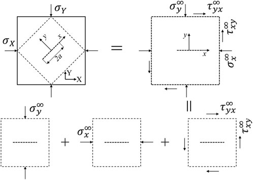
Figure 1. Schematic diagram illustrating the superposition principle.
In the figure,
An infinite plate containing a central crack is subjected to compressive loading at both ends, as shown in Figure 1. A relative coordinate system, xoy, is established at the center of the crack, with the x-axis aligned in the same direction as the length of the crack. In the relative coordinate system xoy, the rectangular cell located far from the crack is chosen as the subject of study. In this case, the original problem can be considered as a compression-shear combined loading problem for a horizontally cracked plate. Among them, the far-field stress can be expressed as Eq. 1.
Where,
According to the principle of superposition, the original problem can be further subdivided into three types of stress effects: vertical load, parallel load and pure shear.
When a cracked surface is subjected to vertical loading, there is normal contact and no relative sliding on the cracked surface. The stress boundary conditions can be expressed as Eq. 2.
Where,
From the stress boundary conditions, it can be observed that when subjected to compressive loading perpendicular to the crack surface, the stress field near the crack remains unchanged and the stresses near the crack are uniform throughout.
Under parallel compressive loading, the crack surface tends to open, and the crack develops into a pure Mode I crack. The stress boundary conditions are given in Eq. 3.
In the case of a pure Mode I crack, a stress function of the following form will be chosen.
Where,
Two partial derivatives of Eq. 4 yield the corresponding stress components. The expression for the stress component at the crack tip is given by:
A new physical quantity is introduced to describe the position of an arbitrary point relative to the crack tip. As shown in Eq. Eq. 6.
The function
Introduction of a stress intensity factor expression for Mode I cracks.
Note: The stress intensity factor mentioned here refers to the stress intensity factor for the parallel loading condition, not the actual stress intensity factor.
Combining Eqs 5, 7, 8 gives an expression for the stress component in terms of the stress intensity factor.
The stress along the crack plane direction is consistently negative under parallel loading, as indicated by Eq. 9. This results in sliding between the crack surfaces, known as shear effect. Perpendicular to the crack, stress distribution depends on the position of any point at the crack tip. Stress in opposite directions is generated on both sides of the crack, causing significant separation between the crack surfaces, referred to as stretching effect. In summary, when subjected to transverse compression load, tensile stress concentration occurs at the crack tip while joint tensile shear effect arises in non-crack plane direction.
Under pure shear loading, relative slip occurs at the crack surface, causing the crack to develop into a pure Mode II crack. For pure Mode II cracks, Eq. 10 was chosen as the stress function.
Where,
The complex function expression for the stress component is obtained as follows.
Introduction of a stress intensity factor expression for Mode II cracks.
The simplified stress components were obtained from Eq. 12.
According to the principle of superposition, the crack tip stresses under the three loads are algebraically added to obtain the crack tip stress field under bidirectional compressive loading.
The stress components calculated by Eq. 14 form the stress field at the tip of the closed crack.
Assuming that the crack tip satisfies the assumptions of small deformation and elasticity, the relationship between displacement and stress can be derived from the geometric and physical equations as shown Eq. 15.
Where,
Combined with Eq. 5, the expression for the complex function of displacement under parallel compressive loading can be obtained as shown Eq. 16.
Combined with Eq. 11, the expression for the complex function of displacement under shear loading can be obtained as shown below Eq. 17.
By combining equations. In Eqs 9, 13, the complex function form is replaced by the polar coordinate form. The expression for the displacement component is obtained as Eqs 18, and 19.
According to the principle of superposition, the distribution of the displacement field at the tip of a closed crack can be obtained by algebraically adding the displacement components under each individual load.
To verify the correctness of Eq. 14 for calculating the stress field at the crack tip. Finite element software was used to validate the problem. In the validation example, the crack angle ranges from 0° to 90°. And

Figure 2. Comparison of finite element and analytical solutions. (A)
As the crack angle increases, the stress along the crack direction continuously increases, while the stress perpendicular to the crack direction continuously decreases. Additionally, the shear stress at the crack tip is symmetrically distributed at an angle of 45°. The evolution law of the stress field at the crack tip with respect to the crack angle is consistent with that of the stress evolution law in the oblique section. This consistency proves the correctness of the equation in describing the evolution of stress. Meanwhile, the discrepancy between the analytical solution and the CAE solution is small, which confirms the accuracy of the equation in describing the magnitude of stress. In summary, the accuracy of the calculation method used in the thesis has been verified.
From the analysis of the stress field at the crack tip, it can be observed that the stress-strain increases infinitely and a singularity occurs at the crack tip. For a cracked body under actual loading conditions, it is inevitable that a plastic zone will appear near the crack tip as the external load increases. To investigate the distribution law of the plastic zone at the crack tip, this section solves the same problem using the Von Mises criterion and the M-C criterion.
In the example of comparative analysis of the plastic zone, the crack angle is assumed to be 45°, and the crack half-length is assumed to be
The principal stress at the crack tip is a crucial physical parameter for analyzing the plastic zone. To study the distribution of the plastic zone at the crack tip, it is necessary to first solve for the principal stress at the crack tip. For the planar problem. The formula for calculating the principal stress is given in Eq. 20.
The calculation equation is simplified by Eq. 21.
Where, A represents the average stress coefficient, B represents the bias stress coefficient, and C represents the shear stress coefficient.
A simplified expression for the principal stresses is obtained as shown below.
Substituting the obtained principal stresses into the corresponding yield criterion yields the corresponding plastic zone distances.
The Von Mises criterion is derived from the strain energy density, which closely matches experimental results and is a commonly used yield criterion in the mechanics of materials. The expression is given below.
Where,
Substituting Eq. 23 into Eq. 22 to get Eq. 24.
To simplify the calculation. The term containing
Where,
The M-C criterion is a commonly used damage criterion in geotechnical engineering that effectively reflects the mechanical response of brittle materials, such as rock and soil, when subjected to compression. The criterion expression is shown below.
Where,
Substituting Eq. 26 into Eq. 22. The yield equation is obtained as Eq. 27.
Again, to simplify the calculations, the term containing
Where,
To compare the variability in the distribution of the plastic zone at the crack tip between the two codes. The same problem is analyzed using two plastic zone formulas. Take
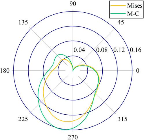
Figure 3. Comparison of the two guidelines.
In the first quadrant, the difference between the Von Mises criterion and the M-C criterion is small. The crack extension angles are mostly concentrated in the first quadrant. This indicates that the prediction of crack extension by the two codes tends to agree. The crack extension angle has little correlation with material properties. In the remaining quadrants, the plastic zone has a smaller radius for the Von Mises criterion, indicating that the Von Mises criterion is more aggressive, while the M-C criterion is more conservative when assessing material properties under the same conditions. Meanwhile, the shapes of the two plastic zones are more similar, but the M-C criterion is more pronounced at the extremes, indicating a higher level of stress sensitivity.
As the distance from the crack tip increases, the stress concentration phenomenon gradually diminishes and decreases. Therefore, it is more reasonable to select the angle of the smallest plastic radius as the angle for crack extension.
The minimum plastic radius determination rule is used to predict the direction of crack propagation. The crack propagation Angle is calculated by Eq. 29.
Where,
In the example analyzed in the plastic zone, the direction of expansion for a 45° crack is shown in Figure 4.
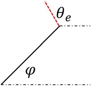
Figure 4. Schematic of crack expansion direction.
As can be seen in Figure 4, the crack extension is not in the same direction as the crack. There is a specific angle between the new crack and the old crack. This crack is called a wing crack, which is a common type of crack in geotechnical experiments.
Pure Mode I cracks should propagate perpendicular to the direction of tensile stress. Pure Mode II cracks propagate along the direction of the crack. The analysis shows that the actual crack extension is somewhere in between. This indicates that the wing crack is a result of the combined tensile-shear effect rather than the influence of a single load.
In order to investigate the effect of crack angle on the stress field, displacement field, plastic zone, and the angle of new crack extension at the crack tip. Five examples with crack angles of 0°, 30°, 45°, 60°, and 90°, and a crack half-length of
Five examples were analyzed, and the variation curve of the stress component at the crack tip with angle was obtained, as shown in Figure 5.
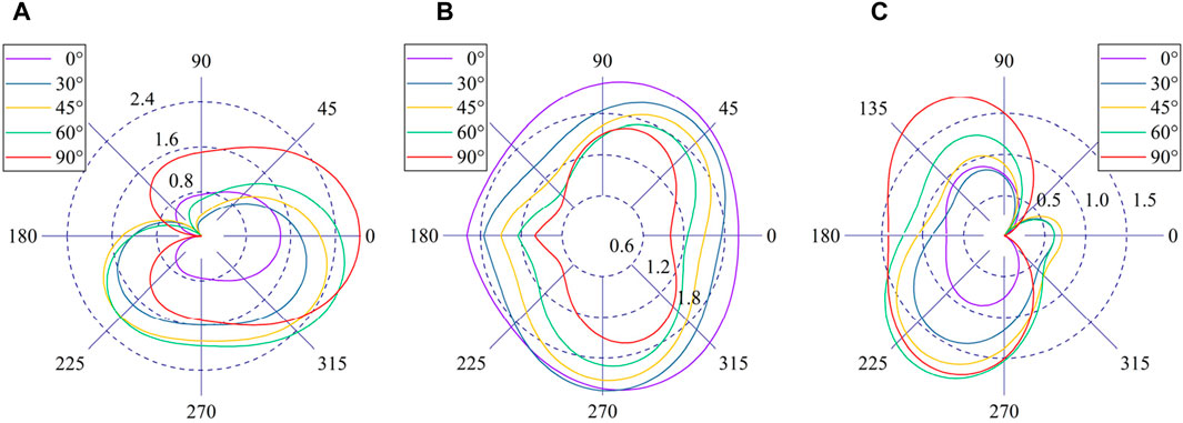
Figure 5. Variation curve of stress field with crack angle. (A)
As the crack angle increases, the stress along the x-axis in the direction of the crack gradually increases. Meanwhile, the stress field between a 0° crack and a 90° crack has a similar shape. It is symmetrically distributed along the x-axis and has a maximum value in the direction of the crack. This is because the cracks at both angles are exposed to a single type of stress and are not subjected to shear stress. The crack is a pure Mode II crack at 0° and a pure Mode I crack at 90°. While the other angled cracks are subjected to shear stress, the maximum stress does not occur along the crack direction but at an angle to the crack direction.
For the stress on the y-axis, the stress level continues to decrease as the crack angle increases. This is because
For shear stress, the level of shear stress gradually increases as the crack angle increases. In the direction parallel to the crack, the shear stress of a 0° crack and a 90° crack in Eq. is maintained at 0. Therefore, in practice, ensuring a perpendicular relationship between the crack and the main compressive load can effectively inhibit crack extension.
Five examples were analyzed, and the curve of the displacement component of the crack tip with respect to the crack angle was obtained, as shown in Figure 6.
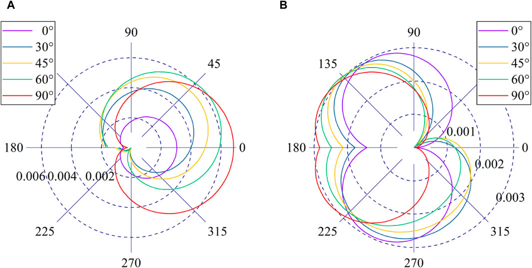
Figure 6. Variation curve of displacement field with crack angle. (A)
In the x-direction displacement, the crack surface experiences shear stresses, leading to uneven displacements above and below the crack surface, and causing the crack surface to slide relative to each other. This is depicted in the figure as a graphical non-closure. The 0° crack and the 90° crack remain closed as they are not subjected to shear stress. In the direction along the crack, the displacement in the x-axis gradually increases as the crack angle increases. This is because the stress level in the x-axis gradually increases as the crack angle increases.
The y-axis displacement exhibits a distinct pattern of change. Along the direction of the crack, the displacement along the y-axis reaches its maximum at a 45° crack distribution and is symmetrically distributed with respect to the axis of symmetry at 45°. Near the crack tip, the displacement increases as the crack angle increases. This indicates that the concentration of tensile stress at the crack tip becomes more pronounced as the angle of the crack increases. It is worth noting that the y-axis displacement has higher values in the second quadrant than in the fourth quadrant. This implies that the crack tends to propagate more towards the boundary direction when the stress environment is uniform.
To further analyze the rule of change in sliding displacement of the crack surface with respect to crack angle. The relative displacement of the upper and lower surfaces of the crack is obtained, as shown in Figure 7.
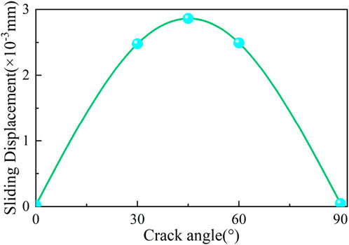
Figure 7. Crack surface slip curve.
From Figure 7, it can be observed that the sliding displacement between the surfaces of the crack reaches its maximum value when the crack angle is 45°. Furthermore, this displacement is symmetrically distributed along the 45° angle, which serves as the symmetry axis. This phenomenon further confirms that ensuring a perpendicular relationship between the crack and the main compressive load can effectively inhibit crack extension.
Five examples were analyzed, and the curve of the plastic zone at the crack tip was obtained as a function of crack angle. This is shown in Figure 8A. The curves for the plastic zone distance along the crack direction and perpendicular to the crack direction are obtained, as shown in Figure 8B.
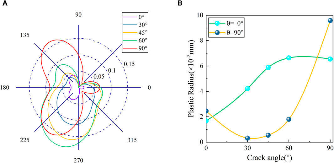
Figure 8. Influence of crack angle on the plastic zone. (A) Distribution of plastic zones. (B) Plastic Zone Distance Curves.
The shape of the plastic zone is similar for 0° and 90° cracks, but it is much larger for 90° cracks compared to 0° cracks. Except for these two types of angular cracks, the plastic zone increases as the crack angle increases.
In the y-direction, as the crack angle increases, the plastic zone exhibits a decreasing and then increasing pattern of change. In the x-direction, as the angle of the crack increases, the change rule demonstrates a gradual increase. This is essentially in line with the rule of displacement change.
Five cases were analyzed to obtain the new crack extension scheme shown in Figure 9. The crack extension angles are obtained as shown in Table 1.
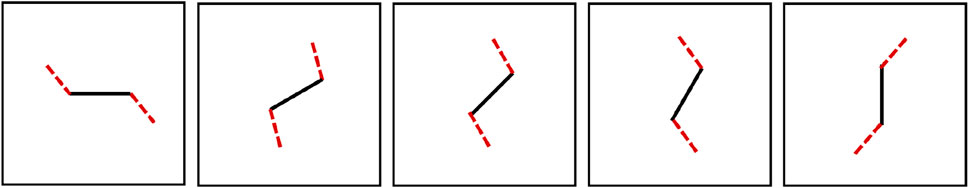
Figure 9. Schematic of crack extension angle.
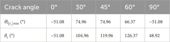
Table 1. Crack expansion angle.
The crack propagation in the wing can be clearly seen in the figure. It is noteworthy that both the 0° crack and the 90° crack, also known as the wing cracks, are equally generated and have the same minimum plastic zone distance angle. For the 90° crack, the crack tip experiences a significant concentration of tensile stress, while the M-C criterion favors shear damage. Therefore, in practice, the crack should be more vertical.
The magnitude of the confining pressure is equally important for crack propagation. For example, let’s consider a 45° crack with a crack half-length of
The variation of the crack tip stress field with confining pressure is shown in Figure 10.
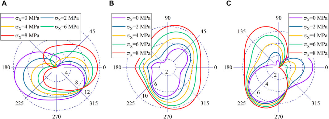
Figure 10. Stress field distribution curve with confining pressure. (A)
For the x-axis stress, when the confining pressure equals the vertical pressure, the stress is symmetrically distributed along the crack. The stress along the direction of the crack gradually increases as the confining pressure increases. The stress near the crack tip continuously decreases. The stress curves have the same phase in quadrant 4 compared to the same point. This shows that there is an invariant stress around the crack that is solely influenced by the vertical pressure and not by the confining pressure.
By combining Eqs 9, 13, it is deduced that the relationship between the direction angle of stress invariant and the crack angle can be expressed by the Eq. 30.
The stress invariants reveal the existence of a specific location near the crack tip, where the stress parallel to the crack plane is solely influenced by the vertical load and independent of lateral pressure. Moreover, this position is correlated with the orientation of the crack angle. Notably, when the crack inclination is 0°, this position aligns with 180°; whereas for a crack angle of 90°, it corresponds to 0° direction.
For the y-axis stress, the stress level gradually increases as the confining pressure increases. At the same time, the stress gradually converges to a symmetrical direction and the curve transition becomes smoother.
When the confining pressure is equal to the vertical pressure, the level of shear stress gradually increases with the increase in angle. In addition, the shear stress follows a pattern of initially decreasing and then increasing with the increase in angle. Meanwhile, within the range of ±45°, the shear stress value gradually decreases with an increase in confining pressure. Outside this range, the shear stress increases as the confining pressure increases. In the fourth quadrant, the shear stress remains constant.
The variation of the crack tip displacement field with confining pressure is shown in Figure 11.
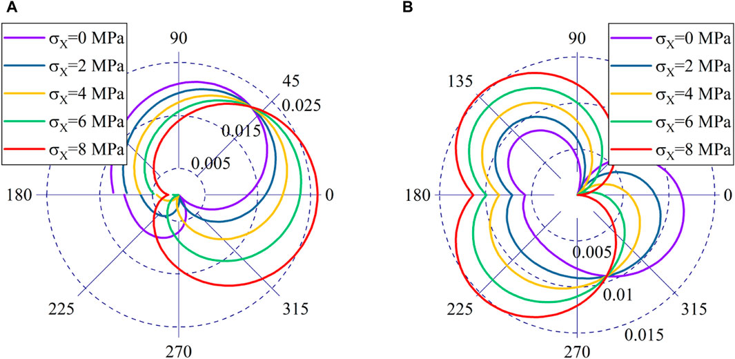
Figure 11. Displacement field distribution curve with confining pressure. (A)
The displacements in the x direction also show a break point, indicating relative sliding of the cracked surface. It is worth noting that, just as the stress curves intersect at the same point in quadrant 4, the x displacements intersect at the same point in quadrant 1. This indicates the presence of an invariant displacement around the crack which is related only to the vertical pressure and not to the magnitude of the confining pressure.
The Eq. 31 for the displacement invariant can be derived based on Eq. 18.
Similar to the stress invariant, when the crack inclination is held constant, there exists a specific position at the crack tip where the displacement parallel to the crack plane remains unaffected by lateral pressure. Notably, for a crack inclination of 0°, this position lies in the direction of 180°; whereas for a crack angle of 90°, it lies in the direction of 0°. Remarkably, this position coincides with that identified by the stress invariant.
The rule for changing the y-direction displacement is the same as that for the shear stress. In the range of ±45°, the displacement in the y-direction gradually decreases as the confining pressure increases. At the same time, the displacement is constant in the fourth quadrant.
To further investigate the impact of the confining pressure magnitude on the sliding displacement of the cracked surface, we obtained the indicated sliding displacements above and below the crack, as shown in Figure 12.
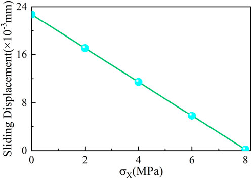
Figure 12. Crack surface slip curve with confining pressure.
It can be observed from the figure that the sliding phenomenon between the crack faces decreases linearly with the increase in confining pressure. This indicates that the confining pressure can effectively prevent the relative sliding of the crack faces.
The variation curve of the plastic zone at the crack tip with confining pressure is shown in Figure 13A. The curves depicting the distance of the plastic zone along the crack direction and perpendicular to the crack direction in relation to the confining pressure are presented in Figure 13B.
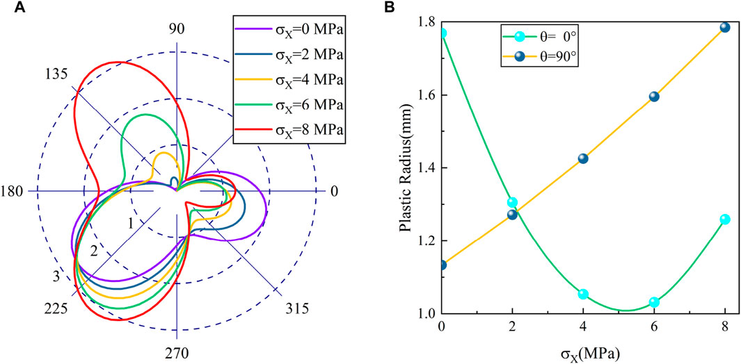
Figure 13. Influence of confining pressure on the plastic zone. (A) Distribution of plastic zones. (B) Plastic Zone Distance Curves.
The plastic zone at the crack tip exhibits an opposite change pattern compared to the crack angle. As the confining pressure increases, the plastic distance along the crack direction follows a pattern of initially decreasing and then increasing. And in the direction perpendicular to the crack, the plastic zone increases with the increase in confining pressure. The main reason is that as the confining pressure increases, the overall stress level in the plate also increases significantly. This results in a more pronounced stress concentration at the crack tip, which in turn leads to an expansion of the plastic zone.
The variation of the crack extension angle with confining pressure is shown in Figure 14.
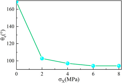
Figure 14. Variation curve of crack extension angle with confining pressure.
As the confining pressure increases, the angle of crack extension gradually decreases and approaches 90°. This is because as the confining pressure increases, the sliding between the surfaces of the crack weakens, and the tensile-shear coupling effect gradually diminishes. Therefore, the crack extension tends to be closer to the point of tensile damage.
To investigate the effect of rock material properties on the plastic zone. Keeping the other variables constant in the analyzed example, the angle of internal friction and cohesion were varied. This is because the change in material properties does not affect the stress field at the crack tip. For a given modulus of elasticity and Poisson’s ratio, the stress field and displacement field at the crack tip remain unchanged. The curves depicting the impact of the internal friction angle and cohesion on the radius of the plastic zone are obtained, as illustrated in Figure 15.
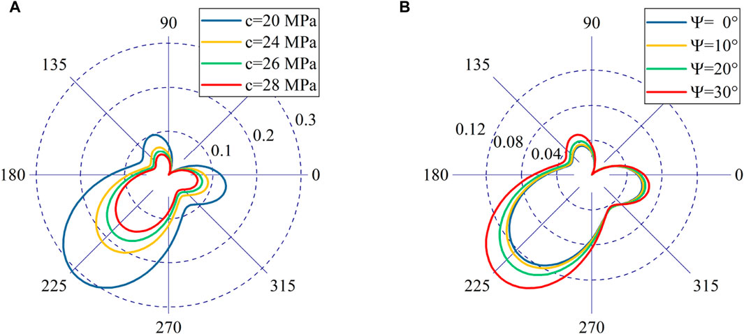
Figure 15. Influence of rock properties on the plastic zone. (A)
The shape of the plastic zone is similar for different angles of cohesion and internal friction, further confirming that the angle of crack propagation is independent of material properties. As the cohesive force increases, the yield strength of the material improves and the plastic zone decreases. However, Figures 15A, B shows that the plastic zone actually increases as the internal friction angle increases, which is clearly contrary to the expected pattern. The reason for this phenomenon is that the effect of lower order terms is neglected. Therefore, in high-precision analysis, the low-order terms cannot be neglected. Furthermore, as the internal friction angle increases, the rock’s brittleness gradually intensifies, leading to a more pronounced tensile failure effect. Consequently, the plastic zone radius in the direction of tensile stress at the crack tip progressively expands. In comparison to the influence of cohesion force on the plastic zone radius, the impact of internal friction angle is relatively minor. Therefore, in practical engineering applications, enhancing particle bonding and increasing material cohesion can effectively address crack propagation issues and significantly reduce the plastic zone radius at the crack tip.
To investigate the stress field distribution at the tip of a closed crack and the failure mode of rock under biaxial load, we derive calculation methods for the stress field and displacement field at the closed crack tip based on the superposition principle. Analysis of the stress field distribution reveals that tension-shear coupling plays a crucial role in wing crack formation. A smaller inclination angle and higher confining pressure effectively prevent surface sliding, reduce tension-shear coupling, and inhibit wing crack initiation. The internal friction angle and cohesion force do not alter crack propagation direction as they have no impact on plastic zone shape. Furthermore, when maintaining a certain crack angle, there are stress invariants and displacement invariants at the crack tip that are solely influenced by vertical load. This study presents a theoretical framework for conducting failure mode analysis of geotechnical materials.
The original contributions presented in the study are included in the article/Supplementary material, further inquiries can be directed to the corresponding author.
GW: Writing–review and editing. WW: Writing–review and editing, Funding acquisition. SP: Writing–original draft, Methodology.
The author(s) declare that financial support was received for the research, authorship, and/or publication of this article. This research is financially supported by the Natural Science Foundation of Sichuan Province (Grant No. 2022NSFSC1071), China Railway guiding project, China Railway Research Institute major special projects (Grant Nos 2020-KJ001-Z001-A1 and 2020-YD-302), Chengdu University of Technology 2023 Young and Middle-aged Backbone Teachers Development Funding Program (Grant No. 10912-SJGG2023-09012).
Author GW was employed by Northwest Research Institute Co., Ltd. of China Railway Engineering Corporation.
The remaining authors declare that the research was conducted in the absence of any commercial or financial relationships that could be construed as a potential conflict of interest.
All claims expressed in this article are solely those of the authors and do not necessarily represent those of their affiliated organizations, or those of the publisher, the editors and the reviewers. Any product that may be evaluated in this article, or claim that may be made by its manufacturer, is not guaranteed or endorsed by the publisher.
Ban, H., and Yao, Y. (2023). The coupling effects of strain gradient and damage on Mode I crack tip stress fields. Theor. Appl. Fract. Mech. 126, 103989. doi:10.1016/j.tafmec.2023.103989
Bi, J., Ning, L., Zhao, Y., Wu, Z., and Wang, C. (2023). Analysis of the microscopic evolution of rock damage based on real-time nuclear magnetic resonance. Rock Mech. Rock Eng. 56, 3399–3411. doi:10.1007/s00603-023-03238-x
Chen, F., Cao, P., Rao, Q., and Sun, Z. q. (2003). Use of double edge-cracked Brazilian disk geometry for compression-shear fracture investigation of rock. J. Central South Univ. Technol. 10 (3), 211–215. doi:10.1007/s11771-003-0011-0
Dolbow, J., Moës, N., and Belytschko, T. (2001). An extended finite element method for modeling crack growth with frictional contact. Comput. methods Appl. Mech. Eng. 190 (51-52), 6825–6846. doi:10.1016/s0045-7825(01)00260-2
Elguedj, T., Gravouil, A., and Combescure, A. (2007). A mixed augmented Lagrangian-extended finite element method for modelling elastic–plastic fatigue crack growth with unilateral contact. Int. J. Numer. Methods Eng. 71 (13), 1569–1597. doi:10.1002/nme.2002
Erdogan, F., Gupta, G. D., and Ratwani, M. (1974). Interaction between a circular inclusion and an arbitrarily oriented crack. J. Appl. Mech. 41 (4), 1007–1013. doi:10.1115/1.3423424
Hasebe, N., Wang, X., and Kondo, M. (2003). Interaction between crack and arbitrarily shaped hole with stress and displacement boundaries. Int. J. Fract. 119, 83–102. doi:10.1023/a:1023979717528
Hu, K. X., Chandra, A., and Huang, Y. (1993). Multiple void-crack interaction. Int. J. solids Struct. 30 (11), 1473–1489. doi:10.1016/0020-7683(93)90072-f
Huang, X. (2023). Roles of in-plane and out-of-plane T-stresses in crack tip plastic zones and fracture toughness under mixed mode I/II loading. Eng. Fract. Mech. 277, 108990. doi:10.1016/j.engfracmech.2022.108990
Isida, M. (1966). Crack tip stress intensity factors for a crack approaching a hole centered on its plane. Lehigh Univ.
Isida, M. (1970). On the determination of stress intensity factors for some common structural problems. Eng. Fract. Mech. 2 (1), 61–79. doi:10.1016/0013-7944(70)90030-5
Jiang, R., Dai, F., Liu, Y., and Feng, P. (2021). Frequency characteristics of acoustic emissions induced by crack propagation in rock tensile fracture. Rock Mech. Rock Eng. 54, 2053–2065. doi:10.1007/s00603-020-02351-5
Jing, P., Khraishi, T., and Gorbatikh, L. (2003). Closed-form solutions for the mode II crack tip plastic zone shape. Int. J. Fract. 122, L137–L142. doi:10.1023/b:frac.0000005806.28267.f6
Ju, M., Li, X., Li, X., and Zhang, G. (2022). A review of the effects of weak interfaces on crack propagation in rock: from phenomenon to mechanism. Eng. Fract. Mech. 263, 108297. doi:10.1016/j.engfracmech.2022.108297
Khoei, A. R., and Nikbakht, M. (2007). An enriched finite element algorithm for numerical computation of contact friction problems. Int. J. Mech. Sci. 49 (2), 183–199. doi:10.1016/j.ijmecsci.2006.08.014
Liu, W., Ma, L., Sun, H., and Muhammad Khan, N. (2021). An experimental study on infrared radiation and acoustic emission characteristics during crack evolution process of loading rock. Infrared Phys. Technol. 118, 103864. doi:10.1016/j.infrared.2021.103864
Ma, W., Chen, Y., Yi, W., and Guo, S. (2022). Investigation on crack evolution behaviors and mechanism on rock-like specimen with two circular-holes under compression. Theor. Appl. Fract. Mech. 118, 103222. doi:10.1016/j.tafmec.2021.103222
Ming, Z. Z., Sao Cheng, J., and He-Ping, X. (1996). An improved method of collocation for the problem of crack surface subjected to uniform load. Eng. Fract. Mech. 54 (5), 731–741. doi:10.1016/0013-7944(95)00187-5
Pan, J., Cai, M., Li, P., and Guo, Q. f. (2022). A damage constitutive model of rock-like materials containing a single crack under the action of chemical corrosion and uniaxial compression. J. Central South Univ. 29 (2), 486–498. doi:10.1007/s11771-022-4949-1
Peng, S., Jing, L., Li, S., Wu, D., and Jing, W. (2022). Analytical solution of the stress intensity factors of multiple closed collinear cracks. J. Vib. Eng. Technol. 11, 3737–3745. doi:10.1007/s42417-022-00779-3
Renji, T., and Yinbang, W. (1986). On the problem of crack system with an elliptic hole. Acta Mech. Sin. 2, 47–57. doi:10.1007/bf02487881
Sharafisafa, M., Aliabadian, Z., Tahmasebinia, F., and Shen, L. (2021). A comparative study on the crack development in rock-like specimens containing unfilled and filled flaws. Eng. Fract. Mech. 241, 107405. doi:10.1016/j.engfracmech.2020.107405
Sousa, R. A., Castro, J. T. P., Lopes, A. A. O., and Martha, L. F. (2013). On improved crack tip plastic zone estimates based on T-stress and on complete stress fields. Fatigue & Fract. Eng. Mater. Struct. 36 (1), 25–38. doi:10.1111/j.1460-2695.2012.01684.x
Wang, Y., Deng, H., Deng, Y., Chen, K., and He, J. (2021a). Study on crack dynamic evolution and damage-fracture mechanism of rock with pre-existing cracks based on acoustic emission location. J. Petroleum Sci. Eng. 201, 108420. doi:10.1016/j.petrol.2021.108420
Wang, Y. B., and Chau, K. T. (1997). A new boundary element for plane elastic problems involving cracks and holes. Int. J. Fract. 87, 1–20. doi:10.1023/a:1007469816603
Wang, Z., Li, Y., Cai, W., Zhu, W., Kong, W., Dai, F., et al. (2021b). Crack propagation process and acoustic emission characteristics of rock-like specimens with double parallel flaws under uniaxial compression. Theor. Appl. Fract. Mech. 114, 102983. doi:10.1016/j.tafmec.2021.102983
Wu, C., Gong, F., and Luo, Y. (2021). A new quantitative method to identify the crack damage stress of rock using AE detection parameters. Bull. Eng. Geol. Environ. 80, 519–531. doi:10.1007/s10064-020-01932-6
Xiao, W., Zhang, D., Yang, H., Li, X., Ye, M., and Li, S. (2021). Laboratory investigation of the temperature influence on the mechanical properties and fracture crack distribution of rock under uniaxial compression test. Bull. Eng. Geol. Environ. 80, 1585–1598. doi:10.1007/s10064-020-01993-7
Xin, G., Hangong, W., Xingwu, K., and Liangzhou, J. (2010). Analytic solutions to crack tip plastic zone under various loading conditions. Eur. J. Mechanics-A/Solids 29 (4), 738–745. doi:10.1016/j.euromechsol.2010.03.003
Yan, X., and Miao, C. (2012). A numerical method for a void–crack interaction under cyclic loads. Acta Mech. 223 (5), 1015–1029. doi:10.1007/s00707-011-0596-6
Yang, H., Lin, H., Wang, Y., Cao, R., Li, J., and Zhao, Y. (2021). Investigation of the correlation between crack propagation process and the peak strength for the specimen containing a single pre-existing flaw made of rock-like material. Archives Civ. Mech. Eng. 21, 68–21. doi:10.1007/s43452-021-00175-w
Yi, W., Rao, Q., Luo, S., Shen, Q. q., and Li, Z. (2020). A new integral equation method for calculating interacting stress intensity factor of multiple crack-hole problem. Theor. Appl. Fract. Mech. 107, 102535. doi:10.1016/j.tafmec.2020.102535
Zhang, S., Li, Y., Liu, H., and Ma, X. (2021). Experimental investigation of crack propagation behavior and failure characteristics of cement infilled rock. Constr. Build. Mater. 268, 121735. doi:10.1016/j.conbuildmat.2020.121735
Zhou, X. P., Zhang, J. Z., Yang, S. Q., and Berto, F. (2021). Compression-induced crack initiation and growth in flawed rocks: a review. Fatigue & Fract. Eng. Mater. Struct. 44 (7), 1681–1707. doi:10.1111/ffe.13477
Keywords: closed crack, stress field, displacement field, plastic zone, crack extension
Citation: Wu G, Wang W and Peng S (2024) Analytical solution of the stress field and plastic zone at the tip of a closed crack. Front. Earth Sci. 12:1370672. doi: 10.3389/feart.2024.1370672
Received: 15 January 2024; Accepted: 05 March 2024;
Published: 20 March 2024.
Edited by:
Bin Gong, Brunel University London, United KingdomReviewed by:
Ming Lan, University of South China, ChinaCopyright © 2024 Wu, Wang and Peng. This is an open-access article distributed under the terms of the Creative Commons Attribution License (CC BY). The use, distribution or reproduction in other forums is permitted, provided the original author(s) and the copyright owner(s) are credited and that the original publication in this journal is cited, in accordance with accepted academic practice. No use, distribution or reproduction is permitted which does not comply with these terms.
*Correspondence: Wensong Wang, d3dzQGNkdXQuZWR1LmNu
Disclaimer: All claims expressed in this article are solely those of the authors and do not necessarily represent those of their affiliated organizations, or those of the publisher, the editors and the reviewers. Any product that may be evaluated in this article or claim that may be made by its manufacturer is not guaranteed or endorsed by the publisher.
Research integrity at Frontiers
Learn more about the work of our research integrity team to safeguard the quality of each article we publish.