 Tao Wang1
 Liyuan Liu
 Weiwei Ye
95% of researchers rate our articles as excellent or good
Learn more about the work of our research integrity team to safeguard the quality of each article we publish.
Find out more
ORIGINAL RESEARCH article
Front. Earth Sci. , 27 February 2024
Sec. Geohazards and Georisks
Volume 12 - 2024 | https://doi.org/10.3389/feart.2024.1367933
This article is part of the Research Topic Risk Assessment, Stability Monitoring, and Safe Design for Deep Rock Engineering View all 20 articles
Extremely thick and hard roofs are difficult to break in the mining of a working face, and the large area of the suspended roof easily induces a strong ground pressure or dynamic impact disasters. The roof control of a coal mining face in a mine in western China was taken as a case study. The mineral composition, microstructure, and hydrophysical properties of the hard roof overlying the coal seam were analyzed. The characteristics of the weak-cementation strata that are prone to mud and collapse when encountering water were targeted to investigate the hydraulic softening roof-cutting and pressure relief technology. It was found that the clay mineral composition in the roof plate accounts for 60.6%. After 24 h of natural immersion, the rock strength decreased by approximately 10.3%–49%, and further immersion caused disintegration. By arranging high and low double-row water injection softening drilling holes in the cutting hole and roadway of the working face, the strength of roof rock strata in the target area was reduced, and the initial weighting step distance and weighting strength of the working face were reduced. The hydraulic softening roof-cutting pressure relief technology effectively regulated the weighting step distance of the hard roof and the peak weighting of the working face.
The large-scale exploitation of coal resources in western China has resulted in certain phenomena such as a strong rock pressure and dynamic damage (Mirenkov, 2020; Yang et al., 2021). A major factor affecting the working face weighting and dynamic impact disasters is the properties of the overlying roof rock above the coal seam (Alehossein and Poulsen, 2010). The giant thick roof plate tends to accumulate energy, and its rupture process and subsidence can increase the pressure on the working face, which would damage the supporting structure within the coal–rock mass. In severe cases, the accumulated energy may result in the uncontrollable deformation of the surrounding rock or cause impact dynamic disasters such as the crushing of the supporting structure or a coal outburst (He et al., 2012; Rozenbaum and Demekhin, 2014; Liu et al., 2023). Large hanging roof areas are easily formed in the hard roof during mining, and the roof failure often releases a significant amount of elastic energy, thereby triggering impact dynamic disasters (Pavlova et al., 2019; Xu et al., 2021). Therefore, relevant techniques are crucial for the prediction and prevention of dynamic impact disasters to ensure deep coal mining safety (Gu et al., 2022; Liu et al., 2023; Wang et al., 2023).
In the coal mining practice in western China, it is difficult to understand the rock pressure characteristics of several working faces in newly commissioned mines or in the initial mining stages of the mining areas (panel areas). The difficulty is due to the relatively hard and intact overburden structure. The structural hardness is manifested through the excessive weighting step of the initial pressure and the weighting timing unpredictability (Lian et al., 2023), resulting in a high rock pressure on the working face (Daniliev et al., 2022). These uncertainties pose certain risks to the mine production. Therefore, the control of hard-roof plate weighting has been extensively investigated, leading to the development of many practical solution technologies. For instance, deep hole blasting can be used to reduce the weighting step (Wang et al., 2013; Chen et al., 2022; Kan et al., 2022) or hydraulic fracturing of the roof (Moghadasi et al., 2019; Zheng et al., 2021; Liu, 2022). Similarly, slotting in the middle of the roof can prevent the roof from falling suddenly while supporting cutting, and mined-out areas or areas with a detached roof can be filled to eliminate the dynamic pressure impact caused by roof collapses (Chang et al., 2021; Sun et al., 2021). Additionally, mining protective layers can be installed to reduce the roof pressure (Zhang et al., 2020; Cheng et al., 2021; Lei et al., 2022), among other methods.
The geological formations in western China are mainly composed of Jurassic and Cretaceous strata. These formations have relatively recent diagenetic ages and certain special properties, such as weak cementation, easy weathering, and ease of becoming muddy and sandy when in contact with water. Consequently, mining operations in these formations face significant challenges (Liu et al., 2020; Liu et al., 2021; Liu et al., 2022; Asif et al., 2022; Liu et al., 2022; Li et al., 2022; Liu et al., 2023). This difficulty necessitates in-depth research on utilizing the geological characteristics of western China to implement targeted measures for preserving the weak-roof rock layer and regulating the working face weighting (Xu et al., 2018; Wang et al., 2023a; Wang et al., 2023b; Wang et al., 2023c). This study investigated the physical, mechanical, and hydrophysical properties of weakly cemented strata, using a coal mining face in a mine located in western China as a case study. The principles and implementation plans of the hydraulic softening for roof cutting and pressure relief techniques were examined, providing a reference for preventing and controlling high rock pressure and impact dynamic disasters according to local conditions in western China.
The coal mine is located in the western region of China and extracts coal from the Jurassic coal seam. The mining face is adjacent to the mined-out area on the west side and is bordered by solid coal on the east side. Figure 1 shows that the length of the mining face is 250 m, and it extends to a total distance of 2,603 m.
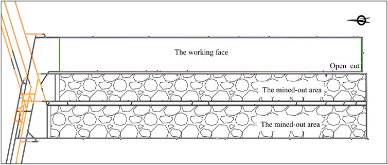
FIGURE 1. Layout of working face.
The mining face for the coal three to one seam is located in a stable coal layer. The thickness of the coal seam in the working face ranges from 1.1 m to 6.9 m. The coal seam is buried at an embedding depth of 527.6–571.7 m, with an average coal thickness of 5.18 m and a dip angle of 1–3°. During the initial mining and first release period, the mining height should be controlled at 5.5 m. The immediate roof of the coal seam consists of Jurassic sandy mudstone with a thickness of 2.6–22.0 m, which averages 12.5 m. The basic top comprises medium-to-fine sandstone, with a thickness of 4.2–16.3 m, averaging 10.3 m. The geological columnar diagram of the working face is shown in Figure 2.
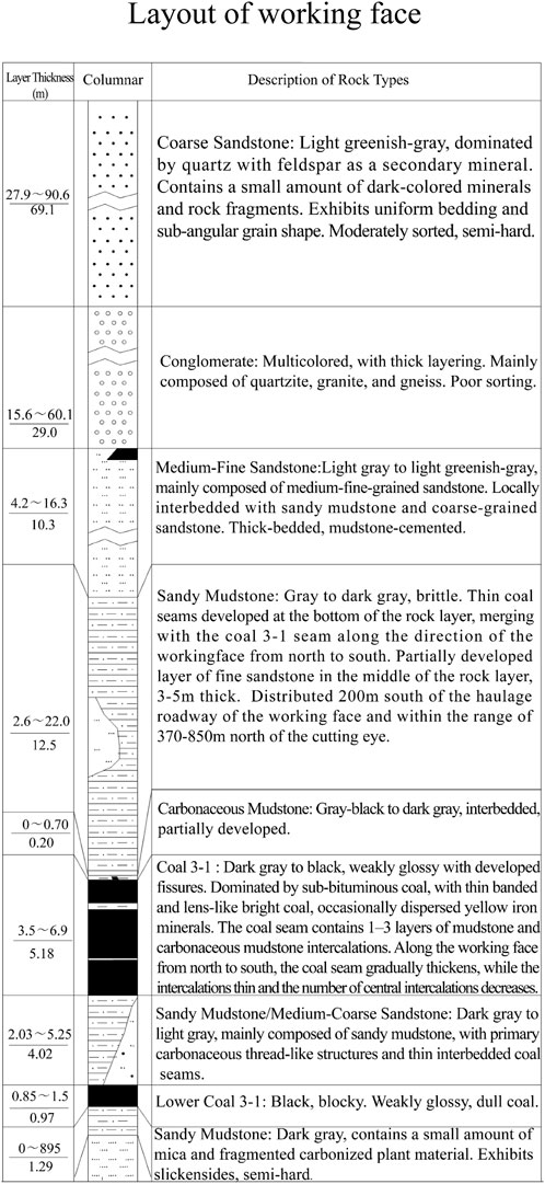
FIGURE 2. Geological borehole histogram.
Based on the geological borehole histogram, rock samples of the relevant layers of the coal seam roof were obtained using core drilling and processed in the laboratory to create standard specimens. Thirty-six standard specimens were prepared, representing three lithologies: the coal three to one, sandy mudstone of the immediate roof, and medium-to-fine sandstone of the basic top. Owing to the influence of the rock strata structure, more sandstone samples were obtained during the sample preparation.
The impact of the roof plate on the working face risk under natural conditions was investigated through pressure tests conducted on the specimens using a pressure testing machine. The tests provided the physical and mechanical parameters of the roof plate in their natural state, yielding an average uniaxial compressive strength of approximately 5.27 MPa for the coal samples. The average uniaxial compressive strength of the medium-to-fine sandstone and sandy mudstone samples was approximately 65.65 and 66.75 MPa, respectively. The specimens had a uniform compressive strength distribution, and the test results are shown in Table 1. The roof plate in their natural state exhibited a high strength and thickness, which had a significant impact on the pressure exerted on the working face.
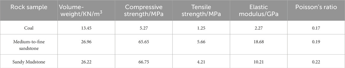
TABLE 1. Physical and mechanical parameters of the different rocks.
To explore methods for weakening the strength of the roof plate, an assay analysis was conducted on the roof plate rock, considering the weak cementation properties of the Jurassic formations. The results revealed that the main constituents of the rock were quartz, feldspar, and clay minerals, with clay minerals accounting for 60.6% of the composition. Notably, the content of high-expansive montmorillonite within the clay minerals peaked at 82%. This value indicates that the rock formation belongs to extremely swelling soft rock, which tends to react and expand when in contact with water.
To analyze the internal material distribution and structural morphology of the rocks, microscopic observations of the rock samples were performed using a scanning electron microscope (SEM). The SEM images of the sandy mudstone and medium-to-fine sandstone are shown in Figures 3, 4, respectively. Microscopically, both rock types exhibit a fragmented particle distribution. The shaly sand shows well-developed internal microfissures and noticeable linear fractures. The cementitious material in the medium-to-fine sandstone appears as flocculent aggregates, and the internal pores are well developed. The microscopic features indicate that the rocks possess a loose structure, making them prone to breaking into fragments or dispersoids when exposed to external factors and subjected to damage. Additionally, the pore structure exhibits good water absorption and permeability, leading to a high degree of softening and extensive fracturing of the rocks under the influence of water.
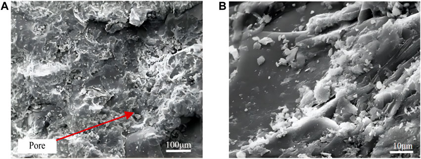
FIGURE 3. Microscopic characterization of sandy mudstone: (A) 500 times; (B) 1,000 times.
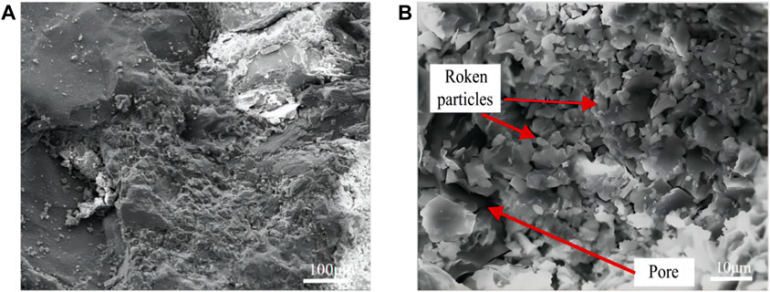
FIGURE 4. Microscopic characteristics of medium-to-fine sandstone: (A) 500 times; (B) 1,000 times.
The effects of the water-immersion softening of roof rocks and the mechanism of rock disintegration under prolonged water immersion conditions were studied through soaking experiments conducted on the sandy mudstone and medium-to-fine sandstone of the roof plate. The variations in the uniaxial compressive strength of the rock samples under different water content conditions were analyzed to assess the softening effect of water immersion. Additionally, the failure patterns of the rocks after long-term water immersion were observed to summarize the mechanism of water-soaking disintegration.
Laboratory experiments were conducted to compare the strength of the samples after water immersion. The water content of the rocks was artificially controlled, and Figure 5 illustrates the uniaxial compressive strength of the samples for different water contents. The results showed that after 24 h of natural water immersion, the water content of the sandy mudstone reached 3%, reducing the strength by approximately 10.3%–49%. For the medium-to-fine sandstone, the water content reached 2.4% after 24 h of water immersion, reducing the strength by approximately 26%. The softening effect of the sandstone under water immersion was more pronounced, with a significant increase in water absorption rate and a large decrease in strength.
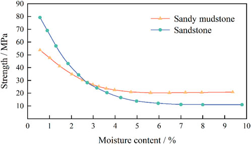
FIGURE 5. Different rocks’ strength versus water content.
Weakly cemented rock contains a higher content of cohesive clay minerals, which easily react with water. Subsequent experiments demonstrated that after the rocks reached water saturation under prolonged water immersion, their softening continued over time at a stabilized water absorption rate, and the strength continued to decrease.
Long-term immersion experiments were conducted on the specimens to observe the state of the rocks during water immersion. Figure 6 shows images comparing the states of the medium sandstone during immersion. At the initial immersion stage, the rock samples exhibited significant water absorption accompanied by bubble generation. Partially soluble matters on the rock surface were lost, and cracks were formed, gradually developing into fissures. Subsequently, the water–rock interaction proceeded slowly, causing the cementitious materials to dissolve and the rock particles to disintegrate gradually. Eventually, the sandstone became muddy overall.
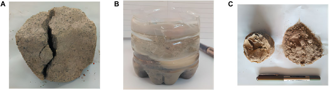
FIGURE 6. Hydrophysical characteristics of sandstone during different immersion times: (A) Pre-laboratory; (B) Soak for 3 days; (C) Soak for 28 days.
Figure 7 shows images of the sandy mudstone states during immersion. The disintegration damage of the sandy mudstone differed from that of the medium sandstone. During immersion, the sandy mudstone disintegration progressed more slowly, primarily undergoing water absorption and rock swelling. Subsequently, joints or microcracks expand and form cracks. The clay minerals within the rock are distributed in a band-like pattern that intersects in multiple directions. The ultimate failure of the rock is characterized by the formation of fragmented blocks accompanied by debris, as well as an overall fragmented disintegration.
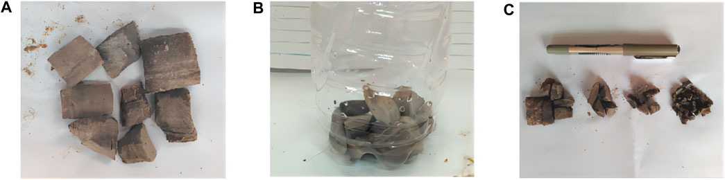
FIGURE 7. Hydrophysical characteristics of sandy mudstone during different immersion times: (A) Pre-laboratory; (B) Soak for 5 h; (C) Soak for 30 days.
The above experiments indicate that the water stability of weakly cemented rocks under these geological conditions can be classified into two categories. In the first category, the cementitious material of the rocks dissolves upon contact with water, causing the rock particles to disintegrate into fragments. An example of this category is the Jurassic medium sandstone. In the second category, the dense-lithology rocks possess well-developed joints and internal fractures. When exposed to water, these rocks undergo water absorption and swelling, causing the cracks to expand and propagate. Eventually, the rocks disintegrate into fragments. An example of this category is the Jurassic sandy mudstone.
The softening effect of water on rocks is mainly attributed to adsorption and absorption, hydration, wedging, and dissolution.
The rock disintegration described above is a failure phenomenon that occurs under continuous softening. This process can be summarized as the generation of secondary surface pores, pore connectivity leading to crack formation, generation of internal secondary pores, and internal fissure fragmentation through connectivity.
According to the softening process effects, the generation of secondary surface pores in rocks can be attributed to the following reasons, and the results are shown in Figure 8:
(1) Some minerals are water-soluble or can chemically react with water, forming secondary pores in their original positions.
(2) The dissolution of carbonate cement in rocks weakens the interconnection between rock particles, resulting in the loss of cementitious material and the formation of secondary pores.
(3) Clay minerals absorb water and swell, and the water molecules enter the crystal lattice of the clay minerals, causing secondary pores to expand and form along the stratification plane.
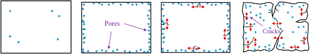
FIGURE 8. Disintegration process of rocks in contact with water.
An analysis of the hydrophysical properties of the roof plate shows that the rock exhibits good softening effects when exposed to water, and prolonged water immersion conditions cause disintegration. In engineering rock formations, this phenomenon is manifested as crack and joint expansion. These manifestations can enlarge the softened zone and enhance the softening effect, indicating that the roof plate possesses hydrophysical conditions necessary for inducing water injection softening.
According to geological exploration data and mining exposure data, the area within a range of 50–55 m above the coal three to one seam contains sequential layers of sandy mudstone (8.3 m), coarse sandstone (7.5 m), gravel layer (26–28 m), coarse sandstone (1.8 m), and fine-grained sandstone (7.4 m). A thick layer of coarse sandstone with a thickness ranging from 154 to 165 m exists above the 55 m mark. The rock pressure of the completed mining face indicates that the initial weighting step of the old roof is relatively large during the initial mining stage when influenced by the hard roof plate above the coal seam. The initial weighting step ranges from 31.6 to 47.8 m, and the support resistance weighting is between 36.8 and 42.0 MPa, as presented in Table 2. Excessive initial weighting steps hinder roof management in the working face and pose significant safety hazards to production operations.
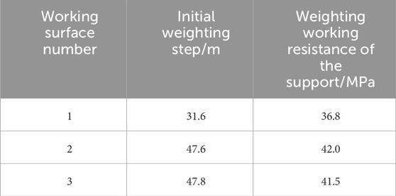
TABLE 2. Statistics of incoming weighting in the initial mining phase of the working face.
Owing to the slow cracking process, as well as the reversal and sinking of the massive sandstone layer with a total thickness exceeding 150 m above the coal three to one seam, the roof plate of the two adjacent mined-out areas become interconnected after the working face mining, forming a unified subsidence zone. During the mining process, the roof of the goaf, which is formed after three adjacent working faces are mined, may experience a phenomenon known as dynamic pressure. Therefore, it is necessary to regulate the roof plate weighting in the initial mining stage of this working face to effectively reduce the weighting step and control the weighting intensity. An excessive initial weighting step of the working face results in unfavorable conditions for the roof, posing significant safety hazards to the mining.
Because the Jurassic strata is prone to softening and disintegration when it encounters water, the initial weighting step of the immediate roof and the old roof can be significantly reduced by pre-softening the roof plate of the working face using an underground high-pressure water supply. This approach provides sufficient time for the cracking, reversal, and sinking of the massive sandstone layer above the working face while reducing the volume of subsided blocks in the massive sandstone layer. As a result, the instantaneous dynamic effects on the roof of the working face are minimized, ensuring the safe mining of the working face.
According to the columnar display of boreholes, the roof plate gravel layer in the local area belonging to the cut hole is approximately 40 m away from the roof plate of the coal three to one, with a thickness exceeding 150 m of the water-bearing sandstone layer above the gravel layer. Scientific exploration data show that the upper boundary of the gravel layer is generally consistent with the boundary of the water-conducting fracture zone. Softening and cutting the roof plate of the gravel layer and the underlying rock strata are crucial for controlling the rock pressure on the roof of the working face, as well as the degree of instantaneous dynamic manifestation of the massive sandstone layer. Considering the roof plate structure, the following water injection softening scheme is implemented:
(1) Cutting eye: Weakening treatments are conducted on the roof within a forward horizontal distance of 30 m and an upward distance of 48 m from the cutting eye. The treatments are conducted using 12 low-position boreholes and 15 high-position boreholes. The design of the high- and low-position boreholes ensures the coverage of the immediate roof, basic top, and hard rock overlying layers.
(2) Track side groove (on the mined-out area side): The roof of the track side groove is influenced by the adjacent mined-out area, and most of the area has been fractured. No water-injection softening boreholes are constructed in the track side groove.
(3) Belt side groove (on the solid coal side): For the roof of the belt side groove, seven boreholes are arranged at intervals of 7 m to soften the roof within a vertical distance of 45 m and a horizontal distance of 12 m above the coal seam.
The drilling parameters are presented in Table 3 and visually depicted in Figure 9 as follows:
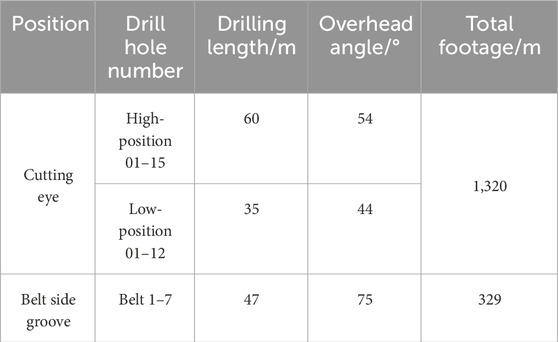
TABLE 3. Hydraulic softening top-cutting pressure relief borehole design.
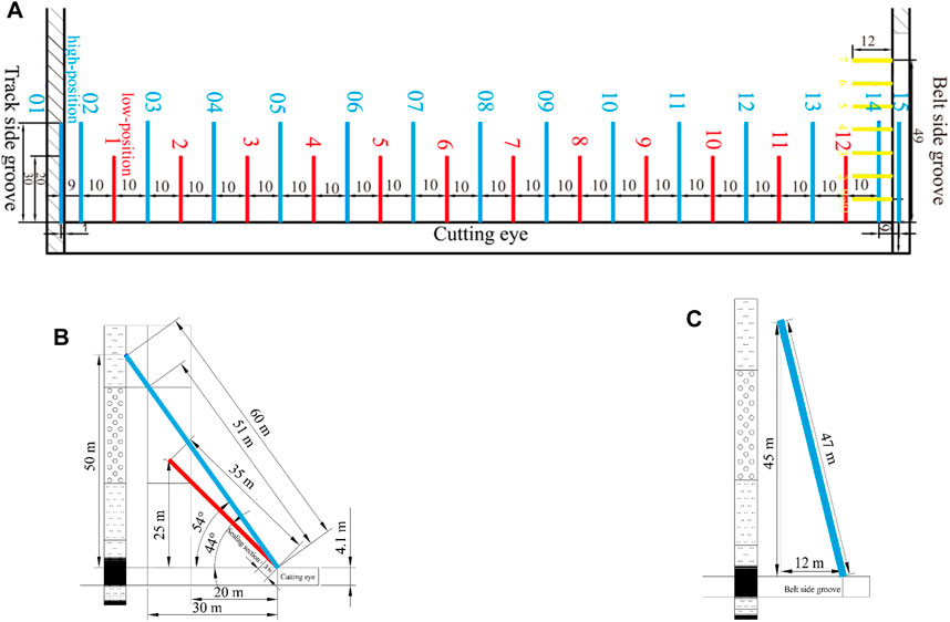
FIGURE 9. Arrangement of water-injection softening and pressure relief drill holes: (A) Borehole layout plan; (B) Cutting eye drilling profile; (C) Belt side drilling profile.
After completing the borehole construction, the AB glue sealing technique is used to seal the borehole. The sealing length is 3 m, and after sealing, a valve is installed at the borehole opening. Subsequently, a high-pressure water pump is connected to maintain an injection water pressure of 5.0 MPa, ensuring that the borehole is filled with water and exerts a certain outward diffusion pressure. The determination of the appropriate water injection volume directly affects the water injection effect. The water injection operation lasts for 10 days.
To investigate the effect of hydraulic softening roof cutting and pressure relief, a numerical simulation of the evolution of the stress field after roof cutting in the working face was performed using Flac3D software. The Mohr–Coulomb elastoplastic model was used for the constitutive behavior. The model dimensions were established according to the actual dimensions of the original structure, with a size of 800 m × 837 m × 270 m. Displacement constraints were applied to the bottom and lateral boundaries, and a load of 8.75 MPa was applied to the top to simulate the overburden pressure. The structural positions in the model are illustrated in Figure 10.

FIGURE 10. Numerical model working face: (A) 3D model; (B) Drill hole distribution.
In the working face, water injection boreholes are arranged in the cutting eye and tape side groove to soften the roof plate by injecting water inward. Long-term pressurized water injection can enhance the softening effect on the coal-rock mass, weakening the strength of the strata within a 40 m range above the coal seam and promoting the expansion of borehole cracks, which is beneficial for roof pressure management. Figure 11 shows the distribution of the stress field in the water injection area. It can be observed that the rock mass strength is reduced in the central region of the water injection borehole, and the bearing stress is transferred to the deeper part of the rock mass. The vertical stress values decrease simultaneously, with some areas reducing by up to 3.5 MPa, indicating the presence of stress concentration regions in the roof above the boreholes. As the working face advances, the stress concentration regions further expand, and the hard roof plate fractures.
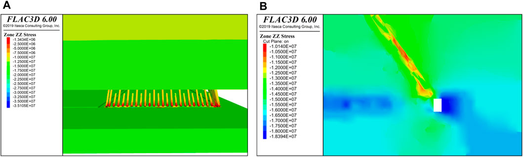
FIGURE 11. Stress field distribution in the water-injection softening area of the working face: (A) Zone of influence of vertical stress on the oblique profile of the injection borehole; (B) Zone of influence of vertical stress in the vertical profile of the injection borehole.
By analyzing the evolution of the stress field and plastic zone during the mining process after arranging the water-injection softening boreholes, we can assess the effectiveness of hydraulic softening in fracturing the roof plate and avoiding large-scale roof hanging, thereby controlling rock pressure accumulation.
To analyze the influence of hydraulic softening boreholes on the stress field of surrounding coal–rock mass, the vertical stress evolution was analyzed along the direction of the hydraulic softening boreholes, with the cutting eye coal wall being the origin. The vertical stress around the boreholes remained high at a mining depth of 10 m. At this stage, the roof could still transmit the pressure from the upper part of the mined-out area to the coal wall after the cutting eye, and the softening effect had not yet manifested. When mining reached a depth of 20 m, the low-stress regions around the boreholes spread and connected with one other, forming stress reduction zones in the lower rock layers along the borehole profile. Hence, the stress transfer of the immediate roof and part of the basic top were cut off. At a mining depth of 30 m, the stress reduction zone expanded to the entire height of the boreholes. The strength of the rock layers around the borehole profile decreased, and the roof transitioned to a state of support into two sides. The results are shown in Figure 12.
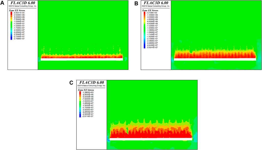
FIGURE 12. Vertical stress evolution in oblique profile of working face cut-hole drilling: (A) Recovery 10 m; (B) Recovery 20 m; (C) Recovery 30 m.
After the excavation of the working face, the stress in the coal seam is transmitted to the surrounding areas. To analyze the stress state in the roof region, the stress field evolution profile was analyzed, using the mid-section of the working face as the origin. As the working face is excavated, a pressure arch is formed, and the stress is concentrated in front of the coal wall and behind the mined-out area, forming stress arch feet. As the working face advances, the concentration of stress on the arch feet increases. At a mining depth of 30 m, the stress arch foot in front of the coal wall reaches 23 MPa, and the results are shown in Figure 13. The hydraulic softening weakens the strength of the roof, and the roof pressure is transmitted to the sides. The supporting pressure in front of the coal wall increases, fracturing the roof in the high-stress area in front of the coal wall and collapsing the roof above the mined-out area along the borehole profile.
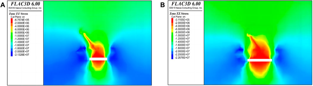
FIGURE 13. Vertical stress evolution in the middle section of the working face: (A) Recovery 20 m; (B) Recovery 30 m.
At a mining depth of 30 m, the mined-out area expands, and the hanging area of the roof increases. The mining field stress causes cracks to propagate in the roof plate. After hydraulic softening, the plastic zone in the roof plate extends and exhibits a destructive distribution at a depth of 10 m above the roof, indicating the occurrence of fracture. At a mining depth of 20 m, the plastic zone in the roof plate expands, but it becomes evident at a depth of 40 m. This indicates that the roof of the working face undergoes fracture at approximately 30 m of mining depth. The results are shown in Figure 14.
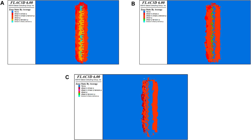
FIGURE 14. Evolution of the plastic zone of the roof plate 30 m back in the working face: (A) 10 m above the roof plate; (B) 20 m above the roof plate; (C) 40 m above the roof plate.
After implementing the hydraulic softening roof-cutting program as described above, the stress of the supports in the working face was analyzed during the initial mining phase to examine the rock pressure characteristics. The statistics analyses were performed for eight consecutive days. The distribution curve of support resistance in Figure 15 shows that as the footage increases, high-support resistance occurs in the middle and lower parts of the working face. On the sixth day, when the coal mining machine advanced to 22.4 m, the initial weighting occurred in the upper roof. The stress generated when the initial weighting occurs is shown in Figure 16. The maximum support pressure was 43.85 MPa (130# support), the minimum was 18.9 MPa (25# support), and the average was 31.9 MPa.
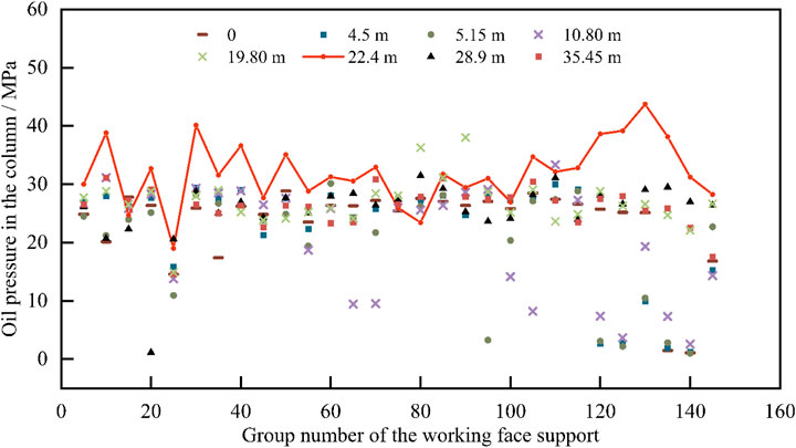
FIGURE 15. Distribution curve of brace resistance in the working face at the initial mining stage.
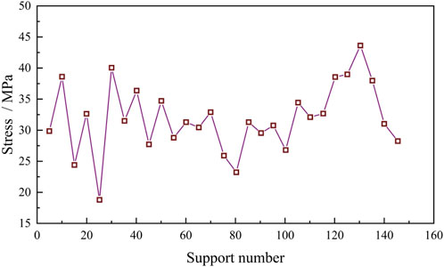
FIGURE 16. Bracket stress curve at the initial pressure of the basic top.
With the initial weighting of the basic top, the coal strength near the coal wall reaches its ultimate failure strength, generating abnormal noises and causing extensive spalling of the piece. These phenomena can be utilized to forecast the initial weightage of a working face in influencing an index. The high stress in the coal gradually transfers toward the front of the coal wall. Then, the roof in the mined-out area collapses, revealing large blocks of white sandstone gangue. During the initial weighting of the working face, a large amount of water is not encountered in the roof, indicating that the water injection and softening zone in the roof is controllable, and there is no leakage of water injection.
(1) The clay mineral composition in the roof plate accounts for 60.6%, causing the loose internal structure of the rock and easy softening and disintegration when water is encountered. After natural water immersion for 24 h, the strength decreases by approximately 10.3%–49%.
(2) Weak-cementation strata are prone to disintegration when encountered with water. The action of water leads to the formation of secondary pores in the rock, which then connect to form cracks. These cracks continue to expand and generate new pores until the intact rock is fragmented. This indicates the hydraulic conditions required for implementing water injection softening measures in the roof.
(3) By arranging high and low double-row water-injection softening boreholes in the cutting eye and roadway of the working face, the strength of the roof plate in the target area is reduced. The initial weighting step of the working face is 22.4 m, with a maximum support pressure of 43.85 MPa. The hydraulic softening and top-cutting unloading technique effectively controls the hard roof weighting step and the peak weighting value in the working face.
The original contributions presented in the study are included in the article/Supplementary material, further inquiries can be directed to the corresponding author.
TW: Conceptualization, Supervision, Validation, Formal Analysis, Methodology, Project administration, Resources, Writing–original draft. GX: Conceptualization, Formal Analysis, Methodology, Validation, Writing–original draft, Data curation, Software. LL: Conceptualization, Software,Validation, Funding acquisition, Supervision, Writing–review and editing. CB: Methodology, Software, Supervision, Validation, Writing–review and editing. WY: Investigation, Methodology, Project administration, Supervision, Validation, Writing–review and editing. LS: Conceptualization, Data curation, Investigation, Project administration, Supervision, Writing–review and editing.
The author(s) declare financial support was received for the research, authorship, and/or publication of this article. This work was funded by National Natural Science Foundation of China (Grant Nos. 52004015, 51874014, and 52311530070), the fellowship of China National Postdoctoral Program for Innovative Talents (Grant No. BX2021033), the fellowship of China Postdoctoral Science Foundation (Grant Nos. 2021M700389 and 2023T0025), and the Fundamental Research Funds for the Central Universities of China (Grant No. FRF-IDRY-20-003).
These supports are gratefully acknowledged.
The authors declare that the research was conducted in the absence of any commercial or financial relationships that could be construed as a potential conflict of interest.
All claims expressed in this article are solely those of the authors and do not necessarily represent those of their affiliated organizations, or those of the publisher, the editors and the reviewers. Any product that may be evaluated in this article, or claim that may be made by its manufacturer, is not guaranteed or endorsed by the publisher.
Alehossein, H., and Poulsen, B. A. (2010). Stress analysis of longwall top coal caving. Int. J. Rock Mech. Min. Sci. 47, 30–41. doi:10.1016/j.ijrmms.2009.07.004
Asif, M., Wang, L., Wang, R., Wang, H., and Hazlett, R. D. (2022). Mechanisms in CO2-enhanced coalbed methane recovery process. Adv. Geo-Energy Resour. 6, 531–534. doi:10.46690/ager.2022.06.09
Chang, Q., Sun, Y., Leng, Q., Liu, Z., Zhou, H., and Sun, Y. (2021). Stability analysis of paste filling roof by cut and fill mining. Sustainability 13, 10899. doi:10.3390/su131910899
Chen, B., Liu, C., and Wang, B. (2022). A case study of the periodic fracture control of a thick-hard roof based on deep-hole pre-splitting blasting. Energy explor. Exploit. 40, 279–301. doi:10.1177/01445987211036245
Cheng, X., Zhao, G., Li, Y., Meng, X., Tu, Q., Huang, S., et al. (2021). Mining-Induced pressure-relief mechanism of coal-rock mass for different protective layer mining modes. Adv. Mater. Sci. Eng. 2021, 1–15. doi:10.1155/2021/3598541
Daniliev, S., Danilieva, N., Mulev, S., and Frid, V. (2022). Integration of seismic refraction and fracture-induced electromagnetic radiation methods to assess the stability of the roof in mine-workings. Miner 12, 609. doi:10.3390/min12050609
Gu, B., Wang, L., and Zhang, M. (2022). Assessment of risk tendency of coal bursting pressure in deep outburst seam. Geofluids 2022, 1–9. doi:10.1155/2022/9150738
He, J., Dou, L., Cao, A., Gong, S., and Lü, J. (2012). Rock burst induced by roof breakage and its prevention. J. Cent. South Univ. 19, 1086–1091. doi:10.1007/s11771-012-1113-3
Kan, J., Dou, L., Li, X., Li, J., and Chai, Y. (2022). Investigating the destressing mechanism of roof deep-hole blasting for mitigating rock bursts in underground coal mines. Geomatics Nat. Hazards Risk. 13, 2508–2534. doi:10.1080/19475705.2022.2122594
Lei, W., Chai, J., Zhang, Y., Ding, G., Yao, R., Chen, Y., et al. (2022). Study on pressure relief effect of upper protective coal seam mining based on distributed optical fiber sensing monitoring. Opt. Fiber Technol. 68, 102830. doi:10.1016/J.YOFTE.2022.102830
Li, H., Jiang, X., Xu, Z., and Bowden, S. (2022). The effect of supercritical CO2 on failure mechanisms of hot dry rock. Adv. Geo-Energy Resour. 6, 324–333. doi:10.46690/ager.2022.04.07
Lian, X., Li, C., Li, J., and Wu, L. (2023). Law of strata pressure behavior of surrounding rock in nearby goaf roadway for extra-thick coal seams of Datong mine area. Front. Earth Sci. 2023, 10. doi:10.3389/FEART.2022.1015378
Liu, H., Feng, X., Liu, L., Li, T., and Tang, C. (2023a). Mechanical properties and failure characteristics of anisotropic shale with circular hole under combined dynamic and static loading. Int. J. Rock Mech. Min. Sci. 170, 105524. doi:10.1016/j.ijrmms.2023.105524
Liu, L., Ji, H., Elsworth, D., Zhi, S., Lv, X., and Wang, T. (2020). Dual-damage constitutive model to define thermal damage in rock. Int. J. Rock Mech. Min. Sci. 126, 104185. doi:10.1016/j.ijrmms.2019.104185
Liu, L., Ji, H., Lu, X., Wang, T., Zhi, S., Pei, F., et al. (2021). Mitigation of greenhouse gases released from mining activities: a review. Int. J. Min. Metall. Mater. 28, 513–521. doi:10.1007/s12613-020-2155-4
Liu, L., Zhang, Z., Wang, T., Zhi, S., and Wang, J. (2022a). Evolution characteristics of fracture volume and acoustic emission entropy of monzogranite under cyclic loading. Geomech. Geophys. Geo-Energy Geo-Resour. 10, 16. doi:10.1007/s40948-024-00737-1
Liu, W., Du, W., Guo, Y., and Li, D. (2022b). Lithology prediction method of coal-bearing reservoir based on stochastic seismic inversion and Bayesian classification: a case study on Ordos Basin. J. Geophys. Eng. 19, 494–510. doi:10.1093/jge/gxac033
Liu, W. J., Yang, K., He, X., Zhang, Z., and Xu, R. (2023b). Mechanism and control technology of rockburst induced by thick hard roof and residual coal pillar: a case study. Geofluids 2023, 1–16. doi:10.1155/2023/3523592
Liu, X., Zhang, S., Wang, E., Zhang, Z., Wang, Y., and Yang, S. (2023c). Multi-index geophysical monitoring and early warning for rockburst in coalmine: a case study. Int. J. Environ. Res. Public Health. 20, 392. doi:10.3390/ijerph20010392
Liu, Y. (2022). Investigation on pressure relief and roadway protection technology by subsection hydraulic fracturing under strong mining pressure in fully mechanized mining. Geofluids 2022, 1–11. doi:10.1155/2022/9151766
Mirenkov, V. E. (2020). Influence of stresses and displacements in roof rocks on roof fracture in top coal caving. J. Min. Sci. 56, 203–208. doi:10.1134/s1062739120026650
Moghadasi, R., Rostami, A., and Hemmati-Sarapardeh, A. (2019). Application of nanofluids for treating fines migration during hydraulic fracturing: experimental study and mechanistic understanding. Adv. Geo-Energy Resour. 3, 198–206. doi:10.26804/ager.2019.02.09
Pavlova, L. D., Fryanov, V. N., Keller, A. V., and Tsvetkov, A. B. (2019). Numerical study of the effect of console length of the main roof hanging on the geomechanical parameters of the mine face. IOP Conf. Ser. Earth Environ. Sci. 377, 012037. doi:10.1088/1755-1315/377/1/012037
Rozenbaum, M. A., and Demekhin, D. N. (2014). Deformational criteria for the stability of roof rocks and rock bolts. J. Min. Sci. 50, 260–264. doi:10.1134/s1062739114020082
Sun, Q., Zhou, N., Song, W., and Xu, Z. (2021). Risk assessment and prevention of surface subsidence under buildings by cemented paste filling and strip mining methods: a case study. Adv. Civ. Eng. 2021, 1–10. doi:10.1155/2021/9965279
Wang, C., Si, G., Zhang, C., Cao, A., and Canbulat, I. (2023). Variation of seismicity using reinforced seismic data for coal burst risk assessment in underground mines. Int. J. Rock Mech. Min. Sci. 165, 105363. doi:10.1016/j.ijrmms.2023.105363
Wang, F., Tu, S., Yuan, Y., Feng, Y., Chen, F., and Tu, H. (2013). Deep-hole pre-split blasting mechanism and its application for controlled roof caving in shallow depth seams. Int. J. Rock Mech. Min. Sci. 64, 112–121. doi:10.1016/j.ijrmms.2013.08.026
Wang, T., Liu, Z., Liu, L., and Feng, X. (2023a). Numerical study on the impact of locked-in stress on rock failure processes and energy evolutions. Materials 16, 7519. doi:10.3390/ma16247519
Wang, T., Ye, W., Liu, L., Li, A., Jiang, N., Zhang, L., et al. (2023b). Impact of Crack.Inclination angle on the splitting failure and energy analysis of fine-grained sandstone. Appl. Sci. 13, 7834. doi:10.3390/app13137834
Wang, T., Ye, W., Tong, Y., Jiang, N., and Liu, L. (2023c). Residual stress measurement and analysis of siliceous slate-containing quartz veins. Int. J. Min. Metall. Mater. 30, 2310–2320. doi:10.1007/s12613-023-2667-9
Xu, G., Yu, J., Fan, Z., Xue, Ji., Liu, Q., Li, Z., et al. (2021). Characteristics of strata pressure behavior of working face under typical roof conditions in China. J. China Coal Soc. 46, 25–37. doi:10.13225/j.cnki.jccs.2020.1678
Xu, Q., Shi, W., Xie, X., Busbey, A. B., Xu, L., Wu, R., et al. (2018). Inversion and propagation of the late paleozoic porjianghaizi fault (north ordos basin, China): controls on sedimentation and gas accumulations. Mar. Pet. Geol. 91, 706–722. doi:10.1016/j.marpetgeo.2018.02.003
Yang, D., Ning, Z., Li, Y., Lv, Z., and Qiao, Y. (2021). In situ stress measurement and analysis of the stress accumulation levels in coal mines in the northern Ordos Basin. China. Int. J. Coal Sci. Technol. 8, 1316–1335. doi:10.1007/s40789-021-00407-7
Zhang, X., Hu, J., Xue, H., Mao, W., Gao, Y., Yang, J., et al. (2020). Innovative approach based on roof cutting by energy-gathering blasting for protecting roadways in coal mines. Tunn. Undergr. Space Technol. 99, 103387. doi:10.1016/j.tust.2020.103387
Keywords: weakly consolidated formation, giant thick roof plate, hydraulic softening, pressure relief technique, roof-cutting
Citation: Wang T, Xu G, Liu L, Bai C, Ye W and Sun L (2024) Principle and practice of hydraulic softening top-cutting and pressure relief technology in weakly cemented strata. Front. Earth Sci. 12:1367933. doi: 10.3389/feart.2024.1367933
Received: 09 January 2024; Accepted: 15 February 2024;
Published: 27 February 2024.
Edited by:
Bin Gong, Brunel University London, United KingdomReviewed by:
Jun Liu, Sichuan University, ChinaCopyright © 2024 Wang, Xu, Liu, Bai, Ye and Sun. This is an open-access article distributed under the terms of the Creative Commons Attribution License (CC BY). The use, distribution or reproduction in other forums is permitted, provided the original author(s) and the copyright owner(s) are credited and that the original publication in this journal is cited, in accordance with accepted academic practice. No use, distribution or reproduction is permitted which does not comply with these terms.
*Correspondence: Liyuan Liu, bGl1bGl5dWFuQHVzdGIuZWR1LmNu
Disclaimer: All claims expressed in this article are solely those of the authors and do not necessarily represent those of their affiliated organizations, or those of the publisher, the editors and the reviewers. Any product that may be evaluated in this article or claim that may be made by its manufacturer is not guaranteed or endorsed by the publisher.
Research integrity at Frontiers
Learn more about the work of our research integrity team to safeguard the quality of each article we publish.