 Dapeng Yang1,2
 Tiezheng Li
 Yang Li
 Yuqi Ren
95% of researchers rate our articles as excellent or good
Learn more about the work of our research integrity team to safeguard the quality of each article we publish.
Find out more
ORIGINAL RESEARCH article
Front. Earth Sci. , 09 May 2024
Sec. Economic Geology
Volume 12 - 2024 | https://doi.org/10.3389/feart.2024.1361749
Mining in an upper coal seam results in the redistribution of vertical stress within a lower coal seam until a new equilibrium state is attained. Close-multiple coal seams mining faces the occurrence of multi-goafs and a complex stress environment. Based on a case study of close-multiple coal seams with repeated mining in the Qianjiaying coal mine, a stress distribution model of the floor in the coal seam striking range was established by optimizing the load form of the abutment pressure. The floor stress state after primary and repeated mining of upper coal seams was analyzed in a visual and quantitative manner. The concentrations of vertical stress, horizontal stress, and shear stress are all located in the floor under the coal rib after primary and repeated mining. The curve of stresses gradually levels off as the depth of the floor increases, indicating a diminishing influence of mining-induced stress from the upper coal seam. Based on the stress analysis by numerical simulations, the overall lower coal seam remains in a state of large-scale stress relief. Stress relief occurred twice under repeated mining, which indicates that the lower coal seam has favorable mining feasibility. The results of the study can provide scientific guidance to prevent mining accidents.
Multiple minable coal seams are ubiquitous in major mining regions worldwide. The distances between coal seams vary significantly, ranging from just over 1 m to hundreds of meters. In the process of close coal seam mining, the structural integrity of the floor is destroyed, and the stress environment undergoes alterations when the upper coal seam is mined. When mining the lower coal seam, the risk of surrounding rock disasters such as roof falls, rib spalling, and pillar collapse is heightened due to the influence of upper coal seam mining (Qian and Xu, 2019; Arka et al., 2020; Li et al., 2022a). The smaller the coal seam spacing, the greater the influence of the repeated mining of the upper coal seam on the lower coal seam mining. Understanding the failure of the floor due to upper coal seam mining is pivotal in optimizing the safe and efficient mining of the lower coal seam (Sun et al., 2019; Liu et al., 2021; Chen and Liu, 2022; Liu et al., 2022).
Considerable research efforts have been dedicated to researching failure development and overburden movement. The collapsed roof of the secondary mining in the goaf was revealed, and roof structure movement under the slanting pillar-beam zone was divided into two stages to solve the problem of support load determination (Huang et al., 2018). A “loosen-blocky” roof structure model was constructed to analyze the stability of the roof structure, and the roof falling mechanism and dynamic process in the lower seam mining were revealed (Zhu et al., 2010a). Li et al. investigated the movement of roof structures under repeated mining and its impact on the stability of the end-face roof. The direct fracture and hinged structure fracture of the cantilever beam structure under repeated mining is a significant reason for the end face roof leaks and support failure (Li et al., 2022b). Lai et al. utilized the borehole TV system and the acoustic emission system for physical similarity simulation monitoring. Analysis revealed a phased relationship between the overlying strata fracture and fracture expansion under mining conditions while noting a high energy level in the collapse zone (Lai et al., 2021). High mine pressure and gas concentration are typically found in close seam group mining under thin immediate roofs. Gao et al. investigated the distribution of blasting stress and blasting cracks in hard rock by theoretical analyses, numerical simulations, and simulation experiments, which improved the effect of increasing the gas drainage rate of high-level boreholes (Gao et al., 2021).
The area below the gob is a stress-reducing area, and the area below a pillar is a stress-increasing area; hence, the roadway in the lower coal seam should be outside of the diffusion angle in order to avoid the influence of the stress-increasing area. The finite element technique and semi-analytical methods were combined to assess the stress state underneath supercritical longwall panels. The results show that the vertical stress distribution is primarily influenced by the abutment angle, overburden depth, pillar width, and the anisotropic behavior of the rock mass (Suchowerska et al., 2013). Overlying or underlying pillars behave as “pseudo gobs” that have the most unsafe stress concentration, and a variety of methods were summarized to mitigate hazards (Gauna and Mark, 2017). Yin et al. used in situ dynamic monitoring and revealed that the relationship between the maximum vertical stress increment and the depth of the floor is inverse exponential, whereas the relationship between the maximum horizontal stress increment and depth(Yin et al., 2016). Wang et al. revealed the dynamic evolution of cracks and distribution of abutment stress in roof strata under residual pillars using the Voronoi method and proposed some measures to ensure safety in longwall mining (Wang et al., 2019). Additional stress distribution of the floor strata was presented, and the stress intensity factors for the cracks at different positions were obtained to predict crack growths in confined aquifers in floor strata (Sun et al., 2018). Liu et al. established a floor stress-solving mechanics model of the oblique seam, and the maximum damage depth in the floor was obtained by theoretical calculations, numerical simulations, and a site experiment using a borehole leak detection device (Liu et al., 2017). With mining of the coal face, the overburden weight is transferred to both sides of the coal pillars, which causes the gangue to collapse into the gob. A process of separating, cracking, collapsing, and compacting will repeatedly occur in the roof, and the collapse interval of the roof is about 10–20 m (Ye et al., 2018).
In summary, in a mine with rich gas and rock outburst tendencies, the stress-relief zone in the floor plays a crucial role in preventing gas outbursts and rock outburst accidents. Meanwhile, the stress-increasing zone in the floor provides valuable guidance for the rational layout of entries and panel faces. The research established the stress distribution model of any point on the floor acting as an abutment pressure in the coal seam striking range by optimizing the load form of the abutment pressure. The mining feasibility of the lower coal seam under repeated mining was evaluated by analyzing the floor stress distribution law after the mining of the upper coal seam. The pressure relief area of the floor obtained by the study has a positive effect on the prevention of mining accidents.
In the mining of close-multiple coal seams, the stress distribution of the coal seam floor readjusts and reaches a new equilibrium state influenced by mining disturbances. Consequently, the stress within the floor undergoes a continuous dynamic adjustment process throughout the mining period until mining ends. Stress analysis of the floor is conducted in conjunction with the theory of an elastic semi-infinite plane (Zhu et al., 2007; Zhu et al., 2013). It is assumed that the goaf and the coal rock mass under coal are elastic materials. The vertical stresses are distributed along the upper boundary MN of a semi-infinite body, with a load concentration of q, as illustrated in Figure 1.
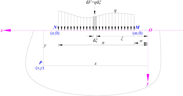
Figure 1. Semi-infinite plane boundary under distributed loading.
To determine the stress state at any point P within the semi-infinite body, a rectangular coordinate system was established with the horizontal leftward direction as the positive x-axis and the vertical downward direction as the positive y-axis. The coordinates of point P are (x, y), and a small length dξ was taken along the upper boundary MN at a distance ξ from the origin O. The force dF acting on it was considered as a tiny concentrated force. The stress state at point P due to this small concentrated force is expressed by Eq. 1:
Superimposing the stress caused by all the infinitesimal concentrated forces within the MN range results in Eq. 2.
During coal seam mining, the main roof forms stable voussoir beam structures by squeezing against each other. Assuming the fracture line of the main roof is located within the coal seam along the strike of the coal seam, the loading from the main roof and its overlying strata is transmitted downward through the coal seam to the coal floor. Simultaneously, the accumulated gangue within the goaf area reaches a residual stress state. This results in the stress distribution in the mining field, as illustrated in Figure 2.
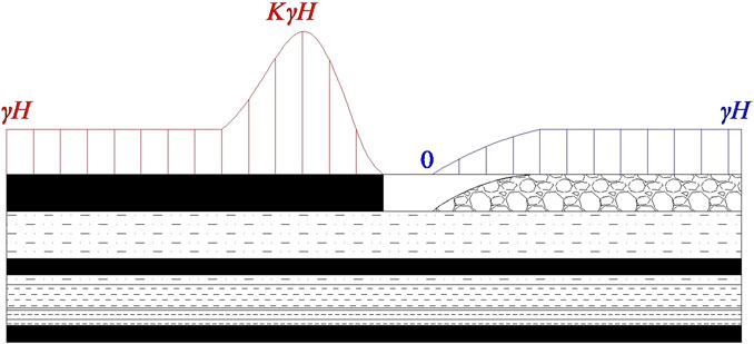
Figure 2. Abutment pressure distribution during coal seam mining.
Considering the relationship between the abutment pressure and the original rock stress, along with the characteristics of elastic-plastic deformation of the solid coal, the stress distribution was divided into six regions, namely, Zone a, Zone b, Zone c, Zone d, Zone e, and Zone f, as illustrated in Figure 3. Zone a represents the area where the abutment pressure on the coal rib is equal to the original rock stress, Zone b represents the area from the original rock stress to the peak abutment pressure on the coal rib, Zone c represents the area from the peak abutment pressure to zero abutment pressure on the coal rib, Zone d represents the area where abutment pressure of the panel face is zero, Zone e represents the area from zero abutment pressure to the original rock stress on the goaf, and Zone f represents the area where the abutment pressure on the goaf is equal to the original rock stress. K is the stress concentration factor in the coal wall in front of the working face during the coal mining process, and γH is the original rock stress when the coal seam is intact.
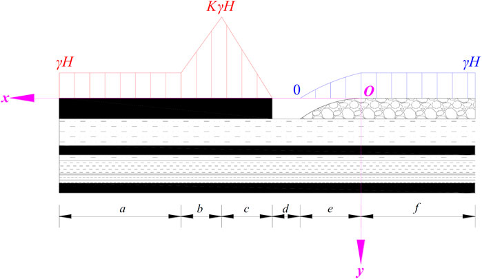
Figure 3. Abutment pressure distribution during coal seam mining (simplified).
The abutment pressures within Zones a, d, and f can be approximated as uniformly distributed loads, and the abutment pressures within Zones b and c can be approximated as linear loads. For Zone e, the goaf gangue will form a parabolic-shaped “discrete” arch after collapse, accumulation, and compaction under the influence of the overlying strata as weight, as illustrated in Figure 4 (Li et al., 2008).
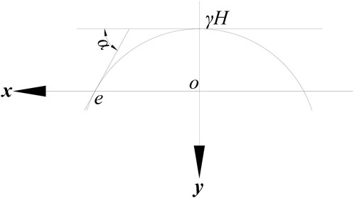
Figure 4. Simplified balanced structure of a discrete arch with a given load.
By simplifying the discrete arch structure, a parabolic equation can be assumed for the idealized structure, as shown in Eq. 3.
The parabola of the discrete arch passes through two points (0, −γH) and (e, 0), as shown in Figure 4, and, after calculating, the equation is shown as Eq. 4.
Without considering the influence of tectonic stress on the floor stress distribution, the abutment pressure of coal and goaf can be represented by Eq. 5.
By combining Equations 1 and (2), the stress components at any point P (x, y) of the floor of different zones during coal seam mining can be calculated as follows.
(1) Zone a:
(2) Zone b:
(3) Zone c:
(4) Zone d:
(5) Zone e:
(6) Zone f:
By applying the principle of stress superposition, the stress components at any point P (x, y) of the floor under the influence of abutment pressure are superimposed, as expressed in Eq. 12.
It is necessary to determine the widths of each region (a, b, c, d, e, and f) to obtain the vertical stress. The width b is calculated using Equation 13, and the width c is calculated using Equation 14 (Lu et al., 2008; Chen et al., 2010).
where m is the mining thickness of the coal seam, β is the lateral pressure coefficient, f0 is the friction factor between the coal seam and the contact surfaces of the floor and roof, K is the stress concentration factor, ζ0 is the triaxial stress coefficient, C0 is the cohesion of coal, and φ0 is the internal friction angle of coal.
The width d is approximately taken as the width of the setup entry.
The width e was calculated using Equation 15.
This study is based on the No. 7, No. 8, and No. 9 coal seams located in the Qianjiaying Mine in the Kailuan coalfield. The average thickness of each coal seam is 4.0 m, 1.4 m, and 1.9 m, respectively, and the average distance of two adjacent coal seams is about 5.3 m and 5.6 m. The coal-bearing strata in the Qianjiaying coal mine are shown in Figure 5. The mining sequence of the coal seams is No. 7, No. 8, and No. 9. Therefore, typical close-multiple coal seams are formed, characterized by small distances between each seam and significant variations in thickness and quality.

Figure 5. Column of rock mass and coal seam.
Combining the storage feature of the coal seams in the Kailuan Mining Area, the relevant parameters of a typical coring test of the roof and floor strata, coal mining conditions, and production technology and experience are shown in Table 1. With a model length of 200 m, as taken from Figure 3, where the widths of the solid coal and goaf are each 100 m, the floor stress state after mining of the upper coal seam was analyzed in a visual and quantitative manner using Mathcad software.
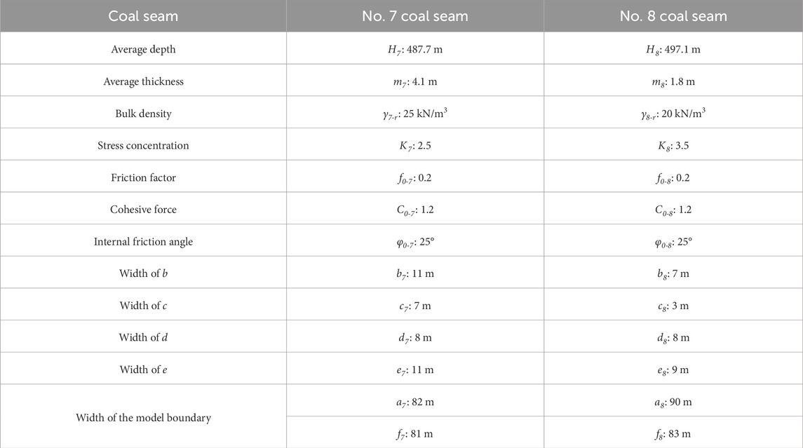
Table 1. Calculation parameters.
The floor stress distribution characteristics during mining of the upper coal seam along the strike of the coal seam can be obtained by bringing these parameters into equations 5–15, as shown in Figure 6.
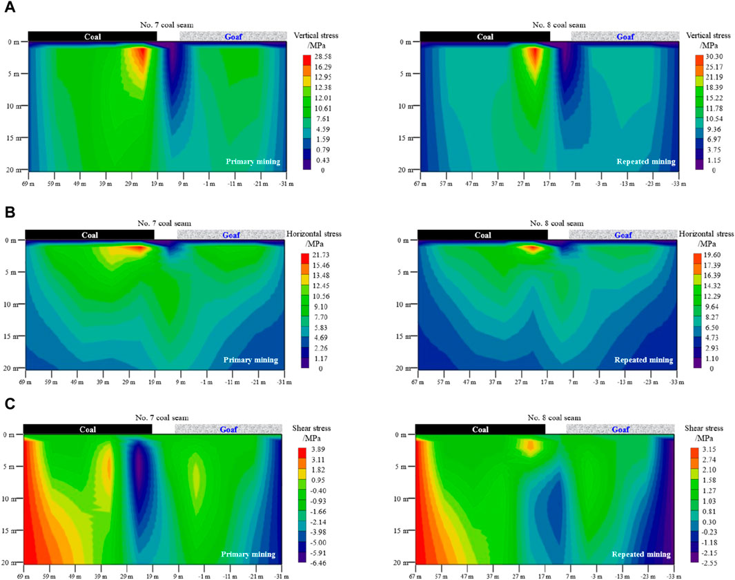
Figure 6. Floor stress distribution along strike during mining of the upper coal seams. (A) Vertical stress; (B) Horizontal stress; (C) Shear stress.
The increasing zone of abutment pressure in the panel face rib significantly affects floor stress under the influence of mining in the upper coal seam. The concentrations of vertical stress, horizontal stress, and shear stress are all situated within the floor under the coal rib after primary mining and repeated mining, in which the vertical stress concentration of the floor is greater than the horizontal stress. As shown in Figure 6C, the maximum shear stress occurs in the floor near the panel face rib under both single and repeated mining of the upper coal seam. The positive and negative shear stresses exhibit a “reverse spiral” distribution, which propagates obliquely downward at a certain angle with the panel face rib floor and the goaf floor, respectively. The distribution of abutment pressure under the panel face rib differs from the distribution under the goaf, leading to significantly greater negative shear stress than positive shear stress.
The vertical stress, horizontal stress, and shear stress at different depths in the floor (5 m, 10 m, 15 m, and 20 m) under the influence of abutment pressure induced by the mining of the upper coal seam are shown in Figure 7.
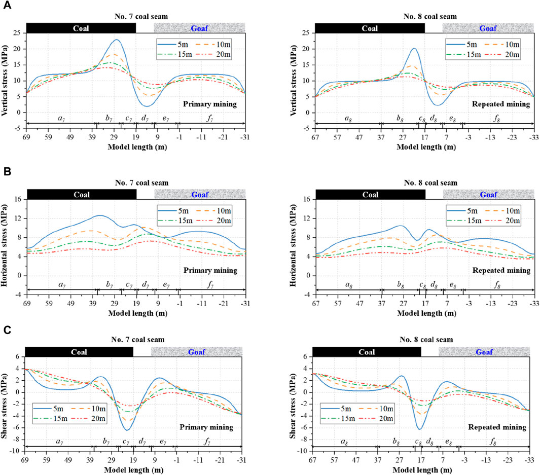
Figure 7. Floor stress distribution at different depths during mining of the upper coal seams. (A) Vertical stress; (B) Horizontal stress; (C) Shear stress.
As the depth of the floor increases, the curves of vertical stress, horizontal stress, and shear stress gradually level off, indicating a diminishing influence of mining-induced stress from the upper coal seam. Additionally, the following patterns are observed regarding the maximum (positive) and minimum (negative) stresses and their distribution at different depths of the bottom plate:
(1) It can be observed that in the panel face rib at depths of 5 m, 10 m, 15 m, and 20 m, the maximum vertical stresses are located in the floor, in the increasing zone of abutment pressure in the panel face rib (Figure 7A). On the other hand, the minimum vertical stresses are located within the floor of the panel face. In addition, Figure 8A shows that the difference between the maximum and minimum vertical stresses of the floor at different depths gradually decreases, which indicates that the disturbance degree caused by mining from the upper coal seam diminishes as the depth of the floor increases.
(2) As shown in Figure 7B, in the floor at a depth of 5 m near the panel face rib, the maximum horizontal stress is located in the floor of the increasing zone of abutment pressure in the panel face, rib, and the minimum horizontal stress is located in the floor of the decreasing zone of abutment pressure in the goaf. Meanwhile, the distributions of horizontal stress at depths of 10 m, 15 m, and 20 m are the opposite. This suggests that the horizontal stress in the shallow strata of the floor is primarily influenced by the front abutment pressure of the panel face. However, the original rock stress is released, and the influence of the front abutment pressure gradually diminishes in the deeper strata of the floor.
(3) As shown in Figure 7C, the negative shear stress is located in the floor of the decreasing zone of abutment pressure in the panel face rib. Meanwhile, the positive shear stress is symmetrically distributed about negative shear stress as the axis of symmetry, which is found in the floor of the increasing zone of abutment pressure in the panel face rib and the decreasing zone of abutment pressure in the goaf. Furthermore, Figures 8B,C also reveal that as the depth of the floor increases, the degree of disturbance caused by mining decreases.
Figure 8. Maximum (positive) and minimum (negative) stress difference of the floor. (A) Vertical stress; (B) Horizontal stress; (C) Shear stress.
In summary, because the No. 7 coal seam (primary mining) was mined before the No. 8 coal seam (repeated mining), the floor was affected by the unloading effect of the primary mining and then underwent unloading again after repeated mining. This led to a general decrease in stress levels in the floor after repeated mining compared to those after primary mining. However, the stress in the shallow strata of the floor is generally higher than that in the deeper strata of the floor near the panel face rib affected by the superimposed abutment pressure.
Based on the depth of the lower, No. 9, coal seam, the vertical, horizontal, and shear stresses in the lower coal seam are 12.61 MPa, 13.86 MPa, and 0 MPa, respectively, when the upper coal seams are not mined. With the panel face of the upper coal seam as the origin, the stress distribution characteristics of the lower coal seam within a range of 50 m in front and behind the panel face rib are as follows:
(1) The vertical stress in both lower coal seams changed due to the primary and repeated mining. As shown in Figure 9, the stresses can be divided into zones of increasing stress and decreasing stress along the strike of the coal seam. The range of the stress-increasing zone after primary mining extends approximately 24 m, whereas it is reduced to 10 m after repeated mining. The maximum vertical stress after primary mining and repeated mining is 16.29 MPa and 17.95 MPa, respectively, which indicates that pressure relief occurred twice in the floor, resulting in a reduced increase in the stress concentration factor. The maximum vertical stress of the lower coal seam is concentrated within the floor in the increasing zone of abutment pressure in the panel face rib.
(2) As shown in Figure 10, the horizontal stress in the entire lower coal seam decreases after mining of the upper coal seam and exhibits a “double peak” shape. One peak is located under the origin zone of abutment pressure in the coal rib of the upper coal seam, and the other peak is located under the panel face of the upper coal seam. The primary mining and repeated mining of the upper coal seams result in varying degrees of reduction of the horizontal stress in the lower coal seam. The repeated mining of the upper coal seam has a greater impact on the horizontal stress of the lower coal seam.
(3) As shown in Figure 11, the overall change in the shear stress of the lower coal seam exhibits a similar trend, forming a “V” shape that alternates between negative shear stress and positive shear stress. The bottom of the “V” shape is located in the panel face. The three endpoints of the “V” correspond to the positive peak shear stress, the negative peak shear stress, and the second positive peak shear stress. In addition, the primary mining and repeated mining of the upper coal seam result in a larger difference in the shear stress of the lower coal seam.
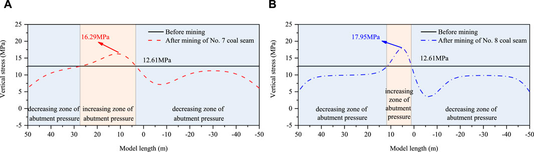
Figure 9. Vertical stress of the No. 9 coal seam after repeated mining. (A) After mining of No.7 coal seam; (B) After mining of No.8 coal seam.
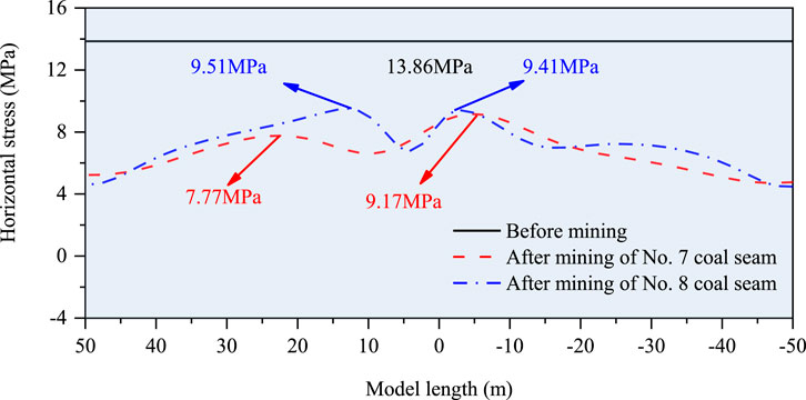
Figure 10. Horizontal stress of the No. 9 coal seam after repeated mining.
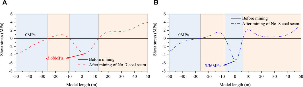
Figure 11. Shear stress of the No. 9 coal seam after repeated mining. (A) After mining of No.7 coal seam; (B) After mining of No.8 coal seam.
In order to further substantiate the aforementioned theoretical analyses, this section employs a numerical simulation approach using UDEC (Universal Distinct Element Code) software. This method facilitates a visual, quantitative investigation into the evolution of the stress field within the coal and rock layers of the underlying strata. This examination is carried out under the influence of repeated mining activities in the overlying coal seam, with the goal of better understanding the dynamic response of the strata.
According to the geological condition of the Qianjiaying Mine, a numerical model with 600 m length and 150 m height is established. The model uses the method of limited displacement and given load, in which the left and right boundaries of the model are horizontal displacement constraints, the bottom part is vertical displacement constraints, and a vertical load of 10.78 MPa is applied to the upper boundary of the model to simulate the actual load that has not been established. The Mohr–Coulomb model is used for the coal and rock mass, and the goaf is used by the full collapse method. The No. 7 coal seam and the No. 8 coal seam are mined successively, with a total of 300 m of advancement, and the distance of each advance is 20 m. The stress monitoring line is arranged in the No. 9 coal seam. Boundary coal pillars (150 m) are left on the left and right sides. The numerical modeling process is shown in Figure 12, and the numerical model is shown in Figure 13. The physical and mechanical parameters of the coal and strata layer from the bottom are shown in Table 2.
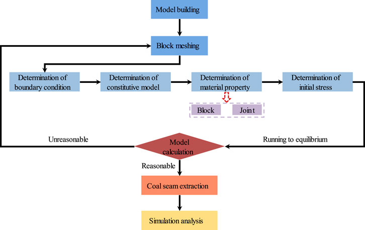
Figure 12. Flowchart of the numerical simulation process.
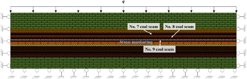
Figure 13. Numerical model.
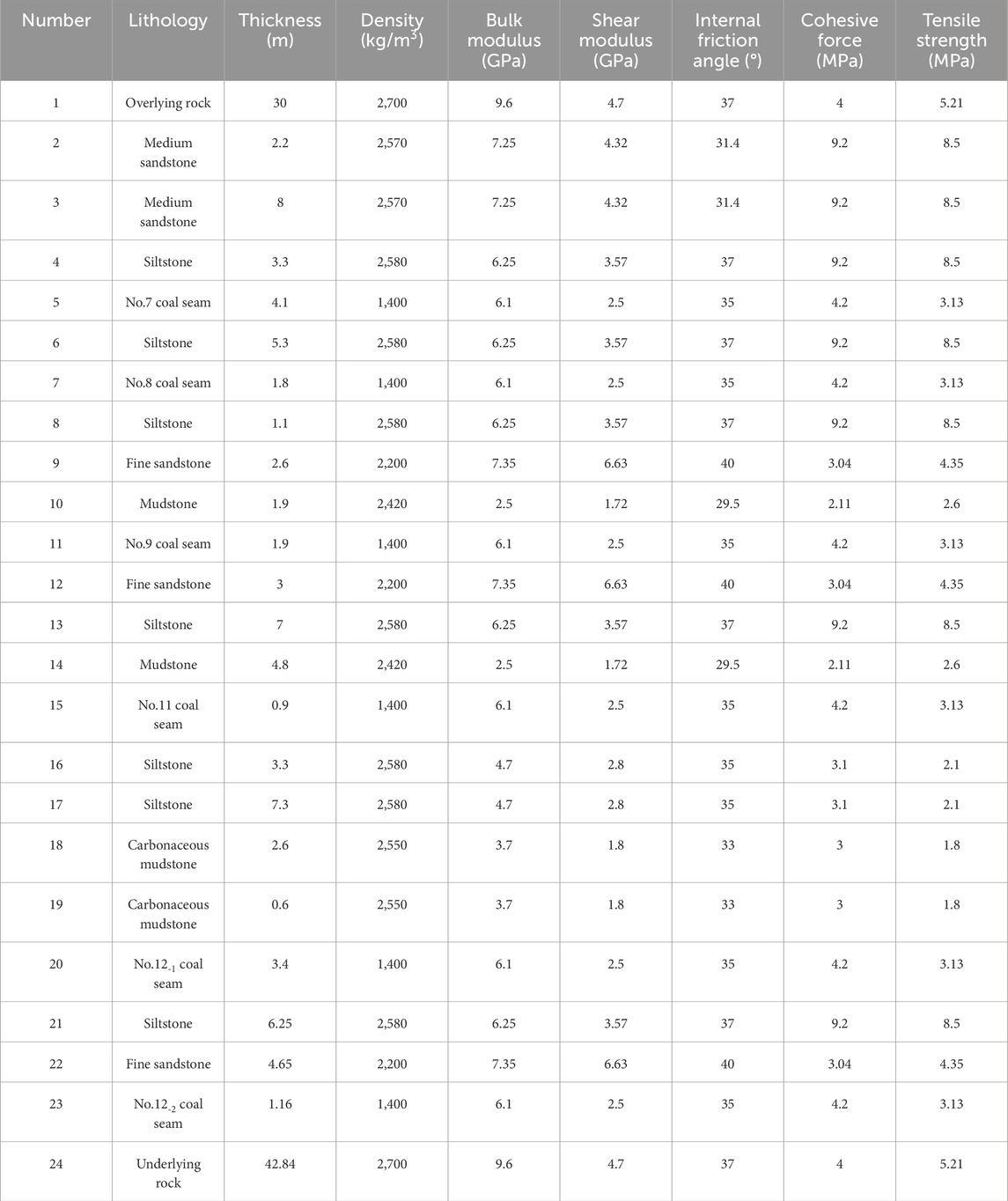
Table 2. Parameters of rock in the numerical model.
The rationality of the model is mainly judged according to the roof weighting during the coal seam mining, as shown in Figure 14. The measured cyclic weighting interval of the No. 7 coal seam is 15–20 m, and the interval of the No. 7 coal seam is 10–20 m. The model calculation is reasonable.
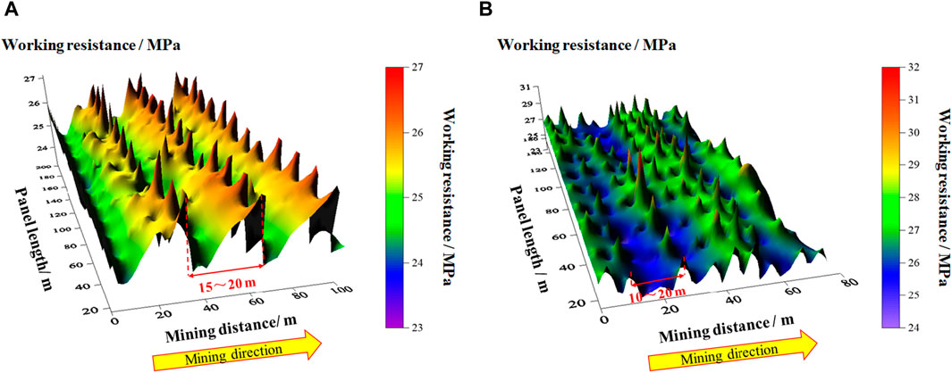
Figure 14. Field measurement results of roof weighting. (A) The No.7 coal seam; (B) The No.8 coal seam.
Figure 15 illustrates the vertical stress distribution characteristics of the surrounding rock during the mining of the No. 7 coal seam. There is a periodic variation of stress release–stress recovery–stress concentration in local areas of the No. 9 coal seam under the goaf. Due to the fracture, collapse, and compaction in the roof under the goaf, the stress in the roof transmits downward along the compacted areas, which results in localized stress concentration in the corresponding area of the No. 9 coal seam under the goaf after the completion of mining in the No. 7 coal seam. Nevertheless, the overall No. 9 coal seam remains in a state of large-scale stress relief.
Figure 15. Vertical stress distribution law during the No. 7 coal seam mining. (A) 0 m; (B) 40 m; (C) 100 m; (D) 160 m; (E) 220 m; (F) 280 m.
Figure 16 shows the vertical stress distribution characteristics of the surrounding rock during the mining of the No. 8 coal seam. The periodic variation of stress release–stress recovery–stress concentration in the No. 9 coal seam appears under the goaf. In contrast, the phenomena of stress superposition and stress concentration are observed in the No. 9 coal seam under the unmined areas of the No. 8 coal seam. In addition to the stress concentration caused by boundary pillars of the No. 8 coal seam, localized stress concentration also occurs in the central area of the goaf after mining in the No. 8 coal seam. Furthermore, stress relief occurred twice in the No. 9 coal seam under the influence of mining in both the No. 7 and No. 8 coal seams.
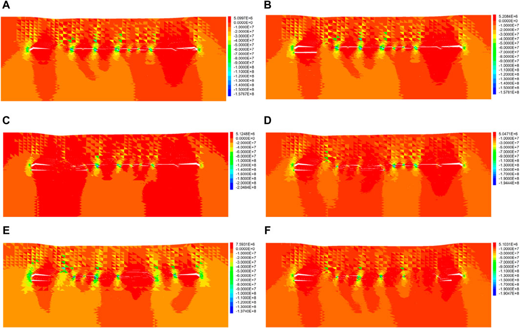
Figure 16. Vertical stress distribution law during the No. 8 coal seam mining. (A) 0 m; (B) 40 m; (C) 100 m; (D) 160 m; (E) 220 m; (F) 280 m.
Figure 17 illustrates the vertical stress distribution of the No. 9 coal seam under different mining distances of the No. 7 coal seam and the No. 8 coal seam. The vertical stress shows a trend of initial increase followed by stabilization as the No. 7 coal seam continues to advance. The distance between the peak of vertical stress in the No. 9 coal seam and the area corresponding to the coal rib of the No. 7 coal seam is generally 5 m, while the distance becomes 15 m when the No. 7 coal seam advances to 20 m and 120 m. This phenomenon can be attributed to the fact that the immediate roof did not experience initial fracture and collapse when the No. 7 coal seam was advanced to 20 m, forming a clamped beam structure. The stress of the roof transmits towards the No. 9 coal seam, and the distance decreases after the fracture and collapse of the immediate roof. When the No. 7 coal seam advances to 120 m, the main roof forms a hinge structure, supported on one end by the gangues in the goaf and on the other end by the coal side ahead. Additionally, the gangues in the goaf are compacted, resulting in the pressure transmitting from the roof towards the coal side of the No. 9 coal seam. Then, the distance starts to decrease following the fracture of the immediate and main roofs.
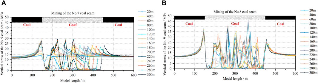
Figure 17. Vertical stress distribution law of the No. 9 coal seam mining. (A) Mining of the No.7 coal seam; (B) Mining of the No.8 coal seam.
The vertical stress under boundary pillars initially increases, followed by stabilization as the No. 8 coal seam continues to advance. In contrast, the vertical stress in areas under the goaf of the No. 8 coal seam exhibits a complex trend characterized by an initial increase, subsequent decrease, another increase, and, finally, a decrease. This is caused by the superimposition from the stress from the mining of the No. 8 coal seam and the roof stress transmitted by the compaction of the goaf gangue of the No. 7 coal seam.
This paper primarily investigates the stress response mechanism of the coal seam under mining in the upper seam of close-multiple coal seams using theoretical analysis and numerical simulations. The feasibility of downward mining in the No. 9 coal seam was determined. The following conclusions are drawn:
(1) The concentration of vertical stress, horizontal stress, and shear stress are all located in the floor under the coal rib after primary mining and repeated mining. The positive and negative shear stresses exhibit a “reverse spiral” distribution, which propagates obliquely downward at a certain angle with the panel face rib floor and the goaf floor, respectively. The distribution of abutment pressure under the panel face rib differs from the distribution under the goaf, leading to significantly greater negative shear stress than positive shear stress, with maximum positive stresses of approximately 3.89 MPa and 3.15 MPa and maximum negative stresses of approximately −6.46 MPa and −2.55 MPa, respectively.
(2) After the mining of the upper No. 7 and No. 8 coal seams, the vertical stress of the No. 9 coal seam can be divided into stress-increasing and stress-decreasing zones, while horizontal stress remains within a decreasing stress range. The shear stress is in a “V” shape that alternates between negative shear stress and positive shear stress. The mining of the No. 8 coal seam results in greater stress disturbance than the mining of the No. 7 coal seam. However, the stress reduction zone in the No. 9 coal seam expands.
(3) Based on numerical simulations, there is a periodic variation of stress release–stress recovery–stress concentration in the No. 9 coal seam under the goaf. Localized stress concentration areas in the No. 9 coal seam appear due to the recompaction of collapsed gangue, while stress relief occurred twice in the No. 9 coal seam under the influence of mining in both the No. 7 and No. 8 coal seams. The overall No. 9 coal seam remains in a state of large-scale stress relief that contributes to its mining.
The original contributions presented in the study are included in the article/Supplementary Material; further inquiries can be directed to the corresponding author.
DY: writing–original draft and writing–review and editing. TL: writing–original draft. YL: writing–review and editing. YR: writing–original draft.
The author(s) declare that financial support was received for the research, authorship, and/or publication of this article. This study was funded by the National Key Research and Development Program of China (Grant No. 2022YFC3004603), the Open Fund of State Key Laboratory of Coal Resources and Safe Mining (Grant No. SKLCRSM22KFA10), the National Natural Science Foundation of China (Grant No. 52074293), and the Natural Science Foundation of Hebei Province, China (Grant No. E2020402041).
The authors declare that the research was conducted in the absence of any commercial or financial relationships that could be construed as a potential conflict of interest.
All claims expressed in this article are solely those of the authors and do not necessarily represent those of their affiliated organizations, or those of the publisher, the editors, and the reviewers. Any product that may be evaluated in this article, or claim that may be made by its manufacturer, is not guaranteed or endorsed by the publisher.
Arka, J. D., Prabhat, K. M., Amar, P., L. Lal, B. R., and Subhashish, T. (2020). Underground extraction methodology of contiguous coal seams ensuring the safety of the parting and the surface structures. Saf. Sci. 121, 215–230. doi:10.1016/j.ssci.2019.09.010
Chen, K., Bai, J. B., Hu, Z. C., and Zhu, Q. (2010). Analysis of influence of advance abutment pressure on dip and rational end-mining line selection. Coal Min. Technol. 15 (1), 35–37. doi:10.13532/j.cnki.cn11-3677/td.2010.01.005
Chen, L., and Liu, Q. (2022). The research of the influence on stress below the roadway floor of the coal seam becoming thin. Geofluids 2022, 1–6. doi:10.1155/2022/4964740
Gao, K., Huang, P., Liu, Z. G., Liu, J., Wang, F., and Shu, C. M. (2021). Pressure relief by blasting roof cutting in close seam group mining under thick sandstone to enhance gas extraction for mining safety. Processes 9 (4), 603. doi:10.3390/pr9040603
Gauna, M., and Mark, C. (2017). Unanticipated multiple seam stresses from pillar systems behaving as pseudo gob–case histories. Int. J. Min. Sci. Technol. 27 (1), 131–137. doi:10.1016/j.ijmst.2016.11.015
Huang, Q. X., Cao, J., and He, Y. P. (2018). Analysis of roof structure and support load of mining face under ultra-close goaf in shallow multiple seams. Chin. J. Rock Mech. Eng. 37 (S1), 3153–3159. doi:10.13722/j.cnki.jrme.2016.1196
Lai, X. P., Liu, B. W., Shan, P. F., Cui, F., Zhang, Y., Zhang, X. D., et al. (2021). Study on the prediction of the height of two zones in the overlying strata under a strong shock. Geofluids 2021, 1–14. doi:10.1155/2021/4237061
Li, H. T., Liu, C. Y., and Wang, L. Q. (2008). Generating and destabilization evolutionary of granular arch structure of upper immediate roof. J. China coal Soc. 33 (4), 378–381. doi:10.13225/j.cnki.jccs.2008.04.008
Li, Q., Wu, G. Y., and Kong, D. Z. (2022a). Study on stability of stope surrounding rock under repeated mining in close-distance coal seams. Geofluids 2022, 1–17. doi:10.1155/2022/9630942
Li, Q., Wu, G. Y., Kong, D. Z., Han, S., and Ma, Z. Q. (2022b). Study on mechanism of end face roof leaks based on stope roof structure movement under repeated mining. Eng. Fail. Anal. 135, 106162. doi:10.1016/j.engfailanal.2022.106162
Liu, C., Zhang, P. S., Shang, J. X., Yao, D. X., Wu, R. X., Ou, Y. C., et al. (2022). Comprehensive research on the failure evolution of the floor in upper mining of deep and thick coal seam. J. Appl. Geophys. 206, 104774. doi:10.1016/j.jappgeo.2022.104774
Liu, H. T., Huo, T. H., Li, Y. G., Luo, M., Zhou, G. D., and He, Z. J. (2021). Numerical simulation study on the distribution law of deviatoric stress of floor under the influence of mining. Geofluids 2021, 1–14. doi:10.1155/2021/6666621
Liu, S. L., Liu, W. T., and Shen, J. J. (2017). Stress evolution law and failure characteristics of mining floor rock mass above confined water. KSCE J. Civ. Eng. 21 (7), 2665–2672. doi:10.1007/s12205-017-1578-6
Lu, Y., Fan, S. Q., and Zou, X. Z. (2008). Distributing law of advanced abutment pressure in working face. J. Liaoning Tech. Univ. Nat. Sci. 2, 184–187.
Qian, M., and Xu, J. L. (2019). Behaviors of strata movement in coal mining. J. China coal Soc. 44 (4), 973–984. doi:10.13225/j.cnki.jccs.2019.0337
Suchowerska, A. M., Merifield, R. S., and Carter, J. P. (2013). Vertical stress changes in multi-seam mining under supercritical longwall panels. Int. J. Rock Mech. Min. Sci. 61, 306–320. doi:10.1016/j.ijrmms.2013.02.009
Sun, J., Wang, L. G., and Zhao, G. M. (2019). Stress distribution and failure characteristics for workface floor of a tilted coal seam. KSCE J. Civ. Eng. 23 (9), 3793–3806. doi:10.1007/s12205-019-0786-7
Sun, L. Z., Xie, Y. Y., and Xiao, H. T. (2018). Numerical analysis of stress fields and crack growths in the floor strata of coal seam for longwall mining. Math. Problems Eng. 2018, 1–12. doi:10.1155/2018/4012451
Wang, X., Wu, Y. C., Li, X. H., and Liang, S. (2019). Numerical investigation into evolution of crack and stress in residual coal pillars under the influence of longwall mining of the adjacent underlying coal seam. Shock Vib. 2019, 1–18. doi:10.1155/2019/2094378
Ye, Q., Wang, G., Jia, Z. Z., Zheng, C. S., and Wang, W. J. (2018). Similarity simulation of mining-crack-evolution characteristics of overburden strata in deep coal mining with large dip. J. Petroleum Sci. Eng. 165, 477–487. doi:10.1016/j.petrol.2018.02.044
Yin, H. Y., Liliana, L., Wei, J. C., Guo, J. B., Li, Z. J., and Guan, Y. Z. (2016). In situ dynamic monitoring of stress revolution with time and space under coal seam floor during longwall mining. Environ. Earth Sci. 75 (18), 1249. doi:10.1007/s12665-016-6071-x
Zhu, S. Y., Jiang, Z. Q., Yao, P., and Xiao, W. (2007). Application of analytic method in calculating floor stress of a working Face. J. Min. Saf. Eng. 2, 191–194.
Zhu, S. Y., Zhou, H. Y., Li, X. F., Yang, C. W., and Sun, Q. (2013). Deformation and failure mechanism of mining floor in “three-soft” coal seam based on field measurement. J. Min. Saf. Eng. 30 (4), 518–525. doi:10.13225/j.cnki.jccs.2010.02.012
Keywords: close-multiple coal seams, repeated mining, stress distribution characteristics, mining feasibility, upper and lower goaf
Citation: Yang D, Li T, Li Y and Ren Y (2024) Mechanism of stress transmission and feasibility of mining the lower coal seam under repeated mining in close-multiple coal seams. Front. Earth Sci. 12:1361749. doi: 10.3389/feart.2024.1361749
Received: 26 December 2023; Accepted: 02 April 2024;
Published: 09 May 2024.
Edited by:
Claudia Belviso, National Research Council (CNR), ItalyReviewed by:
Hikohiro Hu, Nanjing Tech University, ChinaCopyright © 2024 Yang, Li, Li and Ren. This is an open-access article distributed under the terms of the Creative Commons Attribution License (CC BY). The use, distribution or reproduction in other forums is permitted, provided the original author(s) and the copyright owner(s) are credited and that the original publication in this journal is cited, in accordance with accepted academic practice. No use, distribution or reproduction is permitted which does not comply with these terms.
*Correspondence: Tiezheng Li, enF0MjEwMDEwMjA3MEBzdHVkZW50LmN1bXRiLmVkdS5jbg==; Yuqi Ren, cnlxMjAxOWN1bXRiQDEyNi5jb20=
Disclaimer: All claims expressed in this article are solely those of the authors and do not necessarily represent those of their affiliated organizations, or those of the publisher, the editors and the reviewers. Any product that may be evaluated in this article or claim that may be made by its manufacturer is not guaranteed or endorsed by the publisher.
Research integrity at Frontiers
Learn more about the work of our research integrity team to safeguard the quality of each article we publish.