 Xiaohu Zhang
 Yijun Jiang
 Peng Zhao1
95% of researchers rate our articles as excellent or good
Learn more about the work of our research integrity team to safeguard the quality of each article we publish.
Find out more
ORIGINAL RESEARCH article
Front. Earth Sci. , 04 March 2024
Sec. Economic Geology
Volume 12 - 2024 | https://doi.org/10.3389/feart.2024.1360647
This article is part of the Research Topic Risk Assessment, Stability Monitoring, and Safe Design for Deep Rock Engineering View all 20 articles
This study focuses on evaluating the influence of the energy accumulation hole diameter on bi-directional cumulative tension blasting. Firstly, the penetration depth of bi-directional cumulative tension blasting is determined, followed by an analysis of the corresponding fracture mechanics behavior. Secondly, the Smooth Particle Hydrodynamics (SPH) method is used for numerical analysis of the bi-directional cumulative tension blasting process, and the Johnson-Holmquist constitutive model is then employed to examine the dynamic process during tensile blasting-induced cracking. This analysis provides insights into damage development, particle distribution, stress distribution, and crack propagation in the rock at different opening diameters. The findings reveal that, except for the 2 mm case, bi-directional cumulative tension blasting effectively produces directional cracks aligned with the energy accumulation direction. For hole diameters between 4–8 mm, linear through cracks form in the energy accumulation direction. However, a 2 mm diameter opening only generates short shear cracks around the blast hole. With energy accumulation hole diameters ranging from 10–14 mm, the crack propagation depth is insufficient for complete penetration, despite the presence of linear cracks in the energy accumulation direction. When diameter exceeds 14 mm, symmetrical airfoil cracks appear in non-concentrated energy directions, with larger diameters resulting in shorter crack propagation lengths. During the directional cracking process for hole diameters of 4–8 mm, explosive particles facilitate crack expansion in width and length through the action of a “gas wedge.” On-site blasting tests confirm the excellent directional pre-splitting effect of bi-directional cumulative tension blasting.
Smooth blasting is commonly used in geotechnical and mining projects to protect the stability of surrounding rocks. Unlike the other methods merely employing explosives for rock blasting, smooth blasting can effectively avoid damage to the surrounding rocks caused by explosive impact, and directional pre-splitting can be carried out in the specified direction by shaped charge blasting with appropriate technology, thereby achieving controlled blasting.
Currently, the technology of shaped charge blasting primarily uses two approaches to attain directional pre-splitting on the surrounding rocks. One way is to adjust the charging form to achieve uneven stress on the surrounding rock, promoting pre-splitting of the surrounding rock at locations with high detonation forces (Chen, 1991; Zhang and Xiao, 2000). Another method is to process the shape of the explosion hole so that the detonation action prioritizes directional pre-splitting at the maximum curvature position (Wang and Youzhi, 1985; Chen, 1998; Li et al., 2000; Jiang et al., 2023). In recent years, another form of smooth blasting, i.e., hydraulic blasting, which uses water pressure for directional pre-splitting, has also emerged (Kang et al., 2015; Du, 2017; Sun et al., 2019; Zhang, 2019; Liu, 2020; Yin et al., 2021; Yin et al., 2022), which can effectively avoid surrounding rock damage caused by blasting stress waves and avoid the possibility of coal mine gas explosion caused by detonation. However, ensuring the integrity of the surrounding rocks is critical while using the roof-cutting process in coal mines (Zhang et al., 2023). If the roof is more fractured and developed, the purpose of pre-splitting blasting cannot be attained (Cao et al., 2021).
Many detailed research studies have been conducted on theory, applicability, and numerical simulation for the shaped charge blasting. Guo et al. proposed deep-hole energy blasting to fracture coal seams and enhance gas extraction by utilizing a unique charge blasting structure (Guo et al., 2008; Guo et al., 2009; Guo et al., 2011; Guo et al., 2018a). Wang et al. suggested compound double wedge grooving and a self-developed energy blasting device to improve the tunneling efficiency in soft-rock anchor-spray supported roadways (Wang et al., 2011). Guo et al. used nonlinear dynamic analysis to simulate coal cracking and demonstrated the effect of energy accumulation on the mechanical properties of coal (Guo et al., 2012; Guo et al., 2013a; Guo et al., 2013b; Guo et al., 2013c; Guo et al., 2019). Yang et al. conducted a comparative test on cutting seam explosive bags for rapid excavation of rock tunnels, showing positive results (Yang et al., 2013). Mu et al. investigated the crack evolution mechanism in directional charge blasting and non-shaped charge direction through experiments and simulations at Pansan Mine (Mu et al., 2013). Guo et al. studied the influence of faults on the generation and development of cracks in blasting enhanced permeability coal bodies through theoretical analysis, numerical simulation, and on-site experiments (Guo et al., 2014; Guo et al., 2016; Guo et al., 2018b).
Similarly, several research studies focused on directional shaped charge blasting. In order to study the crack characteristics and stress evolution in deep hole directional shaped charge blasting, Liu et al. developed a directional shaped charge blasting test system and analyzed the crack characteristics and stress evolution in the direction of shaped charge and non-shaped charge (Liu et al., 2014). Zhu et al. established a rock fracture mechanics model for shaped charge blasting based on the cavity effect and energy transfer principle (Zhu et al., 2018). Song et al. used ANSYS/LS-DYNA software to simulate the propagation and superposition of shaped charge jet and explosion stress wave. The results demonstrated that porous shaped charge blasting significantly enhanced the extent of coal cracking (Yin et al., 2019; Wang et al., 2022). Furthermore, the study identified the optimal spacing between adjacent holes for effective porous shaped charge blasting (Song et al., 2018; Yang et al., 2021). Gao et al. revealed that the crack damage in the hard rock of the comprehensive excavation face expanded after using directional shaped charge blasting, achieving the goal of pre-weakening and the requirement of the comprehensive excavation machine to break the rock, providing safe and rapid passage of the comprehensive excavation face through the hard rock reverse fault (Gao et al., 2019). Liang et al. used theoretical analysis and numerical simulation to study the propagation forms and crack propagation trend of stress waves in single-hole, continuous-hole, and interval blastings (Liang et al., 2020). Deng et al. used a spiral tube-shaped charge and conducted on-site verification (Deng et al., 2020). Based on the engineering case study in Qidong Coal Mine, Anhui Province, Hua et al. analyzed the mechanism of basic roof pre-splitting and blasting crack formation and developed a crack formation criterion based on tensile strength to determine the minimum quantitative relationship between the length of the charge and the spacing of the blast holes during basic roof crack formation, elucidating the rationality of the model (Xinzhu et al., 2020).
One of the three critical techniques for cutting short arm beams, which is currently popular in the mining field, is the shaped charge blasting cutting (Shen et al., 2023). The bi-directional shaped charge blasting method is challenging to be used on a large scale due to its high cost. Therefore, this study proposes the use of the Smooth Particle Hydrodynamics method to investigate the feasibility of bi-directional shaped charge tension blasting technology. The Smooth Particle Hydrodynamics (SPH) method represents a material as a collection of particles, which allows for flexible description of complex material deformation and distribution. It is particularly suitable for handling problems involving large-scale material deformation and flow, such as explosions. SPH can accurately describe the interaction between explosion shockwaves and different materials as well as complex boundaries. In this study, a programming approach will be employed to generate a uniform SPH particle model, which will be used to simulate the pre-splitting process of bi-directional cumulative tension blasting.
Currently, research on bi-directional cumulative tension blasting mainly focuses on principles and cracking mechanisms, and there are also some simplified mechanical models (Zhu et al., 2022; Zhu et al., 2024). However, these do not reflect the real situation of bi-directional charge tension blasting. Additionally, the effect of the energy-concentrating hole on pre-cracking and fracturing the rock in bi-directional tension blasting is of great importance, but there is currently no research on the impact of the energy-concentrating hole on bi-directional charge tension blasting. Therefore, Crack propagation due to shaped charge blasting under varying shaped charge hole diameters was explored by simulating the crack initiation and propagation processes and compared with the blasting effect of on-site engineering, corroborating the practicality and feasibility of this method. The findings of this study provide a reliable reference and theoretical support for directional blasting excavation of rock masses in tunnel engineering.
Bi-directional cumulative tension blasting is a directional pre-splitting technique proposed by He et al. (He et al., 2003), which utilizes the mechanical properties of rock “pressure resistance and fear of tension.” As mining explosives detonate inside PVC pipes with pre-splitting openings under the constraint of the shaped charge tube, the detonation gas preferentially impacts the surrounding rocks in the direction of the shaped charge, forming a directional pre-splitting zone. However, in the non-shaped direction, the shaped tube delays the time of the detonation gas impacting the surrounding rock, protecting the integrity of the non-shaped direction surrounding rock in the early stage of the explosion. The schematic diagram of the principle and device of bi-directional cumulative tension blasting is shown in Figure 1.
FIGURE 1. Schematic diagram of bi-directional cumulative tension blasting.
From Figure 1, it can be observed that the energy accumulation device (PVC pipe with energy accumulation hole) is located between the explosive charge and the surrounding rock borehole wall. Figure 1A is a three-dimensional schematic diagram (for convenience, the surrounding rock is omitted), which shows that the energy accumulation holes are evenly distributed along the z-direction on the energy accumulation pipe and symmetrically distributed along the xoz plane. Bi-directional cumulative tension blasting utilizes the directional flow guiding effect of the energy accumulation holes in the energy accumulation pipe, so that after the explosive charge detonates, it is preferentially released along the energy accumulation holes, penetrating the surrounding rock. The tensile effect of the energy accumulation is then utilized to induce directional cracking in the surrounding rock. Figure 1B is a cross-sectional model obtained by cutting the three-dimensional model on the xoy plane. Since the e energy accumulation pipe is uniform in length and the energy-concentrating holes are evenly spaced, it is reasonable to study the cracking mechanism using the two-dimensional plane represented by the cross-section.
According to shock wave theory, when explosives detonate, the shaped charge jet preferentially acts on the surrounding rock in the direction of the shaped charge. The initial pressure exerted by the shaped charge jet on the surrounding rock can be calculated from Eq. 1 (Zhang, 1988).
where,
The initial pressure exerted by the shaped charge jet on the surrounding rock can only enter the rock and form a jet hole when it exceeds the ultimate strength of the rock. For symmetric linear-shaped charges, the penetration depth H of the jet into the surrounding rock can be given by Eq. 2 (Zhang, 2000).
where,
According to the theory of fracture mechanics, cracking initiates when the stress intensity factor (
where, R is the diameters of the blast hole; P denotes the static pressure when the explosive particles fill the blast hole; F represents the correction coefficient of the stress intensity factor,
FIGURE 2. Fracture mechanics model of bi-directional cumulative tension blasting.
If
At the same time, it is necessary to ensure that the impact dynamic pressure of the gas generated in the hole is less than the ultimate dynamic pressure strength of the surrounding rock to avoid crushing and damaging the surrounding rock in the non-concentrated energy direction and improve the effect of pre splitting blasting, i.e., Eq. 6 should be satisfied.
Therefore, the directional pre-splitting of bi-directional shaped charge tensile blasting should meet the conditions in Eq. 7.
Equation 7 shows that the tangential stress generated by the penetration effect of the shaped charge jet in the direction of shaped charge tensile blasting reduces the pressure required for crack initiation and propagation, which is conducive to the preferential development of cracks in the direction of shaped charge, thus generating directional tensile cracks and effectively controlling the direction of crack propagation. However, explosive gas first enters the cracks in the direction of energy accumulation due to the preferential development of cracks in the direction of energy accumulation. At the same time, it also inhibits the initiation and development of cracks in the direction of non-shaped charge to a certain extent, which has great practical significance for controlling the integrity of the surrounding rock.
Smoothed Particle Hydrodynamics (SPH) is a numerical method used for simulating fluid dynamics. It discretizes the fluid into a series of particles and approximates the interactions between particles using smoothing functions to simulate the motion of the fluid. The advantages of the SPH method lie in its ability to handle complex fluid dynamic problems such as free surface flows, large deformations, and explosions. Due to the particle-based representation of fluid and solid in the SPH method, it can simulate irregular fluid shapes and movements, as well as fluid-structure interactions. Additionally, SPH method is known for its strong adaptability and high computational efficiency, making it widely applied in fields such as fluid dynamics simulation, computational fluid dynamics (CFD), and numerical modeling.
The basic principle of the SPH method is to represent the fluid particles as a series of discrete points and approximate the interactions between particles using smoothing functions. Common smoothing functions include Gaussian functions or spline functions, and the accuracy of the particle approximation and computational precision can be controlled by adjusting the smoothing parameters. In the SPH method, the motion equation of the particles is derived from Newton’s second law, where the acceleration of the particles is equal to the resultant force and resistance acting on the particles. During the computation, the SPH method uses particle approximation to represent physical quantities such as density, velocity, and pressure, and establishes mathematical models based on physical equations to obtain the fluid’s motion state through numerical solutions.
In the numerical calculations of this study, the lithology of the coal mine roof was considered as granite instead of the commonly assumed sandstone. This is mainly because for sandstone roofs that are well-preserved and relatively intact, key mechanical parameters such as elastic modulus, tensile strength, shear strength, and compressive strength are comparable to those of granite. Moreover, considering that obtaining JH2 model parameters for sandstone is relatively difficult, while there is a wealth of literature available for reference on JH2 model parameters for granite (He et al., 2017). By using the Johnson-Holmquist model, we are able to simulate the stress and crack propagation behavior of granite under dynamic loading conditions. This model is suitable for short-duration, high-intensity dynamic loading conditions and accurately captures the behavior under large strains, high strain rates, and high pressures. Combined with the Smoothed Particle Hydrodynamics method, we can study the crack propagation behavior during the process of energy-concentrating tension blasting more accurately. By adjusting the relevant parameters, we can further understand the laws and mechanisms of crack propagation, providing important theoretical support for the safe production and engineering practices in coal mines.
The shaped charge tube adopts common PVC pipe material, and in the calculations, its model selection is the plastic kinematic model. The plastic kinematic model is a mechanical model that describes the plastic deformation of plastic materials. It is based on the relationship between plastic strain rate and stress state, considering the influence of strain history and stress state on plastic behavior of materials. By establishing a nonlinear relationship between plastic strain rate and stress-strain history, the plastic kinematic model can more accurately simulate the complex plastic behavior of plastic materials under different stress states and strain paths. The relevant material parameters of the PVC pipe in this study are referenced from (He et al., 2017).
2# emulsion explosive is used in this study. In the model calculations, the high explosive material model (MAT_HIGH_EXPLOSIVE_BURN) is employed. This model is used to simulate the behavior of pressure, temperature, and combustion reactions during explosive detonation. The model combines a state equation model (JWL) that describes the pressure-volume relationship of detonation gases, accurately simulating the expansion and pressure propagation processes of explosive detonation products. The MAT_HIGH_EXPLOSIVE_BURN model incorporates high explosive material properties, including detonation velocity, heat of explosion, combustion coefficient, and other parameters, as well as the interaction between the explosive and the surrounding medium. By using the MAT_HIGH_EXPLOSIVE_BURN model, the explosive behavior under various environmental conditions can be simulated, including explosion pressure, shock wave propagation, composition and diffusion of explosive products, and more. This model finds wide application in the fields of explosion mechanics, weapons and ammunition, and mining engineering. These parameters are obtained through experimental measurements or empirical formulas and are adjusted based on practical application conditions (He et al., 2017).
The simulations in this study were performed using the LS-DYNA solver. LS-DYNA is a powerful explicit dynamics analysis program widely used for simulating various complex problems in the real world, especially nonlinear dynamic impact problems such as high-speed collisions, explosions, and metal forming of nonlinear structures. The solver has a rich library of composite material constitutive models and solution algorithms, supporting almost all mainstream failure criteria and Shell, Tshell, and Solid elements. It can simulate composite material-related problems including static strength, impact, collision, and manufacturing processes. The second part derives the penetration depth H of the explosive and the fracture mechanics criteria for initiation. The numerical simulation studies the entire process from ignition to penetration, crack propagation, and breakthrough. The penetration depth H represents the maximum depth of the explosive penetrating into the surrounding rock in shear form after contacting the rock through the energy-concentrating hole, corresponding to the parameter “a” in Section 2.3.
This study calculated the fracturing effects of bi-directional cumulative tension blasting under 10 different energy accumulation hole diameters. Figure 3 shows the particle models of the accumulation device and explosive cartridge for the 10 diameters, corresponding to A∼J with accumulation hole diameters of 2 mm, 4 mm, 6 mm, 8 mm, 10 mm, 12 mm, 14 mm, 16 mm, 18 mm, and 20 mm, respectively. The particle model in Figure 3 is generated by using the self-adaptive equilateral triangle method, and forms by coupling the internal explosive particles and external energy accumulation pipe particles. It can be seen that the particle distribution in the model is uniform and reasonable, and there will be no problem of uneven stress distribution caused by local particle unevenness. The computational domain has a diameter of 1,000 mm, with the accumulation device located at the center. The external boundaries are non-reflecting boundaries.
FIGURE 3. Diagram of 10 types of particle models of the accumulation device and explosive cartridge.
Figure 4 shows the relationship between the length and angle of cracks generated in the rock mass during shaped charge blasting with a diameter of 4 mm. It can be seen that the initial directions of the two main cracks occur at positions 0o and 180o, respectively, in the two energy accumulation directions. At 0.03 ms, these two cracks shifted to positions 9.0° and 170.5°, with an offset of about 10°. At 0.5 ms, these two cracks shifted to 1.4° and 179.3°, and the crack length reached 0.5 m, achieving continuity. It can be seen that the crack propagation in the pre-crack direction can be well controlled when the diameter of the opening is 4 mm.
FIGURE 4. Correlation curve between crack extension length and cracking angle.
Figures 5, 6 show the crack propagation and the movement of material particles with time, respectively. The crack length is 32.3 mm at 0.03 ms, while it reaches 149.6 mm at 0.13 ms. The crack is penetrated at 0.5 ms, and the length of the unilateral crack reaches 500 mm, indicating more stable and linear crack propagation. As shown in Figure 6, the particles are only in the internal movement of the polytunnel at the beginning of the explosion, t = 0.3 ms, which is due to the impact of the explosive particles and polytunnel tensile action, while the first crack is formed in the polytunnel hole position. As the explosion continues, the high-strength pressure formed by the explosive particles on the energy harvesting tube causes continuous tensile cracks and crack propagation near the energy harvesting hole. Explosive particles also slowly penetrate rock fractures, ultimately accelerating the fracture of directional cracks in the form of “gas wedges.”
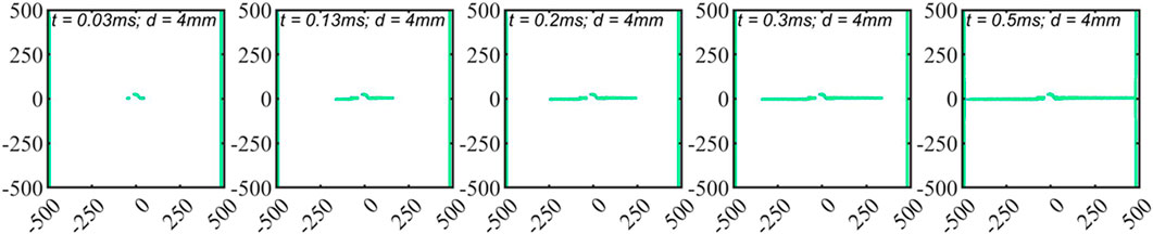
FIGURE 5. Crack propagation process diagram.
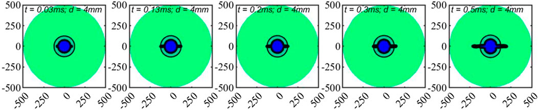
FIGURE 6. Motion of material particles in the process of pre-cracking process.
Figure 7 shows the Von Mises’s stress cloud map. It is seen that the maximum equivalent stress always occurs near the blasting hole. At 0.03 ms, the two initial cracks in the direction of energy accumulation at 0o and 180o started to expand significantly. At 0.13 ms, high-stress concentration can be observed at the crack tip, and stress waves propagate outward. At 0.2 ms, stress waves are reflected and superimposed, and the crack tip accelerates forward. The high-stress zone also weakens with time due to the continuous release of crack propagation energy.
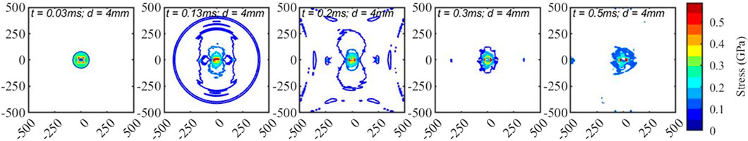
FIGURE 7. Variation of equivalent stress field during pre-cracking process.
Figure 8 shows the relationship curve between crack propagation length and angle under different hole diameters. When d =2 mm, crack cracking is limited to a small range around the blast hole, indicating that the shaped charge tube restricts the initiation and development of directional cracks. When d = 4 mm, the directional crack achieves good penetration, and the linear effect is good. The cracks in the 0° and 180° directions are controlled within the offset range of 2°. When d = 6 mm and 8 mm, accompanying cracks of 188° and 203° also appeared in addition to the initiation and penetration of directional cracks, respectively. In addition, the average deviations of cracks in these two cases were 4.2° and 2.3°, respectively. For d = 10 mm and 12 mm, crack penetration cannot be achieved, although longer linear cracks can still appear in the direction of the energy accumulation. The displacement of the cracks in the direction of the energy accumulation further expands, reaching 10.2° and 6.1°, and the length of the half cracks also increases. As d increases, the crack propagation length decreases in the direction of energy accumulation. The crack propagation in the right direction of energy accumulation only reaches 167 mm when d = 20 mm.
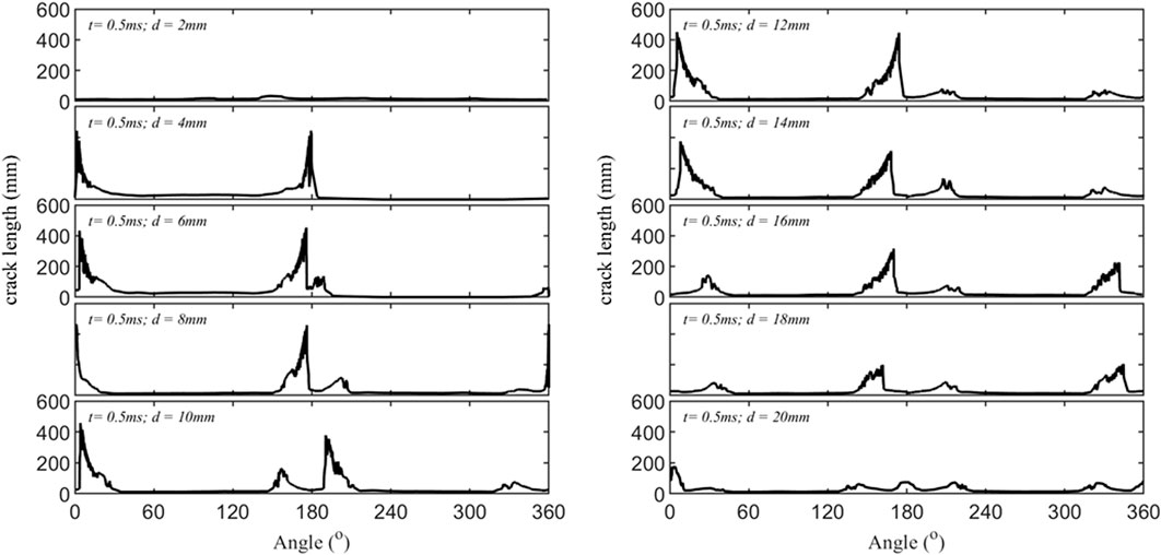
FIGURE 8. Correlation curves between crack length and cracking angle for different opening diameters (t = 0.5 ms).
Thus, it is deduced that the diameter of the shaped energy hole for biaxial tensile shaped charge blasting should be between 4 mm and 10 mm in order to form a linear crack, and the shaped energy cracking effect is optimal at 4 mm diameter, with the linear crack being the best.
The intuitive process of crack cracking in bi-directional cumulative tension blasting under different shaped charge hole diameters is shown in Figure 9. It can be seen that the crack only develops around the blast hole and does not form a linear crack when d = 2 mm. When d = 4 mm, the crack has a good linear shape and achieves continuity in the calculation area. For d = 6 mm and 8 mm, the cracks still exhibit a particular linear shape, except for deflection and accompanying cracks in the direction of 188°. Symmetrical airfoil cracks of varying lengths appear on the left and right sides as d increases. Although the cracks have a certain straightness at d = 10 mm and 12 mm, they do not penetrate. The crack length continuously decreases and deviates from the direction of the energy accumulation hole for d = 14 mm. When d = 20 mm, the crack propagation length in the right energy accumulation direction is already below 200 mm, whereas the crack propagation length in the left energy accumulation direction is merely 78.9 mm. Thus, the effect of biaxial tensile energy accumulation cracking is poor.
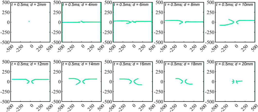
FIGURE 9. Final morphology of crack propagation under different opening diameters (t = 0.5 ms).
Figure 10 shows the distribution patterns of rock, shaped charge tube, and explosive particles at t = 0.5 ms under different hole diameters (opening). For d = 2 mm, the explosive particles are constrained within the shaped charge tube and do not attack the rock interior. The explosive particles pass through the shaped charge tube and directly enter the rock crack for d = 4 mm. The deepest invasion depth of the explosive particles reaches 230 mm, indicating that the explosive particles themselves, as a high-pressure gas, also enter the rock crack to drive the crack forward, called the “wedge” effect. When d = 6 mm and 8 mm, the maximum invasion depths of explosive particles are 200 mm and 165 mm, respectively. The direction of movement of explosive particles also confirms that biaxial tensile shaped charge blasting has a good linear pre-splitting effect in this case. After d = 10 mm, the area where the explosive particles come into contact with the rock also increases due to the continuous increase of the diameter of the shaped charge hole. The positions where the explosive particles enter the rock are mainly at both ends of the hole diameter, and the explosive particles do not significantly invade the rock matrix in the pre-splitting direction, resulting in wing-shaped cracks, which cannot achieve a significant linear pre-splitting effect.
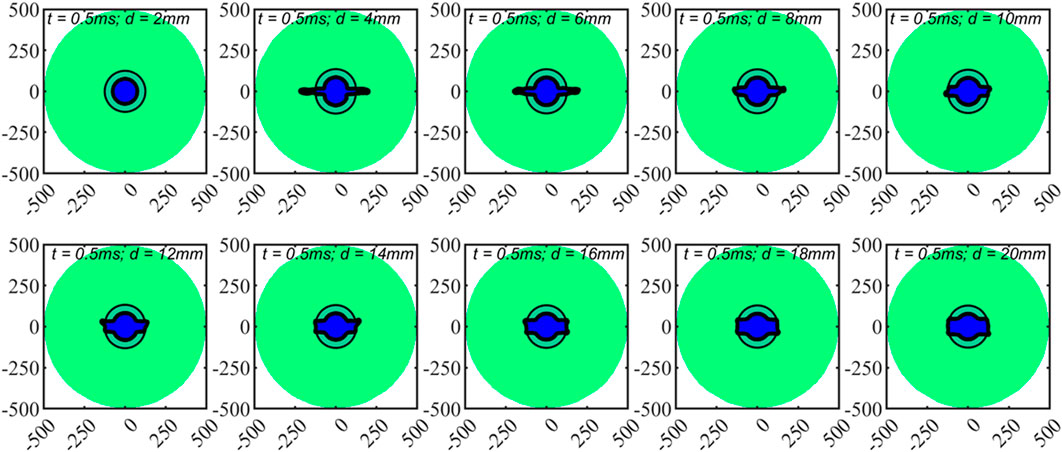
FIGURE 10. Final morphology of material particle motion under different accumulation hole diameters (t = 0.5 ms).
In summary, the linear effect of biaxial tensile shaped charge blasting is optimal when d = 4 mm, followed by the linear effect of biaxial tensile shaped charge blasting when d = 6 mm and 8 mm. However, the explosive particles can enter the crack well in both cases, further accelerating crack propagation.
The mechanism of the influence of energy accumulation hole on bi-directional cumulative tension blasting is a complex issue involving multiple physical and chemical processes. In bi-directional cumulative tension blasting, the design and processing of energy accumulation holes have a crucial impact on the blasting effect. The diameter of the energy accumulation hole determines the initial energy density of the bi-directional cumulative tension blasting and directly determines the initial penetration depth of the bi-directional cumulative tension blasting.
In the simulations of this study, good linear pre-cracking effects were obtained when the diameter of the energy accumulation hole was between 4 mm and 10 mm. When the diameters of the energy accumulation hole are less than 4 mm, the blasting effect is similar to that of conventional blasting. When the diameters of the energy accumulation hole are greater than 10 mm, the linear pre-cracking effect begins to decrease. There are two main reasons for these phenomena: Firstly, in terms of energy density, the energy density passing through the energy accumulation hole varies with different diameters. When the diameters of the energy accumulation hole are less than 4 mm, the energy passing through is insufficient, resulting in no effect. When the diameters of energy accumulation hole are greater than 10 mm, the energy density passing through the energy accumulation hole is dispersed due to the enlargement of the hole, resulting in cracks appearing at locations with larger curvature, such as symmetrical wing-shaped cracks. When the diameters of the energy accumulation hole are between 4 mm and 10 mm, the energy density passing through the energy accumulation hole is most suitable. Secondly, in terms of the mechanism of explosive driving, when the diameters of the energy-concentrating hole are between 4 mm and 10 mm, the surrounding rock has better penetration depth in the energy-concentrating direction, and the internal pressure exerted on the surrounding rock forms a tensile effect in the energy-concentrating direction, which is more favorable for crack propagation.
Figure 11 demonstrates the practical implementation of bi-directional cumulative tension blasting in the field. It is evident that bi-directional cumulative tension blasting effectively achieves directional pre-splitting when the parameters are appropriately designed, resulting in linear cracks. The bi-directional tensile shaped energy blasting also maintains a reasonable half-hole rate during on-site roof cutting in coal mines. This ensures the suitability of the roof-cutting pressure relief and self-forming roadway technology without the need for coal pillars.
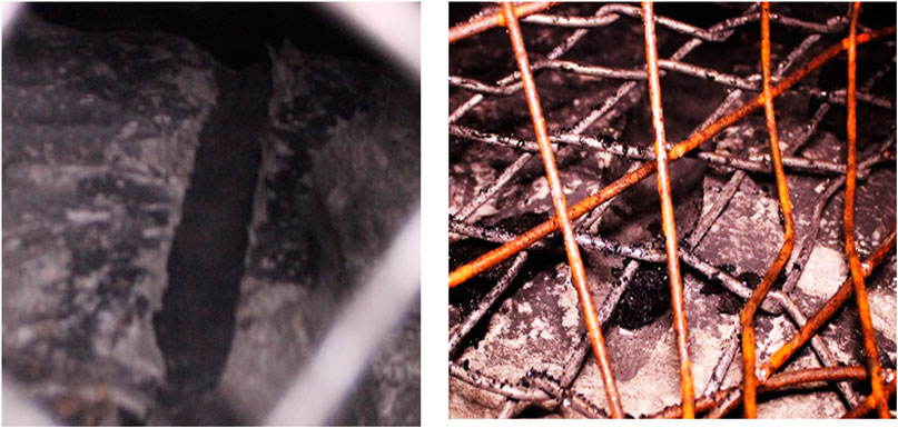
FIGURE 11. On site application of bi-directional cumulative tension blasting.
Smoothed Particle Hydrodynamics method was employed to investigate the pre-splitting mechanism and crack propagation of bi-directional cumulative tension blasting under varying energy accumulation hole diameters. The following key findings were derived from the obtained results:
1) The initial penetration depth of explosive particles was determined through analysis and incorporated into the fracture mechanics model for bi-directional cumulative tension blasting crack propagation. Fracture mechanics criteria were derived to drive crack propagation, and a Smoothed Particle Hydrodynamics model was established for bi-directional cumulative tension blasting.
2) The diameter of the energy accumulation hole has a direct impact on the directional pre-splitting effect of bi-directional cumulative tension blasting. Optimal linear pre-splitting is achieved when the diameter of the energy accumulation hole is 4 mm, followed by 6 mm and 8 mm. If the diameter of the energy accumulation hole is less than 4 mm or exceeds 8 mm, the directional pre-splitting length and angle in the direction of the shaped charge are compromised. Moreover, larger diameters result in a diminished effect of bi-directional cumulative tension blasting.
3) On-site tests of bi-directional cumulative tension blasting demonstrate that, with appropriate parameter design, this blasting technique yields favorable seam formation, validating the feasibility and practicality of bi-directional charge tension blasting.
These findings provide valuable insights into the design and optimization of bi-directional cumulative tension blasting, highlighting its potential for effective seam formation in practical applications.
The original contributions presented in the study are included in the article/Supplementary material, further inquiries can be directed to the corresponding author.
XZ: Writing–original draft, Writing–review and editing. YJ: Writing–original draft, Writing–review and editing. PZ: Conceptualization, Writing–original draft. ZZ: Methodology, Writing–original draft, Writing–review and editing. XH: Data curation, Writing–original draft.
The author(s) declare financial support was received for the research, authorship, and/or publication of this article. This work was supported by the funding of the Basic Research Program of Guizhou Province-ZK (2022) General 166, the Teaching Content and Curriculum Reform Project of Higher Education Institutions in Guizhou Province (2022304), University Student Innovation and Entrepreneurship Training Program Project (202210668002), Bijie City Science and Technology Project, Joint Fund Project ((2023) 54).
Author XH was employed by Ningxia Hongdunzi Coal Ind Co., Ltd.
The remaining authors declare that the research was conducted in the absence of any commercial or financial relationships that could be construed as a potential conflict of interest.
All claims expressed in this article are solely those of the authors and do not necessarily represent those of their affiliated organizations, or those of the publisher, the editors and the reviewers. Any product that may be evaluated in this article, or claim that may be made by its manufacturer, is not guaranteed or endorsed by the publisher.
Cao, J., Yang, X., Huang, R., Fu, Q., and Gao, Y. (2021). Research and application of directional roof cutting and pressure releasing technology for retracement channel of 3314 working face in Hexi coal mine. Res. Square. doi:10.21203/rs.3.rs-449704/v1
Chen, S. (1998). Modern drilling and blasting theory and technolog. Beijing, China: Coal Industry Press.
Chen, yiwei (1991). Determination of parameters for slot blasting. Metal. Mine 12, 26–31. CNKI:SUN:JSKS.0.1991-12-006.
Deng, Y., Ma, H., Wang, L., Zhang, Z., Wang, Y., Shen, Z., et al. (2020). Experiment research and application of borehole-blasting of spiral tube shape charge. J. Vib. Shock 39 (12), 63–69. doi:10.13465/j.cnki.jvs.2020.12.009
Du, H. (2017). Hydraulic roof fracturing technology and its application in upper corner of mining face. Coal Eng. 49 (12), 86–89. doi:10.11799/ce201712023
Gao, K., Liu, Z., Liu, J., Zhu, F., Qiao, G., Zhang, S., et al. (2019). Application research of directional cumulative blasting for weakening reverse faults in fully mechanized excavation face. Chin. J. Rock Mech. Eng. 38 (07), 1408–1419. doi:10.13722/j.cnki.jrme.2018.1447
Guo, D., Lv, P., Pei, H., Shan, Z., et al. (2012). Numerical simulation on crack propagation of coal bed deep-hole cumulative blasting. J. China Soc. 37 (02), 274–278. doi:10.13225/j.cnki.jccs.2012.02.027
Guo, D., Lv, P., Shan, Z., Xie, A., et al. (2013). Drilling parameters of deep-hole cumulative blasting to improve coal seam permeability in gas drainage. J. Univ. Sci. Technol. Beijing 35 (01), 16–20. doi:10.13374/j.issn1001-053x.2013.01.006
Guo, D., Lv, P., Wang, Y., Yang, R., et al. (2013). Blasting parameter study of deep-hole cumulative blasting to improve coal seam permeability. J. Univ. Sci. Technol. Beijing 35 (12), 1533–1537. doi:10.13374/j.issn1001-053x.2013.12.004
Guo, D., Pei, H., Song, J., Qin, F., Liu, X., et al. (2008). Study on splitting mechanism of coalbed deep-hole cumulative blasting to improve permeability. J. China coal Soc. 33 (12), 1381–1385. doi:10.13225/j.cnki.jccs.2008.12.025
Guo, D., Shang, D., Lv, P., Wang, S., Wang, J., et al. (2013). Experimental research of deep-hole cumulative blasting in hard roof weakening. J. China Coal Soc. 38 (07), 1149–1153. doi:10.13225/j.cnki.jccs.2013.07.021
Guo, D., Song, W., Li, Z., Qin, F., Liu, X., et al. (2009). Research on splitting technical of coal bed deep-hole cumulative blasting to improve permeability. J. China coal Soc. 34 (08), 1086–1089. doi:10.13225/j.cnki.jccs.2009.08.021
Guo, D., Yang, X., Shan, Z., Lv, P., et al. (2011). Sealing technology of coal bed deep-hole cumulative blasting. J. Univ. Sci. Technol. Beijing 33 (07), 785–789. doi:10.13374/j.issn1001-053x.2011.07.007
Guo, D., Zhang, C., Zhu, T., Pan, J., et al. (2018). Effect of charge structure on deep-hole cumulative blasting to improve coal seam permeability. Chin. J. Eng. 40 (12), 1488–1494. doi:10.13374/j.issn2095—9389.2018.12.006
Guo, D., Zhang, H., Lv, P., Zhang, G., et al. (2014). Effect of fault on deep-hole cumulative blasting to improve coal bed permeability. J. Univ. Sci. Technol. Beijing 36 (10), 1281–1286. doi:10.13374/j.issn1001-053x.2014.10.001
Guo, D., Zhao, J., Lv, P., Zhai, M., et al. (2016). Dynamic effects of deep-hole cumulative blasting in coal seam and its application. Chin. J. Eng. 38 (12), 1681–1687. doi:10.13374/j.issn2095-9389.2016.12.004
Guo, D., Zhao, J., Lv, P., Zhu, T., et al. (2019). Effective fracture zone under deep-hole cumulative blasting in coal seam. Chin. J. Eng. 41 (5), 582–590. doi:10.13374/j.issn2095-9389.2019.05.004
Guo, D., Zhao, J., Zhang, C., Zhu, T., et al. (2018). Mechanism of control hole on coal crack initiation and propagation under deep-hole cumulative blasting in coal seam. Chin. J. Rock Mech. Eng. 37 (4), 919–930. doi:10.13722/j.cnki.jrme.2017.1038
He, M., Cao, W., Shan, R., Wang, S., et al. (2003). New blasting technology-bilateral cumulative tensile explosion. Chin. J. Rock Mech. Eng. 22 (12), 2047–2051. doi:10.3321/j.issn:1000-6915.2003.12.018
He, M. C., Zhang, X., and Zhao, S. (2017). Directional destress with tension blasting in coal mines. Procedia Eng. 191, 89–97. doi:10.1016/j.proeng.2017.05.158
Jiang, B., Xin, Z., Zhang, X., Deng, Y., Wang, M., Li, S., et al. (2023). Mechanical properties and influence mechanism of confined concrete arches in high-stress tunnels. Int. J. Min. Sci. Technol. 33 (7), 829–841. doi:10.1016/j.ijmst.2023.03.008
Kang, Y., Zheng, D., Su, D., Yan, B., Li, D., Wang, X., et al. (2015). Model of directional shaped blasting assisted with water jet and its numerical simulation. J. Vib. shock 34 (9), 182–188. doi:10.13465/j.cnki.jvs.2015.09.033
Li, Y., Yang, Y., and Xu, C. (2000). Study on model and production test of slotted cartridge blasting. J. Liaoning Tech. Univ. Nat. Sci. 19 (2), 116–118. doi:10.3969/j.issn.1008-0562.2000.02.002
Liang, H., Guo, P., Sun, D., Ye, K., Zou, B., Sun, Y., et al. (2020). A study on crack propagation and stress wave propagation in different blasting modes of shaped energy blasting. J. Vib. Shock 39 (04), 157–164+184. doi:10.13465/j.cnki.jvs.2020.04.020
Liu, A. (2020). Hydraulic fracturing roof cutting for roadway protection in contiguous coal seams. Coal Eng. 52 (4), 48–52. doi:10.11799/ce202004008
Liu, J., Liu, Z., Gao, K., Ma, Y., Li, Z., Guo, L., et al. (2014). Experimental study and application of directional focused energy blasting in deep boreholes. Chin. J. Rock Mech. Eng. 33 (12), 2490–2496. doi:10.13722/j.cnki.jrme.2014.12.014
Mu, C., Wang, H., Huang, W., Kuang, C., et al. (2013). Increasing permeability mechanism using directional cumulative blasting in coal seams with high concentration of gas and low permeability. Rock Soil Mech. 34 (09), 2496–2500. doi:10.16285/j.rsm.2013.09.027
Shen, F., Song, Y., Zhao, W., Zhao, S., Yang, J., Tian, Y., et al. (2023). Research on novel method of gob-side entry retaining under the synergistic effect of roof cutting and roadside filling in thick coal seams. Rock Mech. Rock Eng. 56, 7217–7236. doi:10.1007/s00603-023-03385-1
Song, Y., Li, X., and Guo, D. (2018). Numerical simulation of multi-hole and same delay time of cumulative blasting in coal seam and its application. J. China Coal Soc. 43 (S2), 469–474. doi:10.13225/j.cnki.jccs.2018.1095
Sun, Z., Zhang, Z., and Wang, Z. (2019). Application and research on hydraulic fracturing and cutting top pressure relief technology in large mining height retained roadway. Coal Sci. Technol. 47 (10), 190–197. doi:10.13199/j.cnki.cst.2019.10.025
Wang, E., Shi, Z., Xi, W., Feng, J., and Wu, P. (2022). Mechanism and application of roof cutting by directional energy-cumulative blasting along gob-side entry. Sustainability 14 (20), 13381. doi:10.3390/su142013381
Wang, S., and Youzhi, W. (1985). Fracture control in rock blasting. J. China Univ. Min. Technol. 14 (3), 113–120. CNKI:SUN:ZGKD.0.1985-03-015.
Wang, X., Zhang, D., Peng, S., Zhang, W., et al. (2011). A rapid excavation technology for shotcreting and bolting roadway in deep soft rock. J. Min. Saf. Eng. 28 (03), 415–419. doi:10.3969/j.issn.1673-3363.2011.03.015
Hua, X., Liu, X., Huang, Z., Yang, P., Ma, Y., et al. (2020). Stability mechanism of non-pillar gob-side entry retaining by roof cutting under the coupled static-dynamic loading. J. China Coal Soc. 45 (11), 3696–3708. doi:10.13225/j.cnki.jccs.2020.1023
Yang, R., Zhang, Z., Yang, L., Guo, Y., et al. (2013). Cumulative blasting experiment study of slotted cartridge based on hard-rock rapid driving technology. Chin. J. Rock Mech. Eng. 32 (02), 317–323. doi:10.3969/j.issn.1000-6915.2013.02.013
Yang, X., Yuan, D., Xue, H., Gao, Y., Tian, X., Qi, J., et al. (2021). Research on roof cutting and pressure releasing technology of cumulative blasting in deep and high stress roadway. Geotech. Geol. Eng. 39, 2653–2667. doi:10.1007/s10706-020-01649-z
Yin, Q., Liu, R., Jing, H., Su, H., Yu, L., and He, L. (2019). Experimental study of nonlinear flow behaviors through fractured rock samples after high temperature exposure. Rock Mech. Rock Eng. 52, 2963–2983. doi:10.1007/s00603-019-1741-0
Yin, Q., Wu, J., Jiang, Z., Zhu, C., Su, H., Jing, H., et al. (2022). Investigating the effect of water quenching cycles on mechanical behaviors for granites after conventional triaxial compression. Geomechanics Geophys. Geo-Energy Geo-Resources 8, 77. doi:10.1007/s40948-022-00388-0
Yin, Q., Wu, J., Zhu, C., He, M., Meng, Q., and Jing, H. (2021). Shear mechanical responses of sandstone exposed to high temperature under constant normal stiffness boundary conditions. Geomechanics Geophys. Geo-Energy Geo-Resources 7 (2), 35–17. doi:10.1007/s40948-021-00234-9
Zhang, J., Lin, C., Tang, H., Wen, T., Tannant, D. D., and Zhang, B. (2023). Input-parameter optimization using a SVR based ensemble model to predict landslide displacements in a reservoir area-A comparative study. Appl. Soft Comput. 150, 111107. doi:10.1016/j.asoc.2023.111107
Zhang, S. (1988). Basic principles of explosion. Beijing, China: National Defence Industry Press, 531–578.
Zhang, W. (2019). Advanced hydraulic fracturing and cutting technology for mining. Coal Technol. 38 (9), 32–34. doi:10.13301/j.cnki.ct.2019.09.009
Zhang, Z., and Xiao, Z. (2000). Fracture-controlled methods for shallow blasting in rock. Min. R D 20 (6), 37–40. doi:10.3969/j.issn.1005-2763.2000.06.014
Zhu, C., Hu, N., Zhang, X., He, M., Tao, Z., Yin, Q., et al. (2022). Numerical simulation of bi-directional cumulative tension blasting based on smoothed particle flow method. J. Central South Univ. Sci. Technol. 53 (6), 2122–2133. doi:10.11817/j.issn.1672-7207.2022.06.014
Zhu, C., Xu, J., He, M. C., Karakus, M., Zhang, W., and Wu, Y. (2024). Amplification of ground vibration on a rocky hill and its environs under cylindrical SH waves. Rock Mechanics and Rock Engineering. Springer, Berlin, Germany, doi:10.1007/s00603-023-03711-7
Keywords: bi-directional cumulative tension blasting, crack propagation, energy accumulation, smooth particle hydrodynamics method, numerical simulation, pre-splitting
Citation: Zhang X, Jiang Y, Zhao P, Zhao Z and Hao X (2024) Influence mechanism of the diameter of the energy accumulation hole on the bi-directional cumulative tension blasting. Front. Earth Sci. 12:1360647. doi: 10.3389/feart.2024.1360647
Received: 23 December 2023; Accepted: 20 February 2024;
Published: 04 March 2024.
Edited by:
Tao Wen, Yangtze University, ChinaReviewed by:
Zhongjun Ma, Southeast University, ChinaCopyright © 2024 Zhang, Jiang, Zhao, Zhao and Hao. This is an open-access article distributed under the terms of the Creative Commons Attribution License (CC BY). The use, distribution or reproduction in other forums is permitted, provided the original author(s) and the copyright owner(s) are credited and that the original publication in this journal is cited, in accordance with accepted academic practice. No use, distribution or reproduction is permitted which does not comply with these terms.
*Correspondence: Yijun Jiang, amlhbmd5aWp1bjIwMjNAMTYzLmNvbQ==
Disclaimer: All claims expressed in this article are solely those of the authors and do not necessarily represent those of their affiliated organizations, or those of the publisher, the editors and the reviewers. Any product that may be evaluated in this article or claim that may be made by its manufacturer is not guaranteed or endorsed by the publisher.
Research integrity at Frontiers
Learn more about the work of our research integrity team to safeguard the quality of each article we publish.