 Qiang Li
 Yan-Yang Tong
 Jin-Nan Wang
 Hui Xu
94% of researchers rate our articles as excellent or good
Learn more about the work of our research integrity team to safeguard the quality of each article we publish.
Find out more
ORIGINAL RESEARCH article
Front. Earth Sci., 20 June 2024
Sec. Geohazards and Georisks
Volume 12 - 2024 | https://doi.org/10.3389/feart.2024.1355767
This article is part of the Research TopicMonitoring, Early Warning and Mitigation of Natural and Engineered Slopes, volume IIIView all 17 articles
The Newmark method is a classic method for evaluating the permanent displacements of a slope under seismic loads. This study aims at proposing a three-dimensional nested Newmark method (3D-NNM) in the framework of the kinematic theorem of limit analysis. The classical three-dimensional rotational failure mechanism is discretized into a series of nested rotating wedges, each of which is subjected to a corresponding yield acceleration determined by employing the work rate balance, and each of which produces relative displacements under seismic excitations when it exceeds the yield acceleration. The total permanent displacement profile is further obtained by integration of the relative displacements from the slope toe to the slope crest. The obtained results show that the proposed 3D-NNM can effectively evaluate the permanent displacement profile of slopes under earthquakes, and the proposed 3D-NNM improves the Leshchinsky’s 2D nested Newmark method by 30.7%; the obtained total horizontal displacement at the slope middle height reduces with the number of nested blocks, but increases with the increasing of the slope-width-to-height ratios. Besides, the traditional Newmark method with a single sliding block tends to overestimate the permanent displacements of slope under seismic shakings.
Accurate assessment of slope deformations is a classical problem in geotechnical engineering, since it is key to assess the slope stability for resilience design in earthquake-prone regions (Du and Wang, 2013; Zhang et al., 2023; Zhang et al., 2024). The methods used for assessing seismically-induced permanent displacements of slopes include numerical simulations with finite element method and the Newmark-based sliding block approach (Jibson, 2011).
Numerical simulations are able to provide a realistic response regarding stresses and strains of real-world slopes during earthquakes but subjected to large computational burden (Du et al., 2023; Li et al., 2023). Because of its advantage of easy to use and practical rationality, the Newmark-based sliding block approach has been widely used to assess the seismic permanent displacements of a variety of engineering structures (Newmark, 1965; Saygili and Rathje, 2008; Leshchinsky, 2018; Mathews et al., 2019; Song et al., 2019; Zhou et al., 2019; Zheng et al., 2020). The Newmark s approach originally proposed by (Newmark, 1965) is able to give the permanent displacement of a pre-assumed translational rigid block with a linear sliding surface in a slope once the input acceleration of a seismic wave exceeds the yield acceleration of the slope at the limit equilibrium condition which is determined by the pseudo-static method. The Newmark-based sliding block approach was modified by many researchers by, for example, building empirical formulas that relate the Newmark displacement with the ground motion (e.g., Arias intensity) and the critical acceleration of a slope (Hsieh and Lee, 2011; Chousianitis et al., 2014; Zhu et al., 2024), accounting for the model uncertainty and soil variability in the probabilistic framework (Yegian et al., 1991; Du et al., 2018; Li et al., 2020; Pan et al., 2021), and extending the translational rigid block to a rotational rigid block with a curved sliding surface (Nadukuru and Michalowski, 2013). The rotational failure mechanism with a curved sliding surface of slopes under dynamic loadings was observed in centrifugal model tests (Kutter and James, 1989) and in shake table model tests (Wartman et al., 2005).
However, the traditional single-block Newmark approach suffers from the drawback of neglection of the presence of multiple shear zones or regions of dispersed shear movement inside the slope under dynamic loadings that were observed in physical model tests (Kutter and James, 1989; Wartman et al., 2005). Besides, the traditional Newmark method fails to consider the complex constitutive properties and the time-varying properties of the soil materials under seismic loads (Pang et al., 2018b; Pang et al., 2021; Xu et al., 2023; Lu et al., 2024). The theoretical deficiency may result in bias prediction on seismic slope deformations using the traditional single-block Newmark approach. In order to address this issue, Leshchinsky (Leshchinsky, 2018) proposed a new nested Newmark approach to assess the permanent displacements of slopes subjected to earthquakes, based on the builds upon the well-accepted Newmark sliding block approach. In the proposed nested Newmark approach, the sliding block is discretized by a series of nested critical failure wedges, each yielding a critical yield acceleration. The proposed nested Newmark approach has the benefit of considering multiple shear zones or regions of dispersed shear movements of a slope under seismic loadings. The conceptual nested Newmark approach attract significant attention in the geotechnical community, and many authors published subsequent articles (Song et al., 2019; Zhou et al., 2019; Zheng et al., 2020). Zheng et al. (Zheng et al., 2020) extended the Nested Newmark method from the limit equilibrium framework to the upper-bound limit analysis framework and studied the influences of soil dynamic responses (including slope height, soil shear wave velocity and input ground motion) on the permanent Newmark displacement of slopes. Song et al. (Song et al., 2019) proposed a multi-block sliding approach to calculate the permanent Newmark displacement of slopes by considering a series of rigid blocks and the interactions between two neighbouring sliding blocks. They found that the single-block Newmark method produces unconservative estimates of permanent displacements of a shallow sliding mass when a deep-seated sliding subsequently occurs in a slope subjected to earthquakes. Zhou et al. (Zhou et al., 2019) incorporated the tensile strength cut-off into the Nested Newmark method and studied the seismic slope permanent displacements in the light of the kinematical approach of limit analysis. They found that neglecting the tensile strength of soils may underestimate the permanent displacements of slopes subjected to an earthquake. The aforementioned researches extended the nested Newmark approach and provided valuable academic contribution to seismic displacement assessments of slopes during earthquakes. However, these researches failed to include the three-dimensional (3D) effect of a slope when assessing the permanent displacements using the Newmark approach. In real-word scenario, slope failure often exhibits three-dimensional feature (Michalowski and Drescher, 2009; Gao et al., 2013; Liu Y. et al., 2023). Three-dimensional stability analysis of slopes has attracted great attention in academia (Chen et al., 2023; Dai et al., 2023; Liu W. et al., 2023). This study aims to fill this gap. Three-dimensional displacement analysis of slopes subjected to seismic loads is investigated by using the Nested Newmark method.
This paper aims at proposing a three-dimensional nested Newmark method (3D-NNM) in the framework of the kinematic theorem of limit analysis. The second section presents the nested 3D rotational failure mechanism, together with the formulation of the yield acceleration and the relative displacement of each block. The 3D-NNM is compared with the original Nested Newmark method of Leshchinsky (Leshchinsky, 2018) in the third section, which is followed by performing parametric analysis on checking the influences of the number of nested blocks, the slope-width-to-height ratios, the peak ground acceleration and the slope inclination angle. This paper finally ends up with a conclusion in the last section.
It is practically necessary to assess and monitor geotechnical structure deformations under seismic loadings, which attract great attentions from researchers (Mi et al., 2023; Zhao et al., 2024). The Nested Newmark method, based on the classical Newmark single sliding method, originally proposed by Leshchinsky (Du et al., 2023), considers a two-dimensional translational failure model of a simple homogeneous slope at the ultimate limit state under a seismic excitation. In the Nested Newmark method (Du et al., 2023), the moving body with a linear sliding surface is discretized into multiple nested sliding wedges, each of which is subjected to a constant seismic yield acceleration assessed in the framework of limit equilibrium method. The original Nested Newmark method (Du et al., 2023) provides a prototype to assess post-earthquake slope movements, no matter what kind of failure mechanisms are involved. Generally, the original Nested Newmark method have four main procedures (Du et al., 2023): (1) discretizing the sliding body into a series of nested sub-bodies based on a given failure model; (2) evaluating the seismic yield acceleration of each nested body by using the pseudo-static method; (3) calculating the relative velocity of each nested body by employing the input of a given acceleration time history and the time-dependent exceedance of a yield acceleration at the given time, and obtaining the relative discplacement of each nested body by integrating the relative velocity over time increments; (4) assessing the cumulative displacement profile at the given time t by integrating the relative displacements along the slope height from the slope toe to the slope crest upwards. This paper aims to extend the Nested Newmark method to incorporate the three-dimensional rotational failure mechanism in the framework of the upper-bound limit analysis method. These four basic procedures are introduced below.
Figure 1 gives a schematic representation of a three-dimensional rotational failure mechanism proposed by Michalowski and Drescher (Xu et al., 2023) in a homogeneous soil slope subjected to the seismic shakings at the ultimate limit state. The slope inclination is represented by the angle β; the slope height and width are denoted respectively by H and B. The sliding soils are presumed to rotate around the horizontal axis OX with an angular velocity ω. The failure of homogeneous soils is characterized by Mohr-Column yield criterion whose shear strength is represented by the internal friction angle φ and the soil cohesion c. The soil unit weight is denoted by γ. The 3D rotational failure mechanism is composed of a 3D curved horn body and a plane-strain insert. The 3D curved horn body is split in half along its longitudinal symmetry plane, between which the plane-strain body is inserted. The plane-strain body is distinguished from the three-dimensional rotation body, when the slope width becomes large, which makes the three-dimensional analysis results reduce to two-dimensional analysis. Readers are referred to Michalowski and Drescher (Xu et al., 2023) for the details of constructing the three-dimensional failure mechanism.
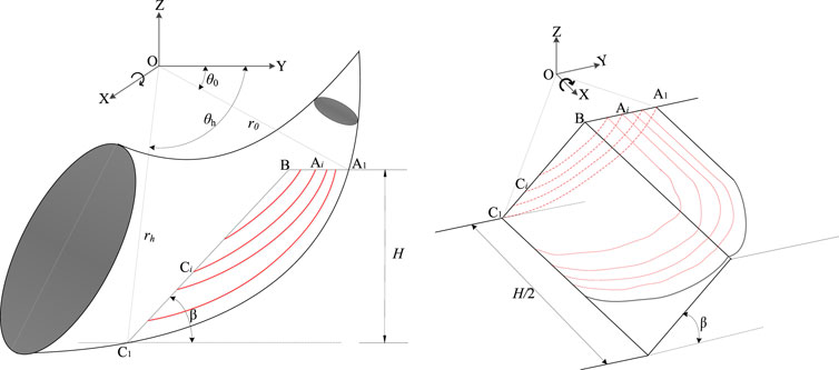
Figure 1. Nested 3D rotational failure mechanism.
The 3D rotational failure mechanism (Xu et al., 2023) is kinematically admissible on the condition that it obeys the plastic flow rule associated with the Mohr-Column yield criterion of soils. This requires that the geometrical shape of 3D rotational failure mechanism in the longitudinal symmetry plane is defined by two logarithmic spirals, the below one of which represents the sliding surface (see A1C1 in Figure 1). The logarithmic spiral of A1C1 is formulated as,
where r represents the radius of A1C1 to the rotational center O, the angle θ is measured from the horizontal plane, as sketched in Figure 1.
In the proposed 3D nested Newmark method, the sliding body bounded by the critical sliding surface A1C1 is discretized into N nested blocks, each of which is bounded by the sliding curved surface AiCi in the longitudinal symmetry plane, see Figure 1. For the i-th nested rotating block, the sliding surface AiCi in the longitudinal symmetry plane starts at the left hand at the point Ai-1 on the slope crest and ends above the point Ci-1 on the slope face, ensuring that nested sliding 3D body does not overlap. The profile in the longitudinal symmetry plane of the sliding curved surface AiCi is a logarithmic spiral whose rotational center may be different from the one of A1C1. It should note that the thickness of the sliding body bounded by the sliding curved surface Ai-1Ci-1 and the sliding curved surface AiCi tend to become infinitely small as the number of nested blocks become extremely large. This may enhance the predictive accuracy but cause a high computational burden in the proposed 3D nested Newmark method.
Making reference to Nadukuru and Michalowski (Du et al., 2018), the pseudo-static approach is firstly used to evaluate the critical seismic acceleration associated with the critical 3D curved sliding surface (the first nested body) in the framework of the upper-bound limit analysis. Based on the upper-bound limit analysis method, an upper-bound estimation of the seismic acceleration can be obtained by using the work balance equation, for which the external work rates are equal to the internal energy dissipations,
where
Once the critical seismic acceleration coefficient of the first nested body is determined, the critical seismic acceleration coefficient
Once the seismic acceleration kt from the acceleration-time history exceeds its critical value
where
With Eqs 1–4, the angular acceleration
The rotation angle of the i-th rotating nested 3D body,
in which
The horizontal seismic acceleration
In order to validate the proposed Nested Newmark method using 3D rotational failure mechanism, it is compared with the original Nested Newmark method of Leshchinsky (Du et al., 2023). Since that original Nested Newmark method of Leshchinsky (Du et al., 2023) considers a two-dimensional translational failure model, the ratio of slope width to its height is set to change from 2.0 to 10.0 in this study, which is large enough to allow the 3D failure mechanism reduce to 2D analysis. The model parameters regarding slope geometry and soil properties used in this paper are listed in Table 1. In the calculations, the nested blocks, which are evenly-spaced, are set to 150 in this section. The acceleration time history records of 1999 Chi-Chi earthquake, station TCU072-000 are taken for estimating post-earthquake slope deformations, which are also used in Leshchinsky (Du et al., 2023) and plotted in Figure 2.
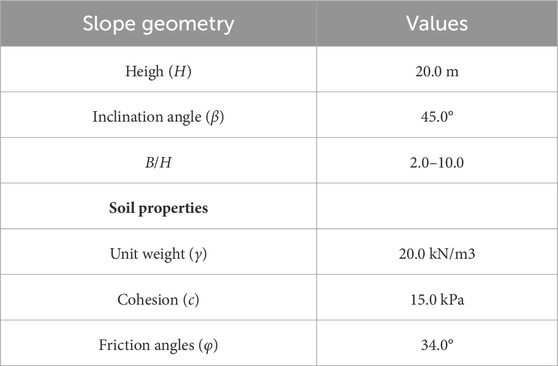
Table 1. Model parameters for comparisons.
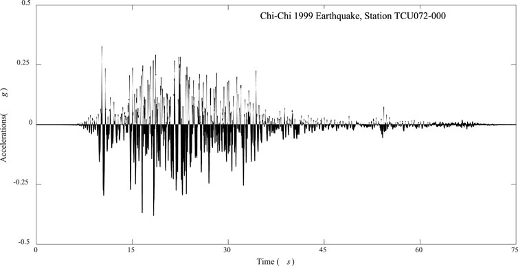
Figure 2. Acceleration time history records of 1999 Chi-Chi earthquake, station TCU072-000.
Figure 3 presents the relative displacement profiles along slope height provided by the proposed 3D nested Newmark method and by Leshchinsky (Du et al., 2023). It is observed both in the proposed 3D-NNM method and in Leshchinsky’s 2D model that the relative displacements decrease from the slope base towards the slope crest, and are close to zero above the slope height midpoint. This means that the slope above the slope height midpoint does not produce relative deformations, and its final deformations is purely caused by the sliding of underlying nested blocks. For example, the slope relative displacements, estimated by the proposed 3D-NNM method for the case of B/H being 5.0, increase from 0.05 m at the slope height of 5.0 m–0.22 m at the slope base. Besides, it is interesting to see that the relative horizontal displacements along the slope height of the Leshchinsky’s 2D nested Newmark method tends to be bigger than the solutions estimated by the proposed 3D nested Newmark method.
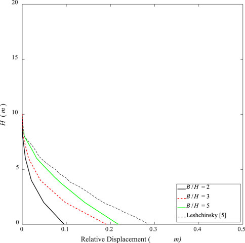
Figure 3. Relative horizontal displacement profiles along slope height for the two models.
Figure 4 presents the total horizontal permanent displacement profiles along slope height estimated by the proposed 3D-NNM method and given by the Leshchinsky’s 2D model (Du et al., 2023). The solution of the classical single-sliding block Newmark method is also plotted in the figure for a comparison. In contrast to the relative displacements, the final permanent displacements estimated both by the proposed method and by Leshchinsky (Du et al., 2023) increase from the slope base towards the slope crest, and tends to remain stable above the slope height midpoint. The maximum total horizontal permanent displacement estimated by the Leshchinsky’s 2D nested Newmark method (Du et al., 2023) is around 1.34 m, while it reaches 0.50 m when B/H = 2.0 and 1.08 m when B/H = 5.0 for the proposed 3D nested Newmark method. This indicates that the Leshchinsky’s 2D nested Newmark method may overestimate the post-earthquake deformation profile of slopes. The proposed 3D nested Newmark method improves the Leshchinsky’s 2D nested Newmark method by 30.7%, due to the fact that the proposed method yields a rigorous upper-bound estimation to the post-earthquake deformations. This divergence is due to the fact that the proposed 3D-NNM assumes a three-dimensional velocity field while Leshchinsky’s 2D model (Du et al., 2023) takes a translational velocity field. The finding agrees well with the statement that 2D analysis of slope stability delivers more conservative results compared with 3D analysis, which is well-known in the geotechnical community. Besides, the horizontal permanent displacement estimated by the classical single-sliding block Newmark method is only 0.25 m, which is smaller than the proposed 3D-NNM. This means that the traditional Newmark method with a single sliding block tends to underestimate the permanent displacements of slope under seismic shakings.
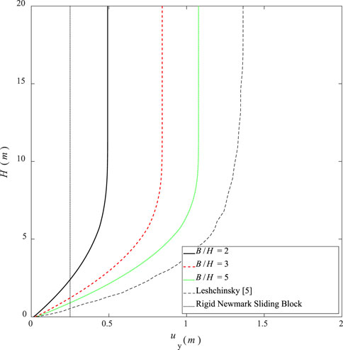
Figure 4. The total permanent displacement profiles along slope height for the two models.
This section discusses the influence of the number of nested blocks on the total Newmark displacement estimated by the proposed method. Figure 5 shows the profiles of the total horizontal displacements along the slope height for the number of nested blocks ranging between 10 and 200. It is seen that the number of nested blocks has a large influence on the estimated profiles of the total horizontal displacements along the slope height, which increases with the number of nested blocks. For example, the maximum total horizontal displacement at the slope crest is approximately 0.58 m for N = 10, and slowly converges around 1.08 m for N = 200, increasing by 86.2%. However, it should note that the computational burden is positively correlated with the number of nested blocks; the computational cost is around 3 min for the case of N = 10, but increases to around 20 min for the case of N = 200, on a desktop computer with a CPU of Core (TM) i5-12600K, 3.69 GHz. This means that the computational accuracy of the permanent displacements with more nested blocks is at the expense of high computational burden. Thus, in this paper, the number of nested blocks is set to 150 in the subsequent calculations to compromise between the computation burden and the computational accuracy.
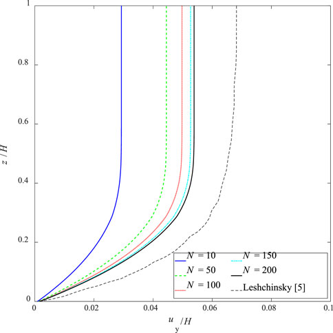
Figure 5. Influences of the number of nested blocks on total horizontal permanent displacement profiles.
This section aims to discuss the influences of the slope-width-to-height ratios, represented by B/H, on the seismic yield acceleration and the total horizontal displacement in the framework of the proposed Nested Newmark method. Figure 6 shows the profiles of seismic yield acceleration along the slope height for the B/H ratio changing from 2.0 to 20.0. For the case of B/H=3, the seismic yield acceleration increases from 0.18 g at the slope base to 0.42 g at the slope middle heigh, and finally raising to 2.0 g at the slope crest. Besides, at the slope middle heigh, the seismic yield acceleration decreases slightly with the increasing of the slope B/H ratio, which declines from 0.42 g at B/H=2 to 0.30 g at B/H=20.
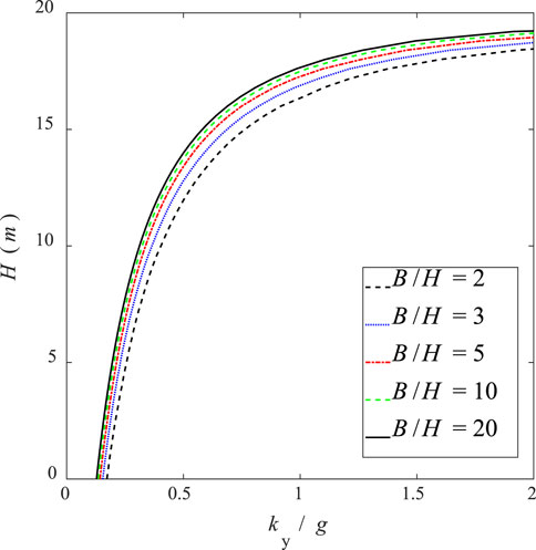
Figure 6. Influences of B/H ratio on the seismic yield acceleration profiles.
Figure 7 plots the profiles of the total horizontal displacements along the slope height for the B/H ratio changing from 2.0 to 10.0. For the case of B/H=3, the total horizontal displacement increases from 0.0 m at the slope base to 0.84 m at the slope middle heigh, beyond which the total horizontal displacement remains stable. This is because that the peak acceleration on the acceleration time history records of 1999 Chi-Chi earthquake, station TCU072-000, is around 0.375 g, as illustrated in Figure 1, which is smaller than the seismic yield acceleration at the slope middle height. Besides, the total horizontal displacement at the slope middle height increases with the increasing of the slope B/H ratio, which increases from 0.50 m at B/H=2 to 1.2 m at B/H=20. This phenomenon agrees well with what are observed in Nadukuru and Michalowski (Du et al., 2018), who assessed three-dimensional slope displacements under seismic loads using the traditional Newmark displacements.
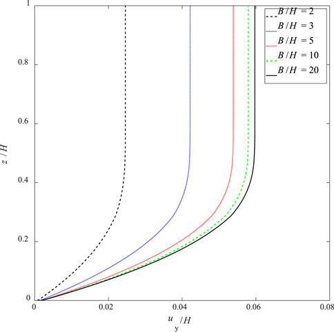
Figure 7. Influences of B/H ratio on the total horizontal displacement profiles.
This section studies the influences of the peak accelerations of ground motions, ac, on the seismically induced cumulative displacements of slopes by the proposed 3D-NNM. The peak ground acceleration time history records of 1999 Chi-Chi earthquake at station TCU072-000, plotted in Figure 2, are scaled to 0.40 g, 0.45 g, and 0.60 g, without changing the frequency. Figure 8 plots the profiles of the normalized total horizontal displacement profiles along the slope height for the peak accelerations of ground motions being 0.40g, 0.45g and 0.60 g. It is under expectation that the cumulative horizontal displacement profiles increase with the peak ground accelerations. Specially, the maximum cumulative horizontal displacement normalized the slope height is 0.055 for the case of ac = 4.0 g, and increases to 0.10 at 0.45 g and to 0.15 at 0.60 g. This indicates that the peak ground acceleration poses a great influence on the estimated cumulative horizontal displacements.
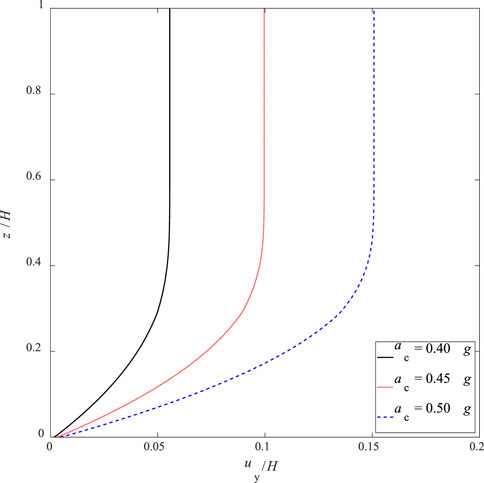
Figure 8. Influences of the peak ground accelerations on the total horizontal displacement profiles.
This section studies the influences of the slope inclination angles, β, on the seismically induced cumulative displacements of slopes by the proposed 3D-NNM. The slope inclination angles are set to change from 30° to 60°, with an increment of 15°. Figure 9 plots the profiles of the normalized total horizontal displacement profiles along the slope height for the slope inclination angles being 30°, 45° and 60°. It is observed that the cumulative horizontal displacement profiles are positively correlated with the slope inclination angles. Particularly, the maximum cumulative horizontal displacement normalized the slope height is 0.047 for the case of β = 30°, and increases to 0.53 at 45° and to 0.58 at 60°.
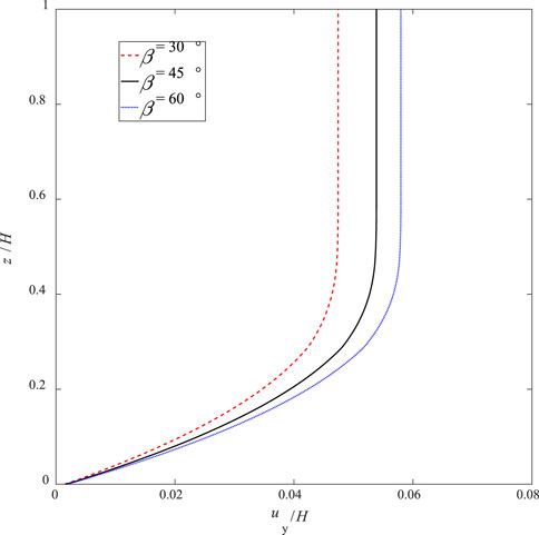
Figure 9. Influences of the slope inclination angles on the total horizontal displacement profiles.
This paper aims at proposing a three-dimensional nested Newmark method (3D-NNM) in the framework of the kinematic theorem of limit analysis. The proposed 3D-NNM is compared with the original Nested Newmark method, which shows that the proposed 3D-NNM can effectively evaluate the permanent displacement profile of slopes under earthquakes. The conclusions of this paper are summarized below:
(1) The proposed 3D-NNM is compared with the original Nested Newmark method of Leshchinsky (Du et al., 2023), whose work inspires this study. The comparisons are made with respect to the relative displacement profiles along slope height and the total horizontal permanent displacement profiles along slope height. Similar displacement profiles along slope height are observed both in proposed 3D-NNM and in the Nested Newmark method of Leshchinsky. It is interesting to find that the Leshchinsky’s 2D nested Newmark method may overestimate the post-earthquake deformation profile of slopes. Specifically, the maximum total horizontal permanent displacement is 1.34 m estimated by the Leshchinsky’s 2D nested Newmark method but is 1.08 m by the proposed 3D nested Newmark method with B/H = 5.0. This means that the proposed 3D nested Newmark method improves the Leshchinsky’s 2D nested Newmark method by 30.7%, since the proposed method gives a rigorous upper-bound estimation to the post-earthquake deformations.
(2) The performance of the proposed 3D-NNM is highly dependent on the number of nested blocks. It is interesting to find that the estimated total horizontal displacements converge after the number of nested blocks increase to 200. The higher the number of nested blocks, the better estimation of slope permanent displacements by the proposed 3D-NNM. However, the computational burden is positively correlated with the number of nested blocks. In order to balance the computation burden and the computational accuracy, the number of nested blocks is set to 150 in all the calculations in this study. This provides a way to determine the optimal number of nested blocks. The readers should note that the optimal number of nested blocks may be problem-dependent, but it is not difficult to determine the optimal one by following the above procedure. Besides, the traditional Newmark method with a single sliding block tends to underestimate the permanent displacements of slope under seismic shakings.
(3) The total horizontal displacement at the slope middle height increases with the increasing of the slope-width-to-height ratios. This further indicates that the two-dimensional analysis tends to provide conservative results of the proposed Newmark method.
It would be better if the proposed 3D-NNM could be compared with real-data experiments. However, a shaking table test of seismic slope stability is beyond the scope of this study. It will be the topic of future study of doing shaking table tests to check the presence of multiple shear zones or regions of dispersed shear movements of a slope subjected to seismic loads. Besides, two possible future research directions include: (1) the inclusion of reinforcement effect of soil nails in the proposed method, since soil nails are used to stabilize slopes in earthquake-prone zones; (2) considering the uncertainties of soil properties and seismic loadings that poses important influences on slope stability analysis.
The original contributions presented in the study are included in the article/Supplementary material, further inquiries can be directed to the corresponding author.
QL: Conceptualization, Methodology, Writing–original draft. Y-YT: Conceptualization, Software, Writing–original draft. J-NW: Software, Writing–review and editing. HX: Writing–review and editing.
The author(s) declare that financial support was received for the research, authorship, and/or publication of this article. The authors are very grateful for the financial support of the National Natural Science Foundation of China (Grant No. 42172309), and the Science Technology Department of Zhejiang Province (Grant No. 2022C03051).
The authors declare that the research was conducted in the absence of any commercial or financial relationships that could be construed as a potential conflict of interest.
All claims expressed in this article are solely those of the authors and do not necessarily represent those of their affiliated organizations, or those of the publisher, the editors and the reviewers. Any product that may be evaluated in this article, or claim that may be made by its manufacturer, is not guaranteed or endorsed by the publisher.
Chen, G., Zhang, K., Wang, S., Xia, Y., and Chao, L. (2023). iHydroSlide3D v1.0: an advanced hydrological-geotechnical model for hydrological simulation and three-dimensional landslide prediction. Geosci. Model Dev. 16, 2915–2937. doi:10.5194/gmd-16-2915-2023
Chousianitis, K., Del Gaudio, V., Kalogeras, I., and Ganas, A. (2014). Predictive model of Arias intensity and Newmark displacement for regional scale evaluation of earthquake-induced landslide hazard in Greece. Soil Dyn. Earthq. Eng. 65, 11–29. doi:10.1016/j.soildyn.2014.05.009
Dai, Z., Li, X., and Lan, B. (2023). Three-dimensional modeling of tsunami waves triggered by submarine landslides based on the smoothed particle hydrodynamics method. J. Mar. Sci. Eng. 11 (10), 2015. doi:10.3390/jmse11102015
Du, W., Huang, D., and Wang, G. (2018). Quantification of model uncertainty and variability in Newmark displacement analysis. Soil Dyn. Earthq. Eng. 109, 286–298. doi:10.1016/j.soildyn.2018.02.037
Du, W., and Wang, G. (2013). Intra-event spatial correlations for cumulative absolute velocity, Arias intensity, and spectral accelerations based on regional site conditions. Bull. Seismol. Soc. Am. 103 (2A), 1117–1129. doi:10.1785/0120120185
Du, Y., Xu, W., Han, W., Huang, B., Liu, H., and Du, X. (2023). Dynamic response analysis of wedge-shaped rock slopes under harmonic wave action. Buildings 13 (10), 2623. doi:10.3390/buildings13102623
Gao, Y. F., Zhang, F., Lei, G. H., and Li, D. Y. (2013). An extended limit analysis of three-dimensional slope stability. Géotechnique 63 (6), 518–524. doi:10.1680/geot.12.t.004
Hsieh, S. Y., and Lee, C. T. (2011). Empirical estimation of the Newmark displacement from the Arias intensity and critical acceleration. Eng. Geol. 122 (1-2), 34–42. doi:10.1016/j.enggeo.2010.12.006
Jibson, R. W. (2011). Methods for assessing the stability of slopes during earthquakes-A retrospective. Eng. Geol. 122 (1-2), 43–50. doi:10.1016/j.enggeo.2010.09.017
Kutter, B. L., and James, R. G. (1989). Dynamic centrifuge model tests on clay embankments. Geotechnique 39 (1), 91–106. doi:10.1680/geot.1989.39.1.91
Leshchinsky, B. A. (2018). Nested Newmark model to calculate the post-earthquake profile of slopes. Eng. Geol. 233, 139–145. doi:10.1016/j.enggeo.2017.12.006
Li, D. Q., Wang, M. X., and Du, W. (2020). Influence of spatial variability of soil strength parameters on probabilistic seismic slope displacement hazard analysis. Eng. Geol. 276, 105744. doi:10.1016/j.enggeo.2020.105744
Li, Y., Chu, Z., Zhang, L., and He, Y. (2023). Research on the dynamic response of a slope reinforced by a pile-anchor structure under seismic loading. Buildings 13 (10), 2500. doi:10.3390/buildings13102500
Liu, W., Zhou, H., Zhang, S., and Zhao, C. (2023b). Variable parameter creep model based on the separation of viscoelastic and viscoplastic deformations. Rock Mech. Rock Eng. 56, 4629–4645. doi:10.1007/s00603-023-03266-7
Liu, Y., Gao, Y., Shu, S., Dai, G., and Zhang, F. (2023a). Seismic stability and permanent displacement of 3D slopes with tension cutoff. Int. J. Geomechanics 23 (9), 04023158. doi:10.1061/ijgnai.gmeng-8697
Lu, Y., Pang, R., Du, M., and Xu, B. (2024). Simulation of non-stationary ground motions and its applications in high concrete faced rockfill dams via direct probability integral method. Eng. Struct. 298, 117034. doi:10.1016/j.engstruct.2023.117034
Mathews, N., Leshchinsky, B. A., Olsen, M. J., and Klar, A. (2019). Spatial distribution of yield accelerations and permanent displacements: a diagnostic tool for assessing seismic slope stability. Soil Dyn. Earthq. Eng. 126, 105811. doi:10.1016/j.soildyn.2019.105811
Mi, C., Liu, Y., Zhang, Y., Wang, J., Feng, Y., and Zhang, Z. (2023). A vision-based displacement measurement system for foundation pit. IEEE Trans. Instrum. Meas. 72, 1–15. doi:10.1109/TIM.2023.3311069
Michalowski, R. L., and Drescher, A. (2009). Three-dimensional stability of slopes and excavations. Géotechnique 59 (10), 839–850. doi:10.1680/geot.8.p.136
Nadukuru, S. S., and Michalowski, R. L. (2013). Three-dimensional displacement analysis of slopes subjected to seismic loads. Can. geotechnical J. 50 (6), 650–661. doi:10.1139/cgj-2012-0223
Newmark, N. M. (1965). Effects of earthquakes on dams and embankments. Geotechnique 15 (2), 139–160. doi:10.1680/geot.1965.15.2.139
Pan, Q. J., Leung, Y. F., and Hsu, S. C. (2021). Stochastic seismic slope stability assessment using polynomial chaos expansions combined with relevance vector machine. Geosci. Front. 12 (1), 405–414. doi:10.1016/j.gsf.2020.03.016
Pang, R., Xu, B., Zhou, Y., and Song, L. (2021). Seismic time-history response and system reliability analysis of slopes considering uncertainty of multi-parameters and earthquake excitations. Comput. Geotechnics 136, 104245. doi:10.1016/j.compgeo.2021.104245
Pang, R., Xu, B., Zou, D., and Kong, X. (2018b). Stochastic seismic performance assessment of high CFRDs based on generalized probability density evolution method. Comput. Geotechnics 97, 233–245. doi:10.1016/j.compgeo.2018.01.016
Saygili, G., and Rathje, E. M. (2008). Empirical predictive models for earthquake-induced sliding displacements of slopes. J. geotechnical geoenvironmental Eng. 134 (6), 790–803. doi:10.1061/(asce)1090-0241(2008)134:6(790)
Song, J., Fan, Q., Feng, T., Chen, Z., Chen, J., and Gao, Y. (2019). A multi-block sliding approach to calculate the permanent seismic displacement of slopes. Eng. Geol. 255, 48–58. doi:10.1016/j.enggeo.2019.04.012
Wartman, J., Seed, R. B., and Bray, J. D. (2005). Shaking table modeling of seismically induced deformations in slopes. J. Geotechnical Geoenvironmental Eng. 131 (5), 610–622. doi:10.1061/(asce)1090-0241(2005)131:5(610)
Xu, M., Pang, R., Zhou, Y., and Xu, B. (2023). Seepage safety evaluation of high earth-rockfill dams considering spatial variability of hydraulic parameters via subset simulation. J. Hydrology 626, 130261. doi:10.1016/j.jhydrol.2023.130261
Yegian, M. K., Marciano, E. A., and Ghahraman, V. G. (1991). Earthquake-induced permanent deformations: probabilistic approach. J. Geotechnical Eng. 117 (1), 35–50. doi:10.1061/(asce)0733-9410(1991)117:1(35)
Zhang, H., Xiang, X., Huang, B., Wu, Z., and Chen, H. (2023). Static homotopy response analysis of structure with random variables of arbitrary distributions by minimizing stochastic residual error. Comput. Struct. 288, 107153. doi:10.1016/j.compstruc.2023.107153
Zhang, X., Wang, S., Liu, H., Cui, J., Liu, C., and Meng, X. (2024). Assessing the impact of inertial load on the buckling behavior of piles with large slenderness ratios in liquefiable deposits. Soil Dyn. Earthq. Eng. 176, 108322. doi:10.1016/j.soildyn.2023.108322
Zhao, N., Li, D. Q., Gu, S. X., and Du, W. (2024). Analytical fragility relation for buried cast iron pipelines with lead-caulked joints based on machine learning algorithms. Earthq. Spectra 40 (1), 566–583. doi:10.1177/87552930231209195
Zheng, Z., Yufeng, G., Fei, Z., Jian, S., and Degao, Z. (2020). Effects of soil dynamic response on post-earthquake deformation of slopes based on nested Newmark model. Earthq. Eng. Eng. Vib. 19, 573–582. doi:10.1007/s11803-020-0581-y
Zhou, Z., Zhang, F., Gao, Y. F., and Shu, S. (2019). Nested Newmark model to estimate permanent displacement of seismic slopes with tensile strength cut-off. J. Central South Univ. 26 (7), 1830–1839. doi:10.1007/s11771-019-4137-0
Keywords: seismic slopes, Newmark displacements, kinematic theorem of limit analysis, three-dimensional, nested Newmark method
Citation: Li Q, Tong Y-Y, Wang J-N and Xu H (2024) Seismically-induced permanent displacements of slopes using 3D Nested Newmark method. Front. Earth Sci. 12:1355767. doi: 10.3389/feart.2024.1355767
Received: 14 December 2023; Accepted: 04 June 2024;
Published: 20 June 2024.
Edited by:
Wen Nie, Jiangxi University of Science and Technology, ChinaReviewed by:
Rui Pang, Dalian University of Technology, ChinaCopyright © 2024 Li, Tong, Wang and Xu. This is an open-access article distributed under the terms of the Creative Commons Attribution License (CC BY). The use, distribution or reproduction in other forums is permitted, provided the original author(s) and the copyright owner(s) are credited and that the original publication in this journal is cited, in accordance with accepted academic practice. No use, distribution or reproduction is permitted which does not comply with these terms.
*Correspondence: Hui Xu, eHVodWlAenN0dS5lZHUuY24=
Disclaimer: All claims expressed in this article are solely those of the authors and do not necessarily represent those of their affiliated organizations, or those of the publisher, the editors and the reviewers. Any product that may be evaluated in this article or claim that may be made by its manufacturer is not guaranteed or endorsed by the publisher.
Research integrity at Frontiers
Learn more about the work of our research integrity team to safeguard the quality of each article we publish.