 Zhigang Wang1
 Ziyang He
94% of researchers rate our articles as excellent or good
Learn more about the work of our research integrity team to safeguard the quality of each article we publish.
Find out more
ORIGINAL RESEARCH article
Front. Earth Sci., 15 March 2024
Sec. Geohazards and Georisks
Volume 12 - 2024 | https://doi.org/10.3389/feart.2024.1351978
Shallow utility tunnels with exceptionally large cross-sections in weak soil can face significantly more severe seismic risks compared to conventional deep tunnels in seismic hazard areas. This study investigates the seismic response and isolation technologies applied to a large section utility tunnel with 4 compartments in one layer, employing seismic simulations. The engineering context, dynamic motions, and measuring points of the numerical simulation were introduced. Subsequently, the finite element method was employed to explore the seismic behaviors of the large section utility tunnel when subjected to strong earthquake excitations under four conditions. The study explored and comparatively evaluated the seismic isolation effectiveness of three proposed schemes: the grouting scheme, the buffer layer, and the assembly of three-quarters buffer layer, cushion and grouting. The analysis included various indexes such as the deformation, the principal and shear stress, and the safety factor. The finding reveals that the assembly seismic scheme exhibits the most significant seismic effect (95.39%), followed by the buffer layer (38.82%), and the grouting scheme (25.66%). The assembly seismic scheme is recommended for the seismic design in the current large-section utility tunnels. These conclusions provide valuable scientific guidance for the seismic design of large-section utility tunnels, aiding in enhancing earthquake resilience.
Since the first utility tunnel was constructed in Paris, the continuous exploitation of municipal underground space has led to the emergence of a large number of underground pipeline tunnel projects (Canto-Perello and Curiel-Esparza, 2006). It is the key project and lifeline of municipal infrastructure to ensure the sustainable development of the city. The utility tunnels free up ground space, greatly improving the urban habitat and enhancing the city’s comprehensive carrying capacity (Broere, 2016; Xie et al., 2021). Large-section comprehensive utility tunnels have naturally become one of the trends in municipal underground engineering around the world (Luo et al., 2020; von der Tann et al., 2020). As the safety of its structure is the first priority to ensure the smooth flow of the city’s lifeline, providing basic conditions for late detection and maintenance, is an integral part of building a resilient city (Kourehpaz and Molina Hutt, 2022; Forcellini, 2023). Therefore, the study of seismic performance and response of utility tunnels has already become one of the hot directions of underground structure engineering.
The rectangular and multi-cabin layout design is common in China. Utility tunnels are large underground linear space structures, typically buried in the ground with trenching and backfilling in the past 20 years, such as in Guangzhou, 2004, Guangzhou higher education mega center, and Wuhan, 2009, Wangjiadun district (Wang et al., 2018). For the past long time, it has been widely believed that underground structures are constrained by the surrounding geotechnical constraints and are much safer than above-ground structures (Patil et al., 2018; Wang et al., 2021). In the great earthquakes of the last 30 years, researchers began to notice the damage to underground structures. The severe hazards in utility tunnels are quite different from those of above-ground structures, mainly manifested as concrete cracking or even destructing, disconnecting of various segments, soil liquefaction, as well as large deformation. The shallow buried municipal utility tunnel, with poor geological conditions, is vulnerable to suffering these serious catastrophes (Shen et al., 2014; Lu and Hwang, 2019; Sayed et al., 2019).
In response to the above seismic catastrophes of utility tunnels, many scholars conducted a lot of research on shallow municipal utility tunnels. Tsinidis focused on the numerical parametric to study the dynamic response of rectangular tunnels in soft soils (Tsinidis, 2017). Huang et al. (2023) obtained the refined seismic response by numerical modeling of utility tunnels for earthquakes in non-homogeneous sites (Darli et al., 2021). In addition, the multi-scale method (Yu et al., 2013) and three-dimensional nonlinear (Konstandakopoulou et al., 2021) were applied to analyze the seismic response under multiple earthquakes. Modeling tests are probably indispensable in the seismic response of utility tunnels. Yu et al. (2017) conducted a scaled-long tunnel to investigate the acceleration response of the tunnel and the deformation of tunnel joints. Cui and Ma (2021b) conducted a large 3D laboratory model test to study the deformation characteristic of the shallow loess tunnel. Due to the soaring growth of prefabricated structural technology, the seismic performance of prefabricated joints has also been focused on (Han et al., 2022; Li et al., 2022).
Currently, seismic isolation, energy dissipation and structural control are the three directional approaches to enhance seismic resistance (Zhou and Tan, 2018). Appropriately increasing the structure stiffness or the stability of the soil layer can effectively control underground structure displacements. Typical methods include the use of fiber concrete, high performance concrete, rock bolts, grouting and so on (Cui and Ma, 2021a). In terms of seismic isolation and energy dissipation, an appropriate isolation layer can significantly reduce seismic damage to tunnels. Rubber has been widely used as a material for buffers in the past. Zhou et al. (2023) applied pseudo-static methods to optimize the perforated rubber buffer layer in the tunnel. The hyperelastic composite and foamed products, such as asphalt sand, sponge rubber sheet, foam concrete and so on, are coated in the tunnel as a seismic layer as well. Ma et al. (2019) investigated the mechanical properties and associated seismic isolation effects of foamed concrete layer and carried out a parametric analysis using the Finite Element Method (FEM) to investigate the effect of the foamed concrete layer characteristics on the seismic isolation effect, including the density and thickness of the layer as well as the shear stiffness and residual friction coefficients at the interface. Using the shaking table test, Dai et al. (2023) investigated the factors affecting the glass fiber reinforced concrete (GFRC) isolation layer in the Xianglushan tunnel. Many deep buried tunnels have undergone research and implementation of measures to isolate and absorb vibrations. Numerous utility tunnel projects have been completed or are currently under construction in China. However, the development of shallow buried municipal utility tunnels with a large section is relatively slow. Although the above-ground structure was well studied, seismic risk zones were divided and the soil-structure interaction was considered, the relevant researches need to be conducted in the underground structure (Bolisetti et al., 2018; Forcellini, 2022). The seismic performance of utility tunnels has emerged as a critical issue that necessitates resolution during the promotion process. Previous studies have provided scientific guidance for the municipal utility tunnel in seismic active regions. The seismic response and resistance of large municipal utility tunnels need to be investigated, especially in weak soils. Such a large-section utility tunnel with four chambers in one layer is rare. In addition, severe earthquakes can trigger secondary disasters in utility tunnels. The expenses of maintaining and rebuilding are quite expensive. The structure safety of the utility tunnel under the severe earthquake cannot be ignored.
Therefore, in this paper, based on a shallow buried municipal utility tunnel with large section, the finite element method was used to explore its seismic response and seismic mitigation measures are optimized. The seismic effect of grouting and buffer layer were investigated on the following page. The paper compares three different isolation schemes and one non-isolation scheme. By studying their lining deformation, principal stress, shear stress and safety factor, it is concluded that the combination scheme has the best seismic performance. This research provides support for the isolation scheme of shallow buried large section public engineering tunnel. Meanwhile, this paper studies the seismic isolation technology of the shallow buried municipal utility tunnel, which fills the gap of a large number of researches on surface structure failure and insufficient research on underground structure failure in China.
Based on the urban precast utility tunnel project in Xiong’an New Area, Hebei Province, China, a seismic study of utility tunnels was carried out. It is characterized by large sections, long segments, and huge tonnage. The corridor truck and two 450 t rail-mounted gantry cranes were used in the construction process. The utility tunnel consists of four compartments with different functions to meet the future needs of the city for gas transmission, power supply, communication and water supply. The segments of the utility tunnel adopt prefabricated components, mainly made of C40 impermeable concrete. The shallow buried utility tunnel consists of four compartments in total, with an overall width of 13 m and a height of 4.2 m. The thickness of the middle partition wall is 0.3 m, and the top, bottom as well as side panels are all 0.5 m thick, as illustrated in Figure 1. The entire underground utility tunnel is equipped with an intelligent monitoring center, including closed-circuit television, smoke detection, and robotic inspection as well as temperature, humidity, toxic and hazardous gas monitoring. The tunnel is buried in a weak soil layer, which from top to bottom is plain backfill (3 m), silty clay (7 m), clay (20 m), and sand soil (10 m). This engineering is located in the area of seismic defense intensity is eight degrees and the design of the basic seismic acceleration is 0.3 g.
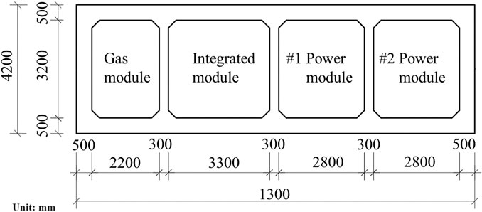
FIGURE 1. The large section utility tunnel (unit: mm).
In this paper, numerical simulations were carried out using ABAQUS software, a general-purpose finite element software, capable of solving relatively simple linear analyses and a wide range of complex nonlinear problems. The software is now widely used in several countries and plays a great role in the field of scientific research.
A series of preparations were made for the experiments. To explore the seismic resistance and damping technology for the large section utility tunnel, one seismic condition without any isolation scheme and three seismic conditions with any isolation scheme were adopted in the numerical simulation, as shown in Table 1. The thickness of the cushion and buffer layers is 0.1 m, made of C20 concrete and sponge rubber plate, respectively. In condition 2 and 4, cement sand grout is used around the perimeter of the tunnel in 3 m. Figure 2 plots the detailed profiles of four calculation conditions of the large section utility tunnel. The influence of surface buildings during earthquakes is not considered.
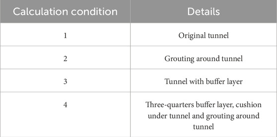
TABLE 1. Calculation conditions.
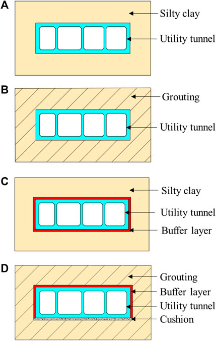
FIGURE 2. Calculation condition: (A) Condition 1, (B) Condition 2, (C) Condition 3, (D) Condition 4.
As illustrated in Figure 3, twenty-three monitoring points were arranged to the 2 m section of the segment. P1, P3, P5, P7, P9, P15, P17, P19, P21, P23 are at the joint where the plate meets the wall and P2, P4, P6, P8, P16, P18, P20, P22 are on the middle of the plate. P10-P14 are on the partition wall. The segment in the numerical model is 4 m long, as shown in Figure 4.
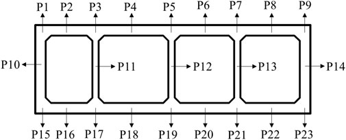
FIGURE 3. Monitoring point.
There are some basic assumptions before the numerical model.
(1) The surrounding rock and other materials are assumed to be isotropic and homogeneous.
(2) The traveling wave effect is not considered. A consistent excitation on the bottom is presumed.
(3) Static calculation, such as earth stress equilibrium only considers gravity.
(4) The liquefaction of sand and the impact of groundwater on the structure and soil are not considered.
To eliminate the boundary effect, the horizontal width on both sides of the utility tunnel in the model is taken as 3–4 times the tunnel width. The numerical model length is 90 m, with a vertical height of 40 m (shown in Figure 4). The buried depth from the ground to the top of the utility tunnel is 6 m. To simplify the calculation, it is assumed that the rock, utility segments, cushion, and buffer layer are homogeneous and isotropic materials. In this study, the Mohr-Coulomb model was selected for the surrounding rock and the concrete plastic damage model was selected for the concrete utility tunnel. The plastic model is applied to the damping layer.
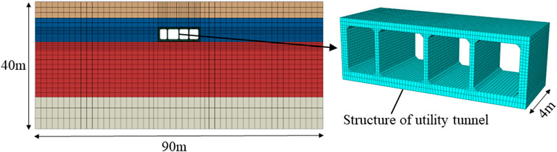
FIGURE 4. Numerical model.
The mesh size of the finite element model should not be larger than 1⁄8–1⁄10 of the highest frequency wavelength of the seismic wave. The computer performance, grid control method, and many trial calculations comprehensively determine the mesh size. Finally, the mesh size for the utility tunnel and the isolation scheme, such as the buffer layer and cushion, is 0.2–0.5 m. The surrounding rock around the utility tunnel is 0.5–1.0 m, while the mesh size of the other surrounding rock is 1.0–3.0 m.
The segment of the utility tunnel is made of C40 concrete. Rubber is used for buffer layers. Cement mortar is used for grouting. The cushion is made of C20 concrete. According to the geological investigation data, the physical and mechanical parameters of surrounding rocks, tunnel lining, buffer layer and cushion are shown in Table 2.
TABLE 2. Model parameter.
During seismic dynamic calculation in ABAQUS software, the CIN3D8 3D infinite units were employed to prevent seismic waves reflection. The static infinite element and dynamic viscous boundary were combined in the infinite element, arranging at the bottom of the model and around the model. Free field was applied to the top of the model. The displacement at the far point is assumed to be zero in static calculations. In dynamic calculations, three directional dampers were applied at the boundary and the rigid displacement was limited to prevent the viscous boundary drifting under low frequency. The original seismic waves were recorded from the Wolong station in the 2008 Wenchuan earthquake. Seismic waves were filtered and baseline corrected by SeismoSignal software, which lasted for 15 s. The displacement time history curve of the processed seismic waves is shown in Figure 5. The seismic wave acceleration time history curve is shown in Figure 6. According to the geological survey data, the spatial distribution of each soil layer is assumed to be shown in Figure 7. The seismic waves were released at the bottom of the model, as shown in Figure 7.
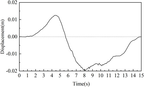
FIGURE 5. Displacements time history curve.
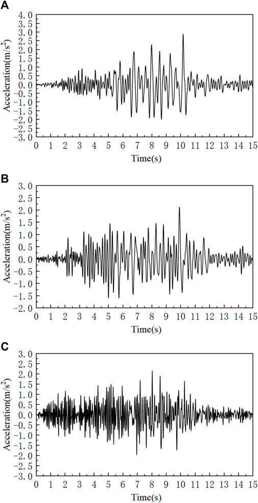
FIGURE 6. Time history curve of earthquake motion: (A) lateral load; (B) longitudinal load; (C) vertical load.
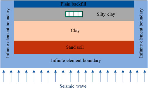
FIGURE 7. Seismic wave in model.
Through extraction and processing of data from the monitoring points, the deformation and stresses in the tunnel under different seismic conditions can be obtained. Several analyses are then made of the differences between one seismic condition without isolation scheme and three seismic conditions with isolation scheme.
As shown in Figure 8, the tendency of deformation remains consistent across all four conditions. Notably, the roof plates denoted as P2, P4, P6 as well as P8, exhibit the most substantial deformation, whereas the plates in the bottom of the large section utility tunnel experience comparatively minimal seismic-induced deformations. The utility tunnel is subjected to various actions during earthquakes, including forced displacement, seismic inertial forces, and soil loads. Seismic wave propagation to the bottom plate of the utility tunnel leads to the vibration of the soil below the bottom plate. The mechanical properties of the soil are greatly weaker than the bottom plate made of concrete, thus causing the interaction forces among the soil particles to be destroyed first. Meanwhile, the seismic waves are transmitted from the bottom plate to the roof plate in the process of amplification through the hollow compartments, which ultimately makes the dynamic response at the top plate greater than that of the bottom plate.
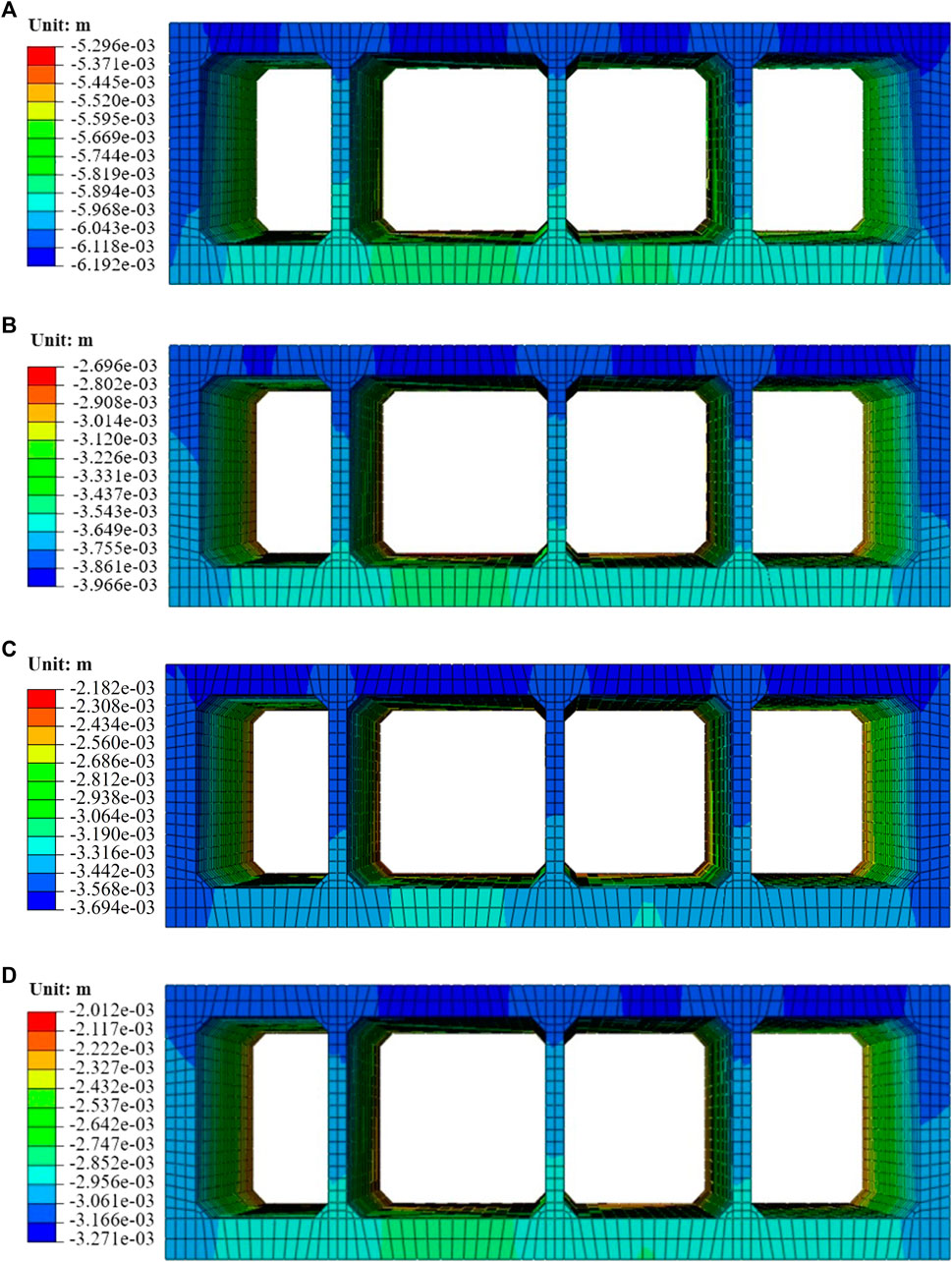
FIGURE 8. Deformation of the large section utility tunnel. (A) Original tunnel, (B) Grouting around tunnel, (C) Tunnel with buffer layer, (D) Three-quarters buffer layer, cushion under tunnel and grouting around tunnel. (Unit: m).
In short, the deformation of the lining roof is greater than that of the bottom plate in four conditions, but there are some differences. The deformation of the three conditions is reduced in comparison to Condition 1. Compared with the other three conditions, the buffer layer (Condition 3) narrowed the difference between the roof and the bottom plate. The presence of a damping layer facilitated a more uniform distribution of deformation.
In addition, the significant deformation at P4 in the roof plate was aggravated by the large spans associated with the four compartments. In Condition 1, the peak value of deformation occurs at P2, P4, P6, P8 and P9, measuring about 6.192 mm. In Condition 2, the peak deformation gets relieved at P2, P4, P6, and P8, measuring about 3.966 mm, after the implementation of grouting around. When the buffer layer was adopted in the large section utility tunnel, the maximum deformation exhibited a 35.95% reduction compared to Condition 1. Finally, the maximum deformation decreases to 3.271 mm in Condition 4. Consequently, the assembly of three-quarters buffer, cushion as well as grouting (i.e., Condition 1) exhibits the dramatical isolation effect (47.17%), followed by the buffer layer (40.34%) and the grouting scheme (35.95%), as summarized in Table 3.
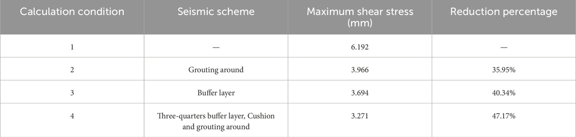
TABLE 3. The maximum deformation.
From Figure 8, the roof plate at P18 suffered severe deformation in four conditions. The plates of integrated modules have the largest span and are most susceptible to seismic hazards. As shown in Figures 9, 10, the deformation at P4 and P18 in the integrated module is similar to the seismic displacement response in Figure 4. In Condition 1, the maximum and minimum deformation at P4 and P18 is 25.99 mm, −45.54 mm, and 23.3 4mm, −40.04 mm, respectively. In Condition 2, it decreases to 20.73 mm, −35.52 mm, and 18.20 mm, −31.34 mm, respectively. When the buffer layer was employed, the maximum and minimum deformation at P4 and P18 dropped to 16.70 mm, −27.32 mm, and 13.78 mm, −24.02 mm, respectively. Finally, the maximum and minimum deformation at P4 and P18 decrease to 14.65 mm, −26.26 mm, and 10.65 mm, −19.09 mm, respectively. Three seismic isolation schemes reduced the deformation at P4 and P18 of the large section utility tunnel during strong seismic motions. It has a positive effect on protecting the equipment and pipelines inside the utility tunnel.
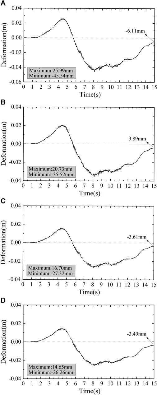
FIGURE 9. Time history curve of deformation at P4. (A) Condition 1; (B) Condition 2; (C) Condition 3; (D) Condition 4.
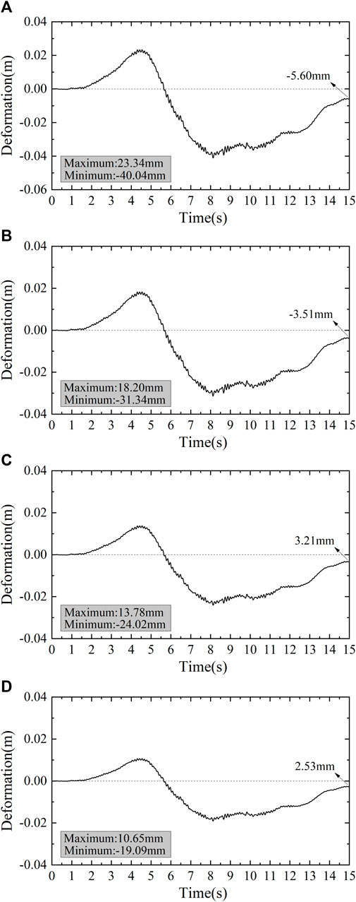
FIGURE 10. Time history curve of deformation at P18. (A) Condition 1; (B) Condition 2; (C) Condition 3; (D) Condition 4.
Figure 11A demonstrates the maximum principal stress of the large section utility tunnel under the severe earthquake. In this case, stress concentrations are frequently observed at the junction of the plate and wall, notably at P3, P5, P7, P17, P19 as well as P21. As underground structures, the stress response of the utility tunnel is mainly affected by soil displacements. The soli displacements result in the roof plate deformations, consequently increasing the principal stress concentrations at the junction. The restraining effect of soil becomes stronger as the depth increases in Condition 1. The shallow burial depth and weak soil restraint cause the highest maximum principal stress on the roof plate (P5). As shown in Figure 11B, grouting enhanced the binding force of soil and reduced the peak value of the maximum principal stress, but intensified the stress concentration at P7. In Figures 11C, D, the stress concentrations also occurred in the bottom plate (P19). The presence of a buffer layer reduces the constraint of soil on the bottom plate to a certain degree.
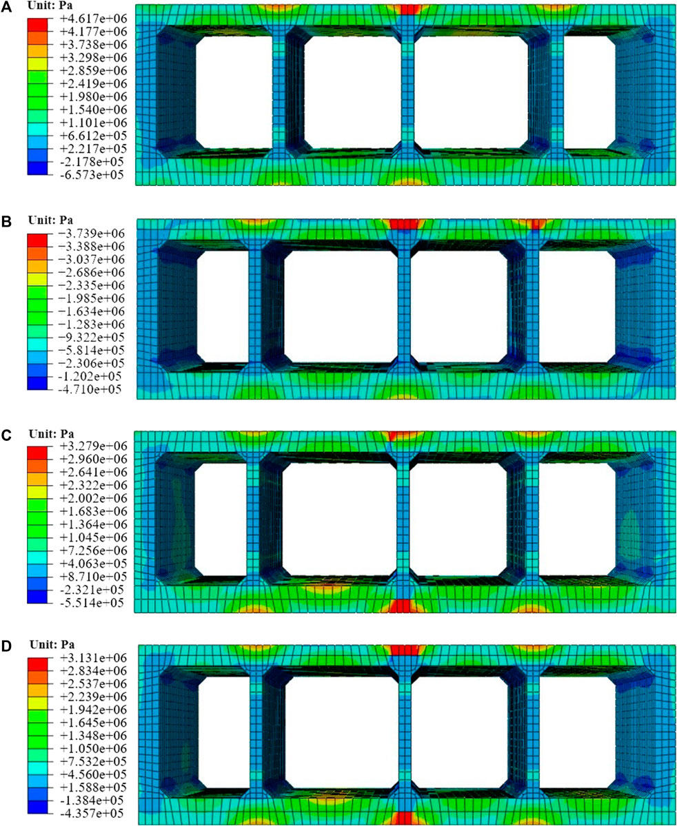
FIGURE 11. Maximum principal stress. (A) Original tunnel; (B) Grouting around tunnel; (C) Tunnel with buffer layer; (D) Three-quarters buffer layer, cushion under tunnel and grouting around tunnel. (Unit: Pa).
As shown in Table 4, three seismic conditions with the isolation scheme are compared to one seismic condition without isolation scheme. In Condition 1, the peak value of maximum principal stress in the large section utility tunnel is 4.617 MPa. Compared with Condition 1, it decreases to 3.739 MPa in Condition 2, representing a reduction of 19.02%. In Condition 3, when the utility tunnel was wrapped with a 0.1 m thick sponge rubber plate as the buffer layer, the peak value of the maximum stress decreased to 3.279 MPa, with a 28.98% reduction. Finally, when the three-quarters buffer, cushion as well as grouting were applied, the peak value was reduced to 3.131 MPa, which marks a significant reduction of 32.19% compared to Condition 1.
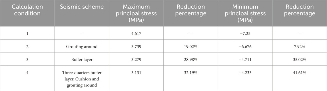
TABLE 4. The maximum and minimum principal stress.
The minimum principal stress distribution also shows stress concentrations, but not the same as the maximum principal stress case. Figure 12A reveals that stress concentrations of the minimum principal stress emerge repeatedly in the partition wall and some haunched corners, specifically near P11, P12, as well as P13. As shown in Figure 12B, grouting intensified the concentration at the haunched corner. While the buffer layer was implemented in Condition 3 and 4 (Figures 12C, D), it was alleviated.
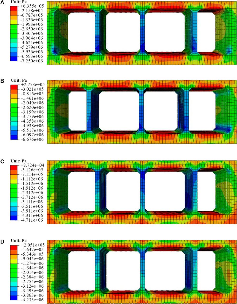
FIGURE 12. Minimum principal stress. (A) Original tunnel; (B) Grouting around tunnel; (C) Tunnel with buffer layer; (D) Three-quarters buffer layer, cushion under tunnel and grouting around tunnel. (Unit: Pa).
A comparison was made between three seismic conditions with isolation schemes and one seismic condition without an isolation scheme. The value of minimum principal stress peaks at 7.25 MPa in condition 1. With grouting around the tunnel in 3 m (i.e., Condition 2), the peak value of the minimum principal stress reduces to 6.676 MPa, indicating a 7.98% decrease. In Condition 3, where a buffer layer was coated, the peak value of the stress decreased to 4.711 MPa, marking a 35.02% reduction compared to the original tunnel stress. Moreover, with the implementation of a three-quarters buffer, cushion under the tunnel and grouting around in Condition 4, the value of minimum principal stress drops dramatically to 4.233, reflecting a remarkable reduction of 41.61% compared to Condition 1.
The principal stress and reduction percentage of three seismic schemes compared with Condition 1 for the large section utility tunnel is shown in Table 4. In terms of principal stress, the assembly of three-quarters buffer, cushion as well as grouting exhibits the dramatical isolation effect (41.61%), followed by the buffer layer (35.02%) and tunnel with grouting around (7.92%).
As shown in Figure 13, the highest value of structure shear stress appears after the seismic action. The concentration of the maximum shear stress is notably evident where the board meets the wall, particularly close to P3, P5, P7, P17, P19 as well as P21. Due to a single-story structure utility tunnel with a relatively small height (4.2 m) compared to four compartments with 13 m, The partition wall (0.3 m) is relatively thinner than the side wall (0.5 m). It leads to the maximum shear stress under different calculation conditions appearing at the partition wall, which is prone to damage. It is worth noting that the stress concentration in the original tunnel and the tunnel with grouting around primarily occurs at some corners and partition walls of the utility tunnel. However, in Condition 3 and Condition 4, it manifests merely in the middle partition walls. This behavior is attributed to the buffer layer not only diminishing the seismic impact on the structure but also promoting a more even distribution of forces, thereby reducing the occurrence of stress concentration.
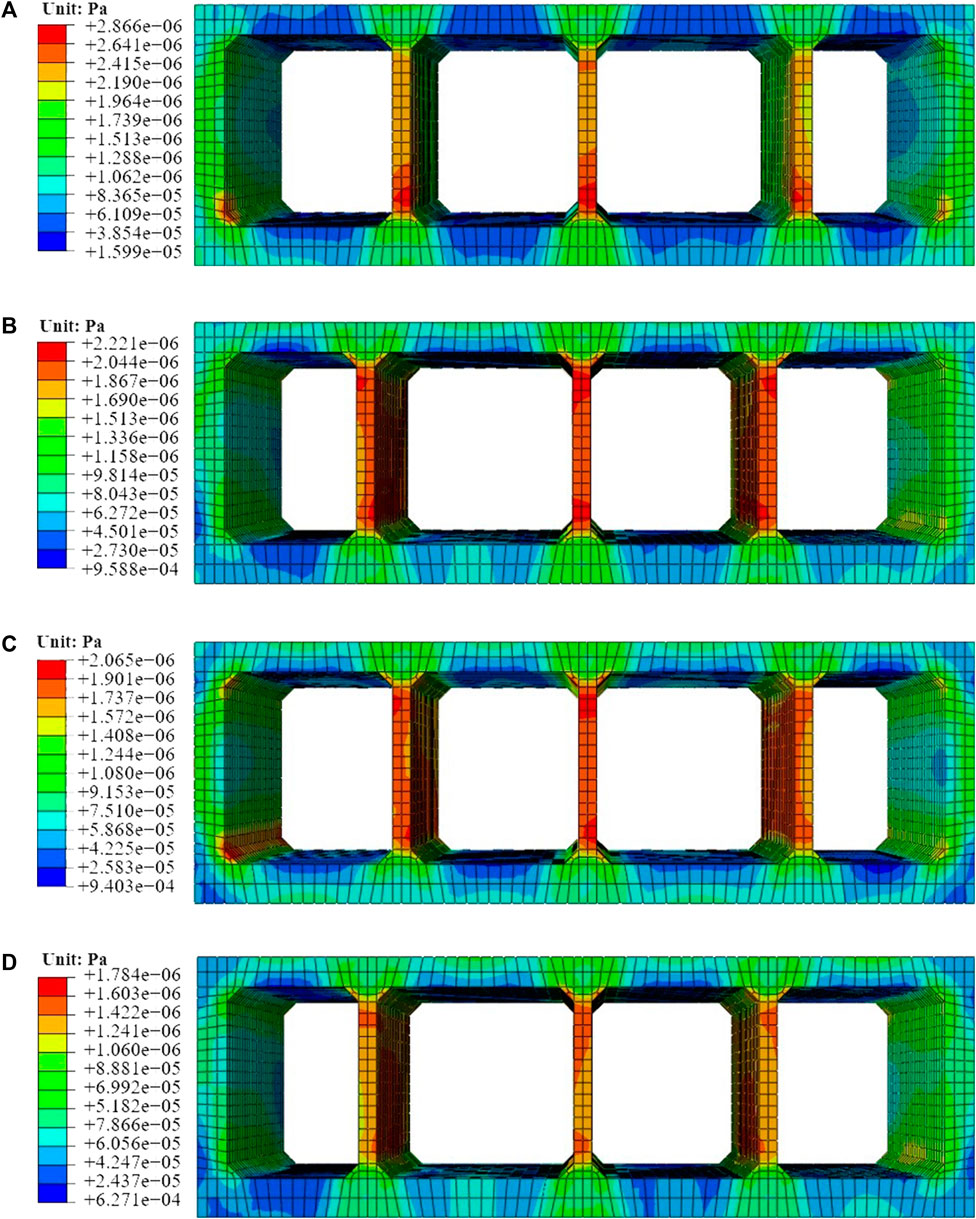
FIGURE 13. Maximum shear stress. (A) Original tunnel; (B) Grouting around tunnel; (C) Tunnel with buffer layer; (D) Three-quarters buffer layer, cushion under tunnel and grouting around tunnel. (Unit: Pa).
Similar to the deformation and principal stress, tunnel with grouting around, a buffer layer, and the assembly of three-quarters buffer, cushion as well as grouting all serve to relieve the seismic forces acting on the segments, leading to a reduction in the peak shear stress. The peak shear stress reaches 2.866 MPa for the large section utility tunnel with no seismic enhancements. Immediately, the value reduces to 2.221 MPa when the C25 concrete cushion is implemented, resulting in a 22.51% reduction. In Condition 3, the peak value of maximum shear stress decreases to 2.065, demonstrating a reduction of 31.86%, due to the adoption of the buffer layer for the large section utility tunnel. Furthermore, the peak shear stress experiences a remarkable reduction when the three-quarters buffer layer, cushion, and grouting are integrated into the seismic design, with a peak value of 1.784 MPa and a corresponding reduction of 37.75%. As outlined in Table 5, the assembly of three-quarters buffer, cushion as well as grouting exhibits the most effective seismic resistance and mitigation performance (22.51%), followed by the buffer layer (27.95%) and tunnel with grouting around (37.75%).
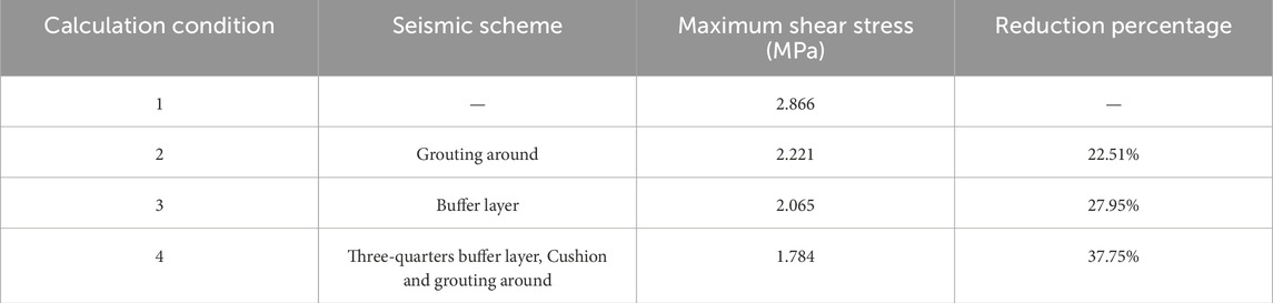
TABLE 5. The maximum shear stress.
In this paper, the safety factor in the Chinese Standard (China MOTOTPSRO, 2018) is referred to as the evaluation index of utility tunnel structure. According to the standard (China MOTOTPSRO, 2018), the safety factor can be calculated from Eqs 1, 2 under severe seismic motions. Theoretically, the performance of the tunnel seismic resistance and mitigation weakens as the safety factor decreases.
Where K—the safety factor; N—the maximum axial force; φ—component longitudinal bending coefficient; α—the influence coefficient of axial force eccentricity; Ra—ultimate compressive strength of concrete; Rl—ultimate tensile strength of concrete; b—width; h—thickness; e0—axial force eccentricity influence coefficient.
Figure 14 shows the safety factor of each monitoring point with four different seismic conditions during the strong earthquake. In four seismic conditions, the safety factors on the joint are lower than others and the minimum safety factor emerges where the roof plate meets the middle partition wall (i.e., at P15). For the tunnel without seismic scheme, the minimum safety factor is 1.52. It increases to 1.91 with a growth of 25.66%, compared to Condition 1, but several of safety factors remain lower than the safety factor limit (2.4). When the buffer layer was adopted in the large section utility tunnel, the minimum safety factor increased to 2.11, demonstrating an addition of 38.82%. However, the safety factor of P5 and P7 still do not satisfy the safety factor limit. Consequently, when three-quarters buffer, cushion as well as grouting were implemented, the minimum safety factor reached 2.97, satisfying the safety lower limit.
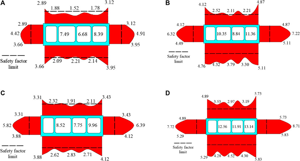
FIGURE 14. Safety factor. (A) Original tunnel; (B) Grouting around tunnel; (C) Tunnel with buffer layer; (D) Three-quarters buffer layer, cushion under tunnel and grouting around tunnel.
Taking the growth rate of the minimum safety factor as the seismic effect, the seismic effect under various conditions is demonstrated in Table 6. To sum up, the assembly of three-quarters buffer layer, cushion and grouting around possesses the most excellent seismic effect (95.39%), followed by the buffer layer (38.82%) and the grouting around (25.66%).

TABLE 6. Seismic scheme effect.
This study explores the seismic isolation schemes for the shallow buried and large section utility tunnel in soft soil in a seismic vulnerability zone in China. It examines various parameters under intense seismic forces, including lining deformation, principal stress, shear stress, and safety factors. The main purpose of the paper is to investigate the seismic effect of different seismic measures.
The study only investigates the seismic performance of three distinct approaches by uniform excitation. The utility tunnel is a long linear shallow buried structure, the research of non-uniform excitation and seismic performance of the joint can be carried out in the future. Moreover, the seismic performance of the pipeline inside the utility tunnel is not considered and can be supplemented in future studies. The model experiments or field experiments will be conducted in future work. While the study in this paper does not delve into the types and directions of seismic motion or theoretical derivations, it still yields noteworthy conclusions:
(1) Grouting and the buffer layer have a good effect on blocking the transmission of seismic force to the lining structure. The deformation and seismic force of the structure are improved.
(2) However, grouting caused stress concentration in the roof and the haunched corner of the utility tunnel to increase. Moreover, the buffer layer weakens the binding force of soil on the bottom of the utility tunnel.
(3) The safety factors of the utility tunnel with grouting and the buffer layer are remarkably increased. The seismic performance of the buffer layer is better than that of grouting.
(4) Compared to using only grouting or a buffer layer, the combination method significantly improves the seismic performance of the utility tunnel. The assembly of three-quarters buffer layer, cushion and grouting is recommended for use in the seismic design of the present large section utility tunnel.
The original contributions presented in the study are included in the article/Supplementary material, further inquiries can be directed to the corresponding author.
ZW: Writing–original draft. LC: Writing–original draft. HM: Writing–original draft. LZ: Writing–original draft. GC:Writing–review and editing. HS: Writing–original draft. ZH: Writing–original draft, Writing–review and editing.
The author(s) declare financial support was received for the research, authorship, and/or publication of this article. This work was supported by the National Natural Science Foundation of China (Grant Number: 52178378).
The authors gratefully acknowledge the financial support by the National Science Foundation of China under Grant Number: 52178378.
Authors LC, HM, and HS were employed by CCCC-SHEC West China Constructi on Co., Ltd.
The remaining authors declare that the research was conducted in the absence of any commercial or financial relationships that could be construed as a potential conflict of interest.
All claims expressed in this article are solely those of the authors and do not necessarily represent those of their affiliated organizations, or those of the publisher, the editors and the reviewers. Any product that may be evaluated in this article, or claim that may be made by its manufacturer, is not guaranteed or endorsed by the publisher.
Bolisetti, C., Whittaker, A. S., and Coleman, J. L. (2018). Linear and nonlinear soil-structure interaction analysis of buildings and safety-related nuclear structures. Soil Dyn. Earthq. Eng. 107, 218–233. doi:10.1016/j.soildyn.2018.01.026
Broere, W. (2016). Urban underground space: solving the problems of today’s cities. Tunn. Undergr. Space Technol. 55, 245–248. doi:10.1016/j.tust.2015.11.012
Canto-Perello, J., and Curiel-Esparza, J. (2006). An analysis of utility tunnel viability in urban areas. Civ. Eng. Environ. Syst. 23 (1), 11–19. doi:10.1080/10286600600562129
China MOTOTPSRO (2018). Specifications for design of highway tunnels (Section 1:Civil engineering): jtg 3370. 1-2018. Beijing: China Communications Press.
Cui, G., and Ma, J. (2021a). Combination of lining strengthening and buffer layers for soft and hard rock tunnels junction subjected to seismic waves. Geomatics Nat. Hazards Risk 12 (1), 522–539. doi:10.1080/19475705.2021.1886184
Cui, G., and Ma, J. (2021b). Shaking table test on the seismic response of the portal section in soft and hard rock junction. Sci. Prog. 104 (3), 003685042110313. doi:10.1177/00368504211031393
Dai, L., Zhu, Z., Zhang, C., and Zhu, D. (2023). Experimental study on the influence of glass fiber reinforced concrete isolation layer on the seismic dynamic response of tunnels. Case Stud. Constr. Mater. 19, e02303. doi:10.1016/j.cscm.2023.e02303
Darli, C. M., Aiping, T., Delong, H., and Jiqiang, Z. (2021). Large scale shaking table model test and analysis on seismic response of utility tunnel in non-homogeneous soil. Earthq. Eng. Eng. Vibr. 20 (2), 505–515. doi:10.1007/s11803-021-2035-6
Forcellini, D. (2022). Seismic fragility of tall buildings considering soil structure interaction (SSI) effects. Structures 45, 999–1011. doi:10.1016/j.istruc.2022.09.070
Forcellini, D. (2023). An expeditious framework for assessing the seismic resilience (SR) of structural configurations. Structures 56, 105015. doi:10.1016/j.istruc.2023.105015
Han, L., Liu, H., Zhang, W., Ding, X., Chen, Z., Feng, L., et al. (2022). Seismic behaviors of utility tunnel-soil system: with and without joint connections. Undergr. Space 7 (5), 798–811. doi:10.1016/j.undsp.2021.08.001
Huang, D.-L., Zong, Z.-L., Tao, X.-X., Liu, Q., Huang, Z.-Y., and Tang, A.-P. (2023). Seismic response of utility tunnel in horizontal nonhomogeneous site based on improved discrete element method. Structures 57, 105179. doi:10.1016/j.istruc.2023.105179
Konstandakopoulou, F. D., Beskou, N. D., and Hatzigeorgiou, G. D. (2021). Three-dimensional nonlinear response of utility tunnels under single and multiple earthquakes. Soil Dyn. Earthq. Eng. 143, 106607. doi:10.1016/j.soildyn.2021.106607
Kourehpaz, P., and Molina Hutt, C. (2022). Machine learning for enhanced regional seismic risk assessments. J. Struct. Eng. 148 (9), 04022126. doi:10.1061/(ASCE)ST.1943-541X.0003421
Li, Z., Luo, Q., and Zhou, R. (2022). Experimental research on seismic response of split-type prefabricated utility tunnels through shaking table tests. Earthq. Eng. Struct. Dyn. 51 (12), 2880–2903. doi:10.1002/eqe.3706
Lu, C.-C., and Hwang, J.-H. (2019). Nonlinear collapse simulation of Daikai Subway in the 1995 Kobe earthquake: necessity of dynamic analysis for a shallow tunnel. Tunn. Undergr. Space Technol. 87, 78–90. doi:10.1016/j.tust.2019.02.007
Luo, Y., Alaghbandrad, A., Genger, T. K., and Hammad, A. (2020). History and recent development of multi-purpose utility tunnels. Tunn. Undergr. Space Technol. 103, 103511. doi:10.1016/j.tust.2020.103511
Ma, S., Chen, W., and Zhao, W. (2019). Mechanical properties and associated seismic isolation effects of foamed concrete layer in rock tunnel. J. Rock Mech. Geotech. Eng. 11 (1), 159–171. doi:10.1016/j.jrmge.2018.06.006
Patil, M., Choudhury, D., Ranjith, P. G., and Zhao, J. (2018). Behavior of shallow tunnel in soft soil under seismic conditions. Tunn. Undergr. Space Technol. 82, 30–38. doi:10.1016/j.tust.2018.04.040
Sayed, M. A., Kwon, O.-S., Park, D., and Van Nguyen, Q. (2019). Multi-platform soil-structure interaction simulation of Daikai subway tunnel during the 1995 Kobe earthquake. Soil Dyn. Earthq. Eng. 125, 105643. doi:10.1016/j.soildyn.2019.04.017
Shen, Y., Gao, B., Yang, X., and Tao, S. (2014). Seismic damage mechanism and dynamic deformation characteristic analysis of mountain tunnel after Wenchuan earthquake. Eng. Geol. 180, 85–98. doi:10.1016/j.enggeo.2014.07.017
Tsinidis, G. (2017). Response characteristics of rectangular tunnels in soft soil subjected to transversal ground shaking. Tunn. Undergr. Space Technol. 62, 1–22. doi:10.1016/j.tust.2016.11.003
Von Der Tann, L., Sterling, R., Zhou, Y., and Metje, N. (2020). Systems approaches to urban underground space planning and management – a review. Undergr. Space 5 (2), 144–166. doi:10.1016/j.undsp.2019.03.003
Wang, T., Tan, L., Xie, S., and Ma, B. (2018). Development and applications of common utility tunnels in China. Tunn. Undergr. Space Technol. 76, 92–106. doi:10.1016/j.tust.2018.03.006
Wang, T.-T., Kwok, O.-L. A., and Jeng, F.-S. (2021). Seismic response of tunnels revealed in two decades following the 1999 Chi-Chi earthquake (Mw 7.6) in Taiwan: a review. Eng. Geol. 287, 106090. doi:10.1016/j.enggeo.2021.106090
Xie, H., Zhang, Y., Chen, Y., Peng, Q., Liao, Z., and Zhu, J. (2021). A case study of development and utilization of urban underground space in Shenzhen and the Guangdong-Hong Kong-Macao Greater Bay Area. Tunn. Undergr. Space Technol. 107, 103651. doi:10.1016/j.tust.2020.103651
Yu, H., Yan, X., Bobet, A., Yuan, Y., Xu, G., and Su, Q. (2017). Multi-point shaking table test of a long tunnel subjected to non-uniform seismic loadings. Bull. Earthq. Eng. 16 (2), 1041–1059. doi:10.1007/s10518-017-0223-6
Yu, H., Yuan, Y., Qiao, Z., Gu, Y., Yang, Z., and Li, X. (2013). Seismic analysis of a long tunnel based on multi-scale method. Eng. Struct. 49, 572–587. doi:10.1016/j.engstruct.2012.12.021
Zhou, F., and Tan, P. (2018). Recent progress and application on seismic isolation energy dissipation and control for structures in China. Earthq. Eng. Eng. Vibr. 17 (1), 19–27. doi:10.1007/s11803-018-0422-4
Keywords: utility tunnel, seismic response, shallow buried, large section, seismic isolation scheme
Citation: Wang Z, Chang L, Ma H, Zhu L, Cui G, Shan H and He Z (2024) Seismic isolation technology of shallow buried large section utility tunnel with soft soils in seismically vulnerable area. Front. Earth Sci. 12:1351978. doi: 10.3389/feart.2024.1351978
Received: 07 December 2023; Accepted: 20 February 2024;
Published: 15 March 2024.
Edited by:
Chong Xu, Ministry of Emergency Management, ChinaReviewed by:
Davide Forcellini, University of the Republic of San Marino, San MarinoCopyright © 2024 Wang, Chang, Ma, Zhu, Cui, Shan and He. This is an open-access article distributed under the terms of the Creative Commons Attribution License (CC BY). The use, distribution or reproduction in other forums is permitted, provided the original author(s) and the copyright owner(s) are credited and that the original publication in this journal is cited, in accordance with accepted academic practice. No use, distribution or reproduction is permitted which does not comply with these terms.
*Correspondence: Ziyang He, NzUwOTM2NzA4QHFxLmNvbQ==
Disclaimer: All claims expressed in this article are solely those of the authors and do not necessarily represent those of their affiliated organizations, or those of the publisher, the editors and the reviewers. Any product that may be evaluated in this article or claim that may be made by its manufacturer is not guaranteed or endorsed by the publisher.
Research integrity at Frontiers
Learn more about the work of our research integrity team to safeguard the quality of each article we publish.