 Shuangshuang Zhang
 Kangliang Guo1
- 1College of Earth Science, Yangtze University, Wuhan, China
- 2College of Petroleum Engineering, Yangtze University, Wuhan, China
Drilling and completion processes can often result in reservoir contamination around the wellbore, leading to decreased oil and gas productivity and significant economic losses for the oil field. This issue is particularly complex in sandstone reservoirs with low porosity and permeability horizontal wells, wherein traditional models have limited accuracy and applicability due to numerous unknown parameters. To address this challenge, this study focuses on non-uniform pollution around horizontal wells and proposes a new approach to divide the horizontal well pollution area into N micro-element sections. By establishing a seepage differential equation and employing the similar flow substitution method, we construct models for the pollution skin coefficient of each micro-element section as well as the total pollution skin coefficient. Furthermore, we combine empirical equation models and an oscillation-decreasing function model to develop a pollution radius distribution model that encompasses linear, parabolic, exponential, and logarithmic patterns. Through these advancements, we can realize a comprehensive reservoir damage assessment method. It is verified that the calculation error of this model is very small, and the influence of skin effect and reservoir anisotropy and the radius distribution of various heterogeneous pollution zones are fully considered. These findings indirectly suggest the rationality and practicality of the model presented in this paper. By incorporating actual gas well data into this model, it has been determined through discussion and analysis that the exponential distribution of the pollution radius has the greatest impact on the pollution skin factor along the horizontal well, from the heel to the toe. Increasing the pollution radius and decreasing the pollution permeability both result in an increase in the skin factor of the micro-segment and the total pollution skin factor of the horizontal well. However, compared to the pollution permeability, the radius of the pollution zone has a relatively minor effect on the total pollution skin factor. The proposed technique aims to serve as a valuable tool in optimizing and designing stimulation measures aimed at boosting production and minimizing formation damage. Through evaluation and analysis to reduce risks, protect reservoirs and extend well life, reduce costs, and enhance technical capabilities and economic benefits.
1 Introduction
The exploitation of global oil and gas resources continues to heat up. The shortage of traditional oil and gas reserves has been unable to meet the demand. The exploitation of unconventional resources such as shale gas, coalbed methane, and tight sandstone gas has been paid more and more attention (Moore, 2012; Meakin et al., 2013; Jia et al., 2022; Jiang et al., 2023). As a result, sandstone oil and gas fields with low porosity and low permeability have been discovered in the western South China Sea. Their storage conditions are complex, deep, tight, high temperature, and high pressure (Huang et al., 2003; Wang et al., 2015a; Wang et al., 2015b; Zhang et al., 2021a). To improve mining efficiency, horizontal drilling technology is widely used because it can provide larger seepage area and higher single well-controlled reserves (Joshi, 1986; Babu, 1989; Tang et al., 2019; Xiao et al., 2022; Chu et al., 2023).
Nevertheless, the invasion of drilling and completion fluids may damage the reservoir and affect the permeability (Longeron et al., 1995). Van proposed to use quantitative indicators such as skin factor and productivity loss to evaluate reservoir damage in horizontal wells (Van et al., 1997). The structural characteristics of the horizontal well increase the contact area and time between the drilling fluid and the formation, which leads to more serious pollution around the wellbore (Moreno et al., 2006; Sau et al., 2014; Klemetsdal et al., 2017). Zhao revealed that the large pore throat structure is the main cause of formation damage in deep water reservoirs in the western South China Sea (Zhao et al., 2019).
To mitigate such damage and optimize the production process, scholars have developed different models to evaluate the productivity of horizontal wells (McLeod, 1983; Karakas and Tarlq, 1991; Basquet et al., 1998; Thomas et al., 1998) and skin models for reservoir damage (Furui et al., 2003a). However, the assumptions of the existing models in terms of pollution radius and permeability change limit their accuracy (Bahrami et al., 2011). Sun proposed a semi-analytical productivity model with a parabolic distribution of pollution radius along the well. However, the measured pollution radius value is still difficult to obtain, which affects the effectiveness of stimulation measures (Sun et al., 2019). In recent years, through fine modeling, the skin factor decomposition method has been used to analyze the reservoir damage mechanism and evaluate the degree of formation damage, to provide appropriate acidizing stimulation measures (Jianchun et al., 2014; Patel and Singh, 2016; Zhang et al., 2021b). Most of the analytical models use the Yildiz model, and the calculation error is large (Yildiz, 2006). The research shows that the horizontal well with less formation pollution is closer to the external area, and its oil production rate is higher (Li and Wang, 2022). According to the characteristics of heterogeneous reservoirs in horizontal wells, the well section is subdivided into multiple micro-elements. Considering the pressure drop effect, a refined segmented productivity model is established, which significantly improves the calculation accuracy (Zhang et al., 2023). Meanwhile, Jiang researched deviated wells and deduced the pollution skin factor and productivity equation for complex structural wells based on the flow characteristics of anisotropic reservoirs (Jiang et al., 2023).
The complicated structure of reservoirs in horizontal wells presents significant challenges in achieving optimal oil and gas productivity. Numerous studies have investigated the underlying causes, mechanisms, and quantitative evaluation methods of reservoir damage, using techniques such as well testing and logging to assess the extent and scope of contamination. However, the total skin factor obtained by well testing includes not only the influence of ideal seepage but also the skin effect caused by drilling fluid invasion and wellbore defects. Although the existing skin factor decomposition model can evaluate the pollution effect separately, multiple unknown parameters in the analysis process lead to large calculation errors. Due to the heterogeneity and anisotropy of horizontal wells along the wellbore direction, the past models are lacking in applicability and accuracy. To accurately understand the reservoir pollution degree and formation damage range of low porosity sandstone horizontal gas wells, it is urgent to establish a more suitable evaluation model.
This paper proposes a new model to address reservoir pollution near low-porosity sandstone horizontal gas wells. The model takes into account the anisotropy and heterogeneity of the reservoir, accurately calculating the pollution skin factor based on different conditions. Compared to previous models, this approach reduces calculation errors and provides reliable guidance for stimulation measures, aiming to prevent and minimize reservoir damage and enhance the economic return of oil and gas fields. Verification results confirm the reasonableness and practicality of the model.
2 Model establishment
The skin factor of the pollution zone in a horizontal well is primarily caused by the drilling and completion fluids that enter the reservoir during the drilling and completion processes. These fluids can damage the reservoir to varying degrees. The pollution zone is not evenly distributed along the wellbore direction. The contact time between the reservoir and the drilling fluid is longer at the heel end of the horizontal well compared to the toe end. As a result, the pollution skin coefficient is smallest at the toe end and largest at the heel end. Figure 1 illustrates the physical model of fluid seepage around the horizontal well.
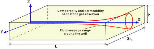
FIGURE 1. Physical model of seepage flow in low porosity and permeability sandstone horizontal gas well.
To cater to research requirements, the following assumptions are made for the seepage model of horizontal wells in low porosity and permeability sandstone gas reservoirs:
(1) The horizontal well is positioned within a closed top and bottom low porosity and permeability sandstone formation, containing a rectangular gas reservoir that exhibits heterogeneity with a supply boundary in the horizontal plane. The reservoir has a thickness of
(2) Before the development of the low porosity and permeability sandstone gas reservoir, the formation pressure was homogenous, with an original formation pressure of
(3) The horizontal well is produced with a constant bottom hole flowing pressure while assuming that the wellbore is infinitely conductive.
(4) The low porosity and permeability sandstone gas reservoir is a single-phase seepage of gas. Considering the influence of skin effect, the influence of gravity and capillary pressure is ignored.
2.1 Pollution skin factor model
Due to the varying soaking time of drilling and completion fluids in different reservoir sections along the horizontal wellbore, the depth of the contaminated zone continuously changes from the toe to the heel of the wellbore (as depicted in Figure 2A). Additionally, due to the impact of reservoir anisotropy, the pollution zone takes on an elliptical shape at any given position in the horizontal well section (as shown in Figure 2B). Therefore, this paper utilizes the seepage differential equation method to construct the pollution skin coefficient of the reservoir for horizontal wells.
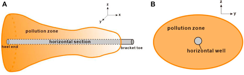
FIGURE 2. Physical model of pollution zone around the horizontal well.
2.1.1 Micro-element segment pollution skin coefficient
Due to the non-uniform distribution of pollution levels across different sections of the horizontal well, it is not possible to directly determine the skin factor of the pollution zone. Consequently, the pollution zone needs to be divided into
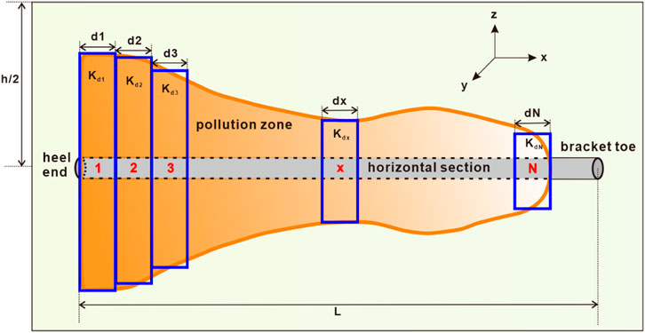
FIGURE 3. Micro-segment division diagram of pollution zone in horizontal well section.
A micro-element pollution zone of length is selected at any position of the horizontal well, as shown in Figure 4. To derive the micro-segment pollution skin factor along the horizontal well position
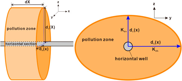
FIGURE 4. The micro-element pollution section with thickness of dx at any position x.
The plane radial flow differential equation of the
The inner boundary is a circular shaft wall, and the outer boundary is an elliptical pollution boundary. The boundary conditions are as follows:
If the flow rate in the gas layer
Where:
Considering the complexity involved in solving the aforementioned equation, we propose a similar flow substitution method to address this issue, based on the work (Furui et al., 2003b). Specifically, the potential flow problem of a point source in an elliptical seepage region is equivalent to its flow problem between two parallel straight lines with equal pressure boundaries, as illustrated in Figure 5.
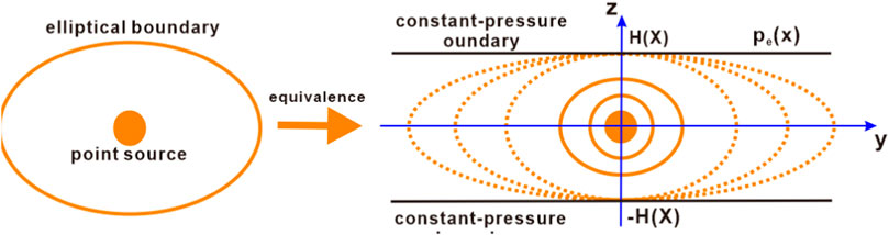
FIGURE 5. Similar flow substitution method.
The seepage problem shown in Formula 1–Formula 3 is similar to it. It only changes from the seepage problem of a point source in the elliptical seepage area to the seepage problem of a point sink. Therefore, a similar flow substitution method can also be used to solve this seepage problem. The seepage differential equation and boundary conditions corresponding to Formula 1–Formula 3 are transformed as follows:
Where:
Using the superposition principle of potential, the analytical solution of Eq. 4 can be obtained:
Formula 4 represents the distribution of pseudo-pressure around a point sink in the elliptical seepage area. Since point
At the same time, according to the trigonometric function angle Formula 8:
Formula 7 can be transformed into:
Combining Formula 6, 9, we get:
Because the analytical solution of the unknown quantity
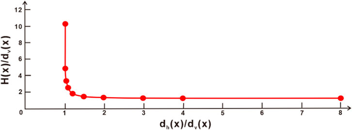
FIGURE 6. The relation curve between H (x)/dv (x) and dh (x)/dv (x).
As can be seen from Figure 6, when the variable
Since the isobaric line near the wellbore is circular, any point
Where:
At the same time, the seepage problem in the micro-segment pollution is regarded as the seepage problem of a vertical well with a gas layer thickness of
Where:
Comparing Formula 12, 13, the pollution skin coefficient in the micro-element section of a horizontal gas well is (as shown in Formula 14):
Considering that the anisotropy of the reservoir before and after pollution does not change, that is
2.1.2 Total pollution skin factor
The internal seepage field where the micro-element pollution zone is located, the productivity formula considering the skin effect can be written as Formula 16:
Where:
The productivity of the whole horizontal gas well is obtained by integration:
Where:
In general, the vertical well productivity formula considering the influence of skin factors is:
Where:
Combined with the Formula 17, 18, the calculation formula of the skin factor of the horizontal gas well pollution zone can be obtained as follows:
Considering the influence of reservoir anisotropy, the skin factor of the contaminated zone can be corrected as:
Where: Reservoir anisotropy coefficient
2.2 Pollution radius distribution model
It can be seen from Formula 15, 20 that to obtain the final pollution skin factor value, it is necessary to know the variation law of the radius of the pollution zone along the horizontal wellbore direction. Under the condition of considering the non-uniform pollution of the reservoir near the horizontal well wellbore, the skin coefficient of the horizontal well pollution zone is studied in depth (Frick and Economides, 1993; Furui et al., 2003b). It is considered that the heel end and toe end of the horizontal well wellbore are the limited positions of the contact time between the reservoir and the drilling and completion fluid. However, they assumed that the shape of the pollution zone near the wellbore is a conical prism, that is, the radius of the pollution zone varies linearly from the heel end to the well end along the horizontal wellbore.
In this paper, when studying the distribution law of pollution radius, various forms of radius distribution of pollution zone are considered (as shown in Figure 7), and the empirical equation and oscillation decreasing function of wellbore pollution radius are combined.
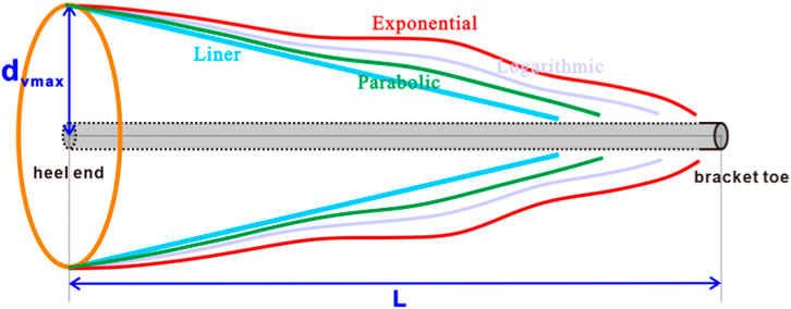
FIGURE 7. Different distribution models of horizontal gas well pollution zone.
2.2.1 Empirical equation model
Ling et al. (2015); Fan et al. (2017); Zhang (2017) and others obtained the model of drilling fluid invasion depth in horizontal wells by multiple regression processing of experimental data. Based on the research (Jiang et al., 2023), the distribution law of the radius of the contaminated zone along the vertical direction of the wellbore is given as follows:
Where:
2.2.2 Oscillating decline function model
Combined with the research (Jiang et al., 2023), the oscillating decline function is introduced to represent the distribution model of the vertical radius of the wellbore pollution zone (as shown in Formula 22):
Where:
The empirical model (Formula 23) for calculating the maximum invasion depth of drilling fluid in horizontal wells was obtained by multiple regression of experimental data (Fan et al., 2017):
Where:
Among them: the oscillation function expression is:
In Formula 24,
In anisotropic reservoirs, the expression of the decreasing function
The equation coefficient in Formula 25 is related to the length of the well section and is greater than 0. It can be seen that the above Formula 19 belongs to the parabolic decreasing function. Therefore, combining Formula 21, 24, an oscillating decline function model can be obtained, which is the distribution of pollution zones around horizontal wells.
So far, the pollution skin coefficient model of horizontal gas wells in low porosity and permeability sandstone has been constructed, as shown in Formula 26. The degree of reservoir damage can be judged according to the pollution skin coefficient, and the appropriate acidification radius can be selected according to the pollution radius, to optimize and design the stimulation measures of horizontal gas wells.
3 Model validation
Through literature research, it is found that the productivity formula of horizontal wells in gas reservoirs (Borisov, 1964; Giger et al., 1984; Joshi, 1986; Renard and Dupuy, 1991; Furui et al., 2003a), only the Furui formula considers both skin effect and reservoir anisotropy. Therefore, we compare the model and Furui model with the actual production capacity. The basic data of the actual gas well J (as shown in Table 1) are substituted into this model, and the Furui model to calculate the productivity of horizontal gas wells, yielding the calculation results depicted in Table 2.
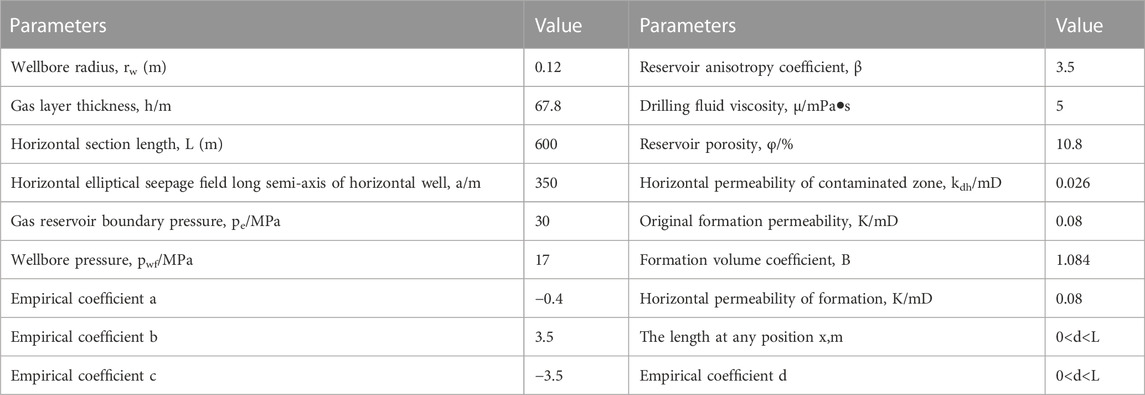
TABLE 1. Basic data of well H.
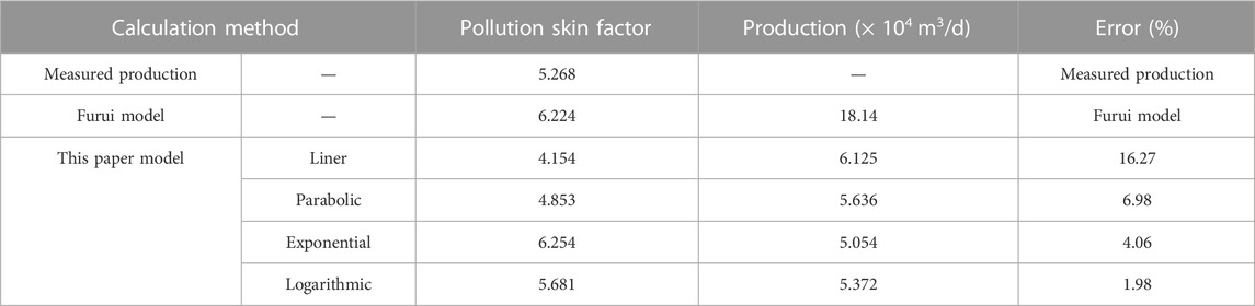
TABLE 2. Comparison table of three model calculation results and actual productivity results.
By examining Table 2, we observe that among the different pollution radius decreasing functions computed in this study, the skin coefficient values of parabolic, exponential, and logarithmic distributions and productivity values closely align with the measured values. Furthermore, the productivity error remains below 10%, highlighting the accuracy of our model in estimating productivity. Notably, the logarithmic distribution of pollution radius results in the smallest productivity error, with a mere 1.98%. The linear distribution, on the other hand, yields a productivity value of approximately 16% in comparison to the measured value, indicating a slightly larger error rate. By utilizing the Furui model, the logarithmic distribution model, and the measured data, we can generate the pressure difference-capacity change diagram displayed in Figure 8.
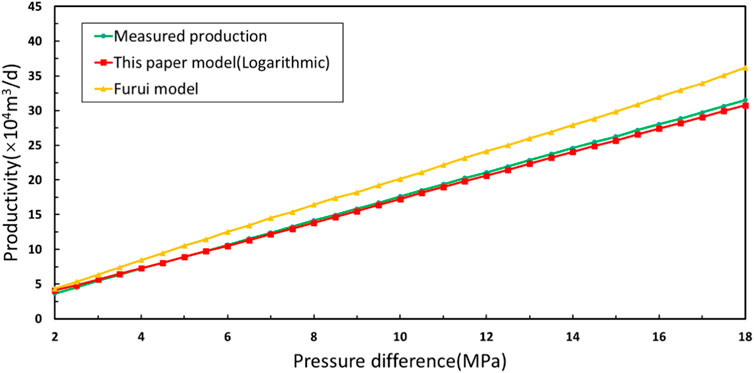
FIGURE 8. Pressure difference-capacity change curves based on three different calculation methods.
Upon analyzing the pressure difference and productivity change curve depicted in Figure 8, the calculation results of the model in this paper are in good agreement with the actual productivity value, and the error is very small. Conversely, there exists a noticeable disparity between the curve distribution of the Furui model and the actual data, resulting in a substantial error. Table 3 presents the corresponding productivity values and error values relative to the actual productivity for the two models at pressure difference levels of 6, 12, and 18 MPa.
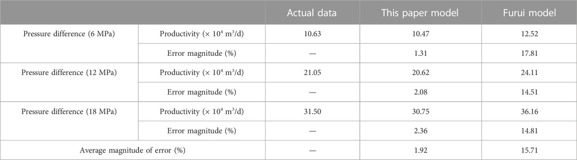
TABLE 3. Productivity value and error value of two models under different pressure differences.
Based on the data analysis in Table 3, it is evident that the Furui model exhibits an average error of 15.71%. While the model considers the anisotropic characteristics of the reservoir and the factors influencing the skin layer during construction, it assumes a simple linear distribution for the radius of the pollution zone. This assumption overlooks the existence of complex pollution zone distributions in actual formation conditions. Consequently, this linear assumption can result in significant prediction errors, limiting the model’s applicability, especially in reservoirs with nonlinear pollution zone distributions.
On the other hand, the model proposed in this study exhibits a significantly lower relative error of only 1.92%, compared to the Furui model. This outstanding performance highlights the significance of accounting for reservoir anisotropy and the necessity of considering various types of pollution zone radius distributions, such as linear, parabolic, exponential, logarithmic, and other potential trends. The accurate and low-error calculation results of this model validate its scientific, rational, and practical nature, indicating its ability to more precisely reflect actual formation conditions and reservoir characteristics.
This model’s close alignment with and accurate calculation of real-world productivity data proves its suitability for evaluating the productivity of horizontal gas wells. As a valuable tool, it offers robust technical support for predicting productivity, making informed decisions on stimulation measures, and optimizing production schemes. Ultimately, it enhances development efficiency and maximizes economic returns in oil and gas fields.
4 Sensitivity analysis
Based on the Formula 24 mentioned above, the skin factor of the pollution zone is calculated for a specific length of horizontal gas wells. The impact of factors such as the maximum vertical depth of the pollution zone, permeability, and reservoir anisotropy on both the micro-segment skin factor and the overall skin factor of the pollution zone is discussed and analyzed. To illustrate this, we consider a low-permeability sandstone horizontal gas well, specifically the Z well in the A oilfield, and calculate the fundamental data for this well (as presented in Table 4). Figures 9–12 depicts the variation curve of the pollution skin coefficient under the influence of different parameters.
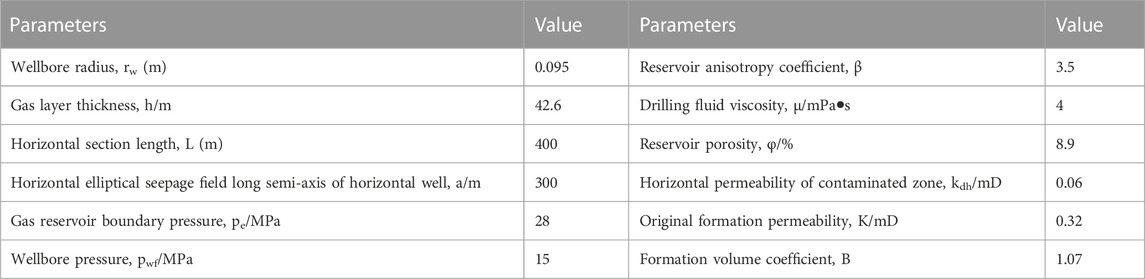
TABLE 4. Basic data of Z well in A oilfield.
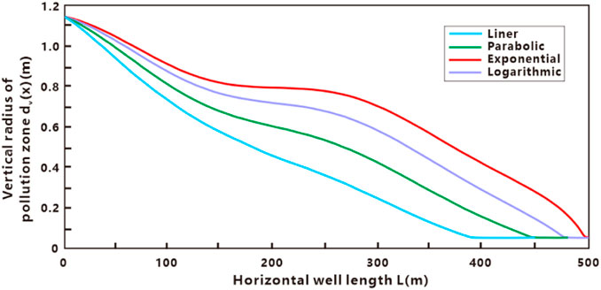
FIGURE 9. The variation curve of dv (x) with L under four decreasing modes.

FIGURE 10. The variation curve of S (x) with L under four decreasing modes.
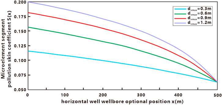
FIGURE 11. The effect of dvmax on S (x).
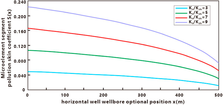
FIGURE 12. The effect of Kdh on S (x).
From Figure 9, it is apparent that the vertical maximum radius of the contaminated zone is 1.15 m, while the minimum radius is almost equal to the wellbore radius. Comparing the different distribution modes, we observe that the radius of the exponential decreasing distribution exhibits the highest pollution level, while the radius of the liner decreasing distribution exhibits the lowest level of pollution. It is noticeable that when the horizontal well length does not exceed 100 m, the difference in the pollution radius under different decline modes is not significant, indicating that the area closest to the heel of the horizontal well is the most heavily polluted, with the pollution radius being extremely substantial. We can observe from Figure 10 that the pollution skin coefficient in the micro-element section gradually decreases from the heel end to the toe end of the horizontal well. This trend is because the contact time between the formation and the drilling and completion fluid is the longest at the heel end of the horizontal well, leading to the most severe pollution of the nearby formation. Conversely, the shortest contact time occurs at the toe end, resulting in the smallest pollution radius and lowest pollution skin coefficient. Figures 9, 10 also show that the exponential distribution of the pollution radius has the most significant impact on the pollution skin coefficient along the heel-to-toe length of the horizontal well, while the linear distribution has the least influence on the pollution skin coefficient.
Figure 11 displays a curve depicting the gradual decrease in pollution skin coefficient along the micro-element section of the horizontal well, from the heel end to the toe end, for different maximum vertical radii of the pollution zone (0.3 m, 0.6 m, 0.9 m, and 1.2 m). As per the graph, the pollution skin factor gradually decreases with the increase in the vertical radius of pollution, indicating a gradual reduction in the pollution degree of drilling fluid to the reservoir far from the wellbore in the same micro-segment. As the maximum pollution radius approaches the heel end of the horizontal well, it significantly impacts the skin factor of the micro-segment. However, in the vicinity of the toe end of the horizontal well, the radius of the contaminated zone does not affect the distribution of the skin factor in the micro-element section. This implies that the contact time between the drilling and completion fluid and the reservoir around the wellbore is brief at the toe end, resulting in weak formation pollution.
Figures 12, 13 provide insights into the impact of pollution permeability on the skin factor of the micro-segment and the total pollution skin factor, as well as the influence of the maximum pollution radius on the total pollution skin factor. By examining Figure 12, it is evident that the skin factor gradually decreases along the micro-element section of the horizontal well, from the heel end to the toe end. Additionally, it is observed that the micro-element section’s skin factor increases with a decrease in the permeability of the pollution zone, resulting in a higher total skin factor for the pollution zone. Therefore, when dealing with reservoirs experiencing severe pollution, it is advisable to consider measures such as acidizing and other remedial techniques to improve the permeability of the contaminated zone. This in turn would help reduce the overall skin factor. By observing Figure 12, it becomes evident that the skin factor of the micro-segment pollution gradually reaches an equilibrium value along the horizontal well as any position analyzes it. This indicates that pollution from drilling and completion fluids decreases along the heel-to-toe axis of the well, with the formation’s pollution permeability also decreasing gradually. Based on the insights provided in Figure 13, it can be deduced that the total skin factor gradually decreases with an increase in the permeability of the contaminated zone. When the contaminated zone’s permeability matches that of the reservoir, the total skin factor becomes zero, indicating an uncontaminated reservoir. Additionally, as the maximum pollution radius expands, the overall skin factor of the pollution increases gradually. However, it is worth noting that the influence of the maximum pollution radius on the total skin factor is relatively minor compared to its impact on the micro-segment skin factor.
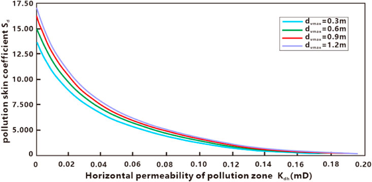
FIGURE 13. The effect of dvmax on Sd.
In the sensitivity analysis of comprehensive influencing factors, it is observed that both the pollution radius and pollution permeability decrease gradually from the heel to the toe of the horizontal well. Among the various distributions, the exponential distribution of the pollution radius exhibits the most significant impact on the pollution skin coefficient, while the linear distribution has the least influence. Furthermore, as the pollution zone radius expands and the pollution permeability decreases, the skin factor of the micro-segment and the total pollution skin factor increase accordingly.
5 Summary and conclusion
In this paper, we develop a piecewise superposition model to describe the pollution zone’s skin factor. The model combines the differential method and the similar flow substitution method, while the wellbore pollution zone’s vertical distribution is described by an oscillation-decreasing function. We propose a method to evaluate the degree of formation pollution for accurate characterization of pollution status. The main findings are as follows:
(1) The model’s skin factor and productivity values closely align with measured values, with errors less than 10% for parabolic, exponential, and logarithmic pollution radius decreasing functions. The logarithmic distribution has the smallest productivity error at 1.98%. In contrast, the linear distribution shows a larger deviation of approximately 16% between the estimated and measured yield.
(2) Considering reservoir anisotropy and the radius distribution of different pollution zones, the model in this paper demonstrates an average error of only 1.92%. This highlights its rationality and practicality. The model can guide stimulation strategy optimization, prevent and reduce formation damage, and contribute to economic benefits in oilfield development.
(3) The sensitivity analysis illustrates that from the heel to the toe of the horizontal well, both the pollution radius and pollution permeability progressively decrease. Of all, the exponential distribution of the pollution radius exerts the most significant influence on the pollution skin coefficient. An increase in the pollution radius coupled with a decrease in the pollution permeability escalates both the skin factor and overall pollution skin factor of the horizontal well.
Data availability statement
The original contributions presented in the study are included in the article/Supplementary material, further inquiries can be directed to the corresponding author.
Ethics statement
The manuscript presents research on animals that do not require ethical approval for their study.
Author contributions
SZ: Conceptualization, Investigation, Methodology, Validation, Writing–original draft, Writing–review and editing. KG: Methodology, Writing–review and editing. ZZ: Formal Analysis, Writing–review and editing. All authors contributed to the article and approved the submitted version.
Funding
The author(s) declare that no financial support was received for the research, authorship, and/or publication of this article.
Acknowledgments
The authors are very grateful for the support of Yangtze University for this article. The authors wish to acknowledge KG for interpreting the significance of the results of this study.
Conflict of interest
The authors declare that the research was conducted in the absence of any commercial or financial relationships that could be construed as a potential conflict of interest.
Publisher’s note
All claims expressed in this article are solely those of the authors and do not necessarily represent those of their affiliated organizations, or those of the publisher, the editors and the reviewers. Any product that may be evaluated in this article, or claim that may be made by its manufacturer, is not guaranteed or endorsed by the publisher.
References
Bahrami, H., Rezaee, R., Ostojic, J., Nazhat, D., and Clennell, B. (2011). Evaluation of damage mechanisms and skin factor in tight gas reservoirs. In (OnePetro). doi:10.2118/142284-MS
Basquet, R., Alabert, F. G., Caltagirone, J. P., and Batsale, J. C. (1998). A semi-analytical approach for productivity evaluation of wells with complex geometry in multilayered reservoirs. In (OnePetro). doi:10.2118/49232-MS
Borisov, J. P. (1964). Oil production using horizontal and multiple deviation wells. Moscow: Nedra, 32–36.
Chu, H., Ma, T., Zhu, W., Gao, Y., Zhang, J., and John Lee, W. (2023). A novel semi-analytical monitoring model for multi-horizontal well system in large-scale underground natural gas storage: Methodology and case study. Fuel 334, 126807. doi:10.1016/j.fuel.2022.126807
Fan, Y., Wu, J., Wu, F., Zhou, C., and Li, C. (2017). A new physical simulation system of drilling mud invasion in formation module. Petroleum Explor. Dev. 44, 127–131. doi:10.1016/S1876-3804(17)30016-2
Furui, K., Zhu, D., and Hill, A. D. (2003a). A rigorous formation damage skin factor and reservoir inflow model for a horizontal well.
Furui, K., Zhu, D., and Hill, A. D. (2003b). A rigorous formation damage skin factor and reservoir inflow model for a horizontal well. SPE Prod. Facil. 18, 151–157. doi:10.2118/84964-PA
Giger, F. M., Reiss, L. H., and Jourdan, A. P. (1984). The reservoir engineering aspects of horizontal drilling.
Huang, B., Xiao, X., and Li, X. (2003). Geochemistry and origins of natural gases in the Yinggehai and Qiongdongnan basins, offshore South China Sea. Org. Geochem. 34, 1009–1025. doi:10.1016/S0146-6380(03)00036-6
Jia, A., Wei, Y., Guo, Z., Wang, G., Meng, D., and Huang, S. (2022). Development status and prospect of tight sandstone gas in China. Nat. Gas. Ind. B 9, 467–476. doi:10.1016/j.ngib.2022.10.001
Jianchun, G., Cong, L., Yong, X., Jichuan, R., Chaoyi, S., and Yu, S. (2014). Reservoir stimulation techniques to minimize skin factor of Longwangmiao Fm gas reservoirs in the Sichuan Basin. Nat. Gas. Ind. B 1, 83–88. doi:10.1016/j.ngib.2014.10.011
Jiang, G.-C., Li, Y.-Z., He, Y.-B., Dong, T.-F., Sheng, K.-M., and Sun, Z. (2023). Subsection and superposition method for reservoir formation damage evaluation of complex-structure wells. Petroleum Sci. 20, 1843–1856. doi:10.1016/j.petsci.2023.01.010
Karakas, M., and Tarlq, S. M. (1991). Semianalytical productivity models for perforated completions. SPE Prod. Eng. 6, 73–82. doi:10.2118/18247-PA
Klemetsdal, Ø. S., Berge, R. L., Lie, K.-A., Nilsen, H. M., and Møyner, O. (2017). Unstructured gridding and consistent discretizations for reservoirs with faults and complex wells. In (OnePetro). doi:10.2118/182666-MS
Li, J., and Wang, T. (2022). Production analysis of horizontal wells in a two-region composite reservoir considering formation damage. Front. Energy Res. 10, 818284. doi:10.3389/fenrg.2022.818284
Ling, K., Zhang, H., Shen, Z., Ghalambor, A., Han, G., He, J., et al. (2015). A new approach to estimate invasion radius of water-based-drilling-fluid filtrate to evaluate formation damage caused by overbalanced drilling. SPE Drill. Complet. 30, 27–37. doi:10.2118/168184-PA
Longeron, D., Argillier, J.-F., and Audibert, A. (1995). An integrated experimental approach for evaluating formation damage due to drilling and completion fluids. In (OnePetro). doi:10.2118/30089-MS
McLeod, H. O. (1983). The effect of perforating conditions on well performance. J. Petroleum Technol. 35, 31–39. doi:10.2118/10649-PA
Meakin, P., Huang, H., Malthe-Sørenssen, A., and ThØgersen, K. (2013). Shale gas: opportunities and challenges. Environ. Geosci. 20, 151–164. doi:10.1306/eg.05311313005
Moore, T. A. (2012). Coalbed methane: a review. Int. J. Coal Geol. 101, 36–81. doi:10.1016/j.coal.2012.05.011
Moreno, J. C., Bradley, D., Gurpinar, O., Richter, P., Hussain, A., Shammari, M., et al. (2006). Optimized workflow for designing complex wells. In (OnePetro). doi:10.2118/99999-MS
Patel, M. C., and Singh, A. (2016). Near wellbore damage and types of skin depending on mechanism of damage. In (OnePetro). doi:10.2118/179011-MS
Renard, G., and Dupuy, J. M. (1991). Formation damage effects on horizontal-well flow efficiency (includes associated papers 23526 and 23833 and 23839). J. Petroleum Technol. 43, 786–869. doi:10.2118/19414-PA
Sau, R., Goodrow, A., Rockwell, M., Mayer, C. S. J., Shuchart, C. E., and Grubert, M. A. (2014). An integrated software technology based on research and field application for completion, stimulation and fluid placement design in complex wells. In (OnePetro). doi:10.2523/IPTC-17870-MS
Sun, E., Yang, W., Peng, Q., Meng, P., and Mu, S. (2019). The productivity model of horizontal well considering acidification effect in anisotropic reservoirs. World J. Eng. Technol. 08, 19–32. doi:10.4236/wjet.2020.81003
Tang, H., Sun, Z., He, Y., Chai, Z., Hasan, A. R., and Killough, J. (2019). Investigating the pressure characteristics and production performance of liquid-loaded horizontal wells in unconventional gas reservoirs. J. Petroleum Sci. Eng. 176, 456–465. doi:10.1016/j.petrol.2019.01.072
Thomas, L. K., Todd, B. J., Evans, C. E., and Pierson, R. G. (1998). Horizontal well IPR calculations. SPE Reserv. Eval. Eng. 1, 392–399. doi:10.2118/51396-PA
Van, J., Jiang, G., and Wu, X. (1997). Evaluation of formation damage caused by drilling and completion fluids in horizontal wells. J. Can. Petroleum Technol. 36. doi:10.2118/97-05-02
Wang, Z., Sun, Z., Zhang, D., Zhu, J., Li, X., Huang, B., et al. (2015a). Geology and hydrocarbon accumulations in the deepwater of the northwestern South China Sea—with focus on natural gas. Acta Oceanol. Sin. 34, 57–70. doi:10.1007/s13131-015-0715-7
Wang, Z., Sun, Z., Zhu, J., Guo, M., and Jiang, R. (2015b). Natural gas geological characteristics and great discovery of large gas fields in deep-water area of the western South China Sea. Nat. Gas. Ind. B 2, 489–498. doi:10.1016/j.ngib.2016.03.001
Xiao, D., Hu, Y., Wang, Y., Deng, H., Zhang, J., Tang, B., et al. (2022). Wellbore cooling and heat energy utilization method for deep shale gas horizontal well drilling. Appl. Therm. Eng. 213, 118684. doi:10.1016/j.applthermaleng.2022.118684
Yildiz, T. (2006). Assessment of total skin factor in perforated wells. SPE Reserv. Eval. Eng. 9, 61–76. doi:10.2118/82249-PA
Zhang, G., Wang, D., Lan, L., Liu, S., Su, L., Wang, L., et al. (2021a). The geological characteristics of the large- and medium-sized gas fields in the South China Sea, 40.
Zhang, J. (2017). Effects of porosity and permeability on invasion depth during drilling mud-filtrate invading into a reservoir dynamically. Atlantis Press, 203–206. doi:10.2991/emim-17.2017.44
Zhang, S., Guo, K., Yang, H., and Gao, X. (2023). The productivity segmented calculation model of perforated horizontal wells considering whether to penetrate the contaminated zone. Front. Earth Sci. 11. doi:10.3389/feart.2023.1270662
Zhang, Z., Guo, J., Liang, H., and Liu, Y. (2021b). Numerical simulation of skin factors for perforated wells with crushed zone and drilling-fluid damage in tight gas reservoirs. J. Nat. Gas Sci. Eng. 90, 103907. doi:10.1016/j.jngse.2021.103907
Keywords: low porosity and permeability sandstone, horizontal well, reservoir damage evaluation, skin factor, pollution radius, segmented superposition model
Citation: Zhang S, Guo K and Zhang Z (2023) Segmented superimposed model of near-bore reservoir pollution skin factor for low porosity and permeability sandstone horizontal gas wells. Front. Earth Sci. 11:1335629. doi: 10.3389/feart.2023.1335629
Received: 14 November 2023; Accepted: 05 December 2023;
Published: 29 December 2023.
Edited by:
Tianshou Ma, Southwest Petroleum University, ChinaReviewed by:
Nian Peng, Chongqing University of Science and Technology, ChinaSen Wang, China University of Petroleum, China
Copyright © 2023 Zhang, Guo and Zhang. This is an open-access article distributed under the terms of the Creative Commons Attribution License (CC BY). The use, distribution or reproduction in other forums is permitted, provided the original author(s) and the copyright owner(s) are credited and that the original publication in this journal is cited, in accordance with accepted academic practice. No use, distribution or reproduction is permitted which does not comply with these terms.
*Correspondence: Shuangshuang Zhang, d2Fpd2FpMTUxNUAxNjMuY29t