 Yingwei Wang1,2
 Man Wang
 Rui Min
 Jingwei Zheng
- 1Pingdingshan Tianan Coal Mining Co., Ltd., Pingdingshan, China
- 2State Key Laboratory of Coking Coal Exploitation and Comprehensive Utilization, Pingdingshan, China
- 3State Key Laboratory of Coal Mine Disaster Dynamics and Control, Chongqing University, Chongqing, China
Accurately predicting fracture initiation pressure is crucial for successfully applying hydraulic fracturing technology in layered reservoirs. However, existing models overlook the effects of rock anisotropy and borehole deformation. In this study, we simplified the layered reservoir to a transversely isotropic medium and developed a model to estimate borehole deformation precisely. Based on this estimated deformation, we created a model to predict fracture initiation pressure in hydraulic fracturing. By comparing previous models and experimental data, we validated the effectiveness of these proposed models. We examined the impacts of various factors on borehole deformation, fracture initiation pressure, and initiation angle. The results revealed that circular boreholes in layered reservoirs deform into elliptical boreholes under in situ stress, with the major axis not aligning with the principal stress direction, which highlights the significant impact of rock anisotropy on borehole deformation. Furthermore, the fracture initiation pressure of hydraulic fracturing either increases or decreases following borehole deformation, depending on specific geological parameters. The calculated initiation angle after borehole deformation is within 10°, closer to previous experimental results, underscoring the notable effect of borehole deformation on hydraulic fracturing. Our research indicates that the impact of borehole deformation on hydraulic fracturing is significant and should not be overlooked. This finding will offer fresh avenues for further study in the field of hydraulic fracturing.
1 Introduction
Hydraulic fracturing technology is extensively utilized in layered reservoirs such as shale, tight sandstone, and coal (Abdulelah et al., 2018; Qu et al., 2022a; Lu et al., 2022). This method efficiently enhances reservoir permeability by creating artificial fractures, thereby significantly boosting the extraction of unconventional natural gas (Song et al., 2017; Zhao et al., 2020a; He et al., 2022a; He et al., 2022b; Li et al., 2022; Zhao et al., 2022; Liu et al., 2023). Accurately predicting and minimizing the fracture initiation pressure (FIP) near boreholes in rocks and comprehending fracture extension behavior is crucial (Wu et al., 2020; Huang et al., 2023a). The analysis of FIP through a mechanistic-based theoretical approach is widely acknowledged as an effective method (Shou and Zhou, 2021; Ren et al., 2022) and has been extensively researched by numerous scholars.
Hubbert and Willis. (1957) were the pioneers who proposed a theory to predict FIP. Subsequently, numerous scholars contributed significantly to the development of related theories (Eaton, 1969; Constant and Jr, 1988; Detournay and Cheng, 1988; Oriji and Ogbonna, 2012; Ma et al., 2017; Zhang et al., 2018.). While the accuracy of predicted values has improved over time and can generally meet basic engineering requirements, there are instances where a discrepancy exists between predicted and actual values (Ma et al., 2019). This discrepancy can be attributed to these models’ assumption of uniform mechanical properties in all directions. At the same time, shale, tight sandstone, and coal exhibit significant anisotropic characteristics with varying mechanical properties on parallel and perpendicular bedding planes. As a result, these reservoirs typically be simplified as transverse isotropic mediums (Espinoza et al., 2013; Li and Zhang, 2019; Ma et al., 2021). Existing laboratory experiments on fracturing have shown that the FIP of hydraulic fracturing varies as the angle between the bedding plane and the borehole changes, highlighting the significant impact of rock anisotropy, a factor acknowledged by numerous scholars (Qu et al., 2022a; Liu et al., 2022; Zhang et al., 2023). Numerous researchers have conducted theoretical examinations on the influence of rock anisotropy. Aadnoy and Chenvert. (1987) were the first to propose a stability model for boreholes using anisotropic body theory. Since then, numerous researchers have adopted similar approaches to investigate the FIP for boreholes in transversely isotropic formation (Ong and Roegiers, 1995; Gupta and Zaman, 1999; Prioul et al., 2011; Zhu et al., 2014.). Do et al. (2017) developed a model incorporating hydraulic and mechanical anisotropy to predict the FIP of boreholes with permeable and impermeable boundaries. Sesetti and Ghassemi. (2018) also developed a model that considers elasticity and fracture anisotropy to predict FIP for boreholes in transversely isotropic formations. Ma et al. (2022) developed a model that considers the anisotropy of rock strength to predict FIP for both vertical and inclined boreholes. In addition, the heterogeneity of the reservoir influences the propagation of fractures (Wu et al., 2023), resulting in the creation of intricate fractures (Zhou et al., 2020; Huang et al., 2023b), which also significantly impact the extraction of reservoir gas (Zhao and Zhou, 2020b; Song et al., 2020). Therefore, it is crucial to consider the effect of reservoir anisotropy on the efficiency of hydraulic fracturing.
Several scholars have developed models to predict FIP for transversely isotropic reservoirs in hydraulic fracturing. However, these models are specifically designed for the circular borehole. Field logging data shows that circular boreholes can deform due to stress and mechanical anisotropy (Figure 1) (Zoback et al., 2003; Pierdominici et al., 2020; Han et al., 2021). Various studies have investigated the effects of borehole deformation. For instance, Haimson and Lee. (2004) discovered that circular boreholes in sandstone deform significantly and assume an elliptical shape under uneven loading. Zhai et al. (2015) observed that a circular borehole in an on-site coal seam became elliptical after redistributing in situ stresses. Gao and Ren. (2022) found that circular boreholes deform into elliptical boreholes due to stress exertion in hydraulic fracturing. Several researchers have studied the stress distribution around elliptical boreholes and concluded that changes in borehole shape affect the distribution of the stress field, which in turn affects the destructive behavior of the rock (Qi et al., 2018; Chen et al., 2020; Zhong et al., 2021). Scholars have established models based on theoretical mechanics to compute the deformation of circular boreholes and estimate their precise dimensions (Zou et al., 2018; Fang et al., 2022; Han et al., 2023). However, these models primarily consider the impact of stress anisotropy while disregarding the influence of mechanical anisotropy. Consequently, these models are not suitable for anisotropic formations. Moreover, current fracturing models have failed to establish a correlation between borehole deformation and FIP.
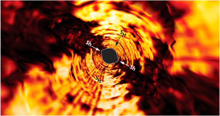
FIGURE 1. Three-dimensional borehole breakout view from ABI image of the PTA2 borehole wall. Sh and SH are the orientations of the minimum and maximum horizontal principal stresses, respectively (Pierdominici et al., 2020).
In this study, we developed a model to estimate borehole deformation in the layered reservoir. Subsequently, we formulated a mechanical model to predict the FIP in hydraulic fracturing, considering the shape and magnitude of the estimated borehole deformation. Our proposed model was verified by comparing them with previous models. Moreover, we conducted a thorough analysis to evaluate the influence of different factors on the extent of borehole deformation, FIP, and initiation angle.
2 FIP model after borehole deformation
2.1 Analysis of circular borehole deformation
This study defines compressive stress as positive and tensile stress as negative stress. The layered reservoir is assumed to be a homogeneous, continuous, linear transverse isotropic medium that undergoes small deformations. Due to the length of the boreholes being significantly more significant than their diameter, the generalized plan strain condition is applicable. In addition, this study ignores the effects of temperature, chemical environment, and seepage.
Assuming the bedding plane exhibits symmetry along the z-axis (Figure 2A), only stresses in the x1oy1 plane impact the borehole deformation and FIP, which allows for simplifying the analysis to a planar problem (Heng et al., 2021) (Figure 2B). In Figure 2B, we established the in situ stress coordinate system (x1oy1) is established along the direction of the in situ stress. The x1 and y1 axes align with the direction of the in situ stresses σH and σh, respectively. Additionally, we defined a bedding plane coordinate system (x2oy2) along the direction of the bedding plane. The x2 and y2 axes are parallel and perpendicular to the bedding plane (Figure 2C). We denoted the angle between the x1 and x2 axes as α. By employing the coordinate transformation formula (1), we can obtain the stress components in the bedding plane coordinate system.
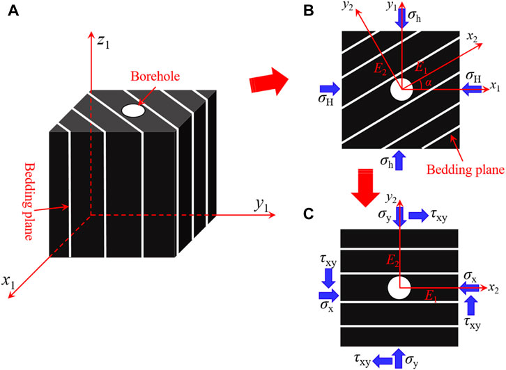
FIGURE 2. (A) A vertical borehole in the layered reservoir. (B) The stress distribution around the vertical borehole, with the bedding plane at an angle α to the axis of the maximum principle stress axis. (C). The equivalent stress around the borehole after a rotation of angle α.
Where σh and σH are the minimum and maximum horizontal principal stresses, respectively, MPa; α is the inclination angle of the bedding plane, °.
The borehole deformation under generalized plane strain conditions is illustrated below (Please refer to Appendix A for detailed derivation):
Where u and v are the displacement in the directions of x1 and y1 axes, m.
The new coordinates points of the borehole wall, resulting from the borehole deformation under the influence of in situ stress, are as follows:
2.2 Determination of shape after circular borehole deformation
The coordinates points of the borehole wall after the borehole deformation in Equation 3 satisfy the following equation:
where:
Equation 4 is the general equation of the ellipse, indicating that circular boreholes in anisotropic reservoirs will deform into elliptical boreholes under the effect of the in situ stress. This observation aligns with the logging data (Zoback et al., 2003; Han et al., 2021), indicating that the proposed model is consistent with the actual situation.
The major axis (a), minor axis (b), and angle β between the major axis of the ellipse and the coordinate axis x1 can be determined using Equation 4 and relevant mathematical knowledge (β is defined as the deflection angle, the calculation procedure is provided in Appendix B).
When μ1=μ2=i, β=0, E1=E2, v12=v13, we can simplify the model to evaluate the deformation of a borehole in an isotropic stratum under positive stress; at this time, the major axis, minor axis, and deflection angle in Equation 5 are as follows:
Equation 6 is consistent with the borehole deformation model in isotropic reservoirs, as Zou et al. (2018) established, indicating the proposed model’s precision.
2.3 Stress distribution around the circular borehole after deformation
We analyzed the stress distribution around the elliptical borehole in hydraulic fracturing, considering the relevant parameters of the circular borehole after deformation, established a new coordinate system (x3oy3) (Figure 3), in which the x3 and y3 axes are parallel to the major and minor axes of the elliptical borehole, respectively. By applying the coordinate transformation formula (7), we obtained the stress components of the in situ stress in this coordinate system:
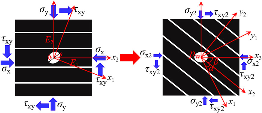
FIGURE 3. The stress distribution around the elliptical borehole.
We obtained the stress distribution around the elliptical borehole in anisotropic media using the stress analysis method for the planar orifice problem (Please refer to Appendix C for detailed derivation).
Where
Thus on the borehole wall:
We can obtain the stress distribution around an elliptical borehole in a Cartesian coordinate system by substituting Equation 10, Equation 9 into Equation 8.
2.4 Prediction model of FIP for the elliptical borehole
If the tangential stress exerted on the borehole wall exceeds the tensile strength of the reservoir, the borehole will failure. Therefore, it is essential first to assess the tangential stress of the borehole. By utilizing the coordinate transformation formula (11), we can determine tangential stress distribution at any point along the borehole wall.
Previous research indicated that anisotropic rocks have different tensile strengths in different directions (Ma et al., 2017). Furthermore, the N-E criterion can be used to accurately assess the tensile strength of anisotropic rocks in any direction as follows (Nova and Zaninetti, 1990):
Where T1 and T2 are the tensile strength perpendicular and parallel to the bedding plane, respectively, MPa.
Suppose the tangential stress exceeds the rock’s tensile strength. In that case, the rock enters the failure stage (Equation 13). At this moment, the pressure at which the fracturing fluid is injected, known as pw, represents the FIP.
Where σt is the tensile strength of the rock, MPa.
The initiation angle of the fracture can be determined using the following equation (Liang et al., 2022), where θ is the initiation angle.
3 Model validation
3.1 Model validation by different model comparisons
We have successfully validated the proposed borehole deformation model in Section 2.2. Furthermore, it is necessary to validate the proposed FIP model for the elliptical borehole in the anisotropic medium, and we can achieve it by degrading this model to an isotropic model and comparing it with existing models. The existing models that can be used for comparison are the elliptical model in the isotropic medium proposed by Aadnoy and Angell-olsen. (1995) (Eq. 15) and Ge et al. (2019) (Eq. 16), respectively. The specific forms of these models are as follows:
When calculating the tangential stress on the wall of the elliptical borehole, we utilize the following values: the borehole radius is 0.12 m, c is 1.2, m is 0.6, σx2 is 50MPa, σy2 is 30 MPa, τxy2 is 0, and the fracturing fluid injection pressure is 20 MPa. We determine the tangential stresses on the borehole wall using Aadnoy’s, Ge et al.'s, and our proposed model. We presented the results in Table 1. The table demonstrates that the proposed model yields similar results to Aadnoy’s and Ge et al.'s models when μ11=1.001i and μ22=0.999i, which indicates the accuracy of our proposed model and its applicability in studying the stress distribution around the elliptical borehole in the anisotropic medium.
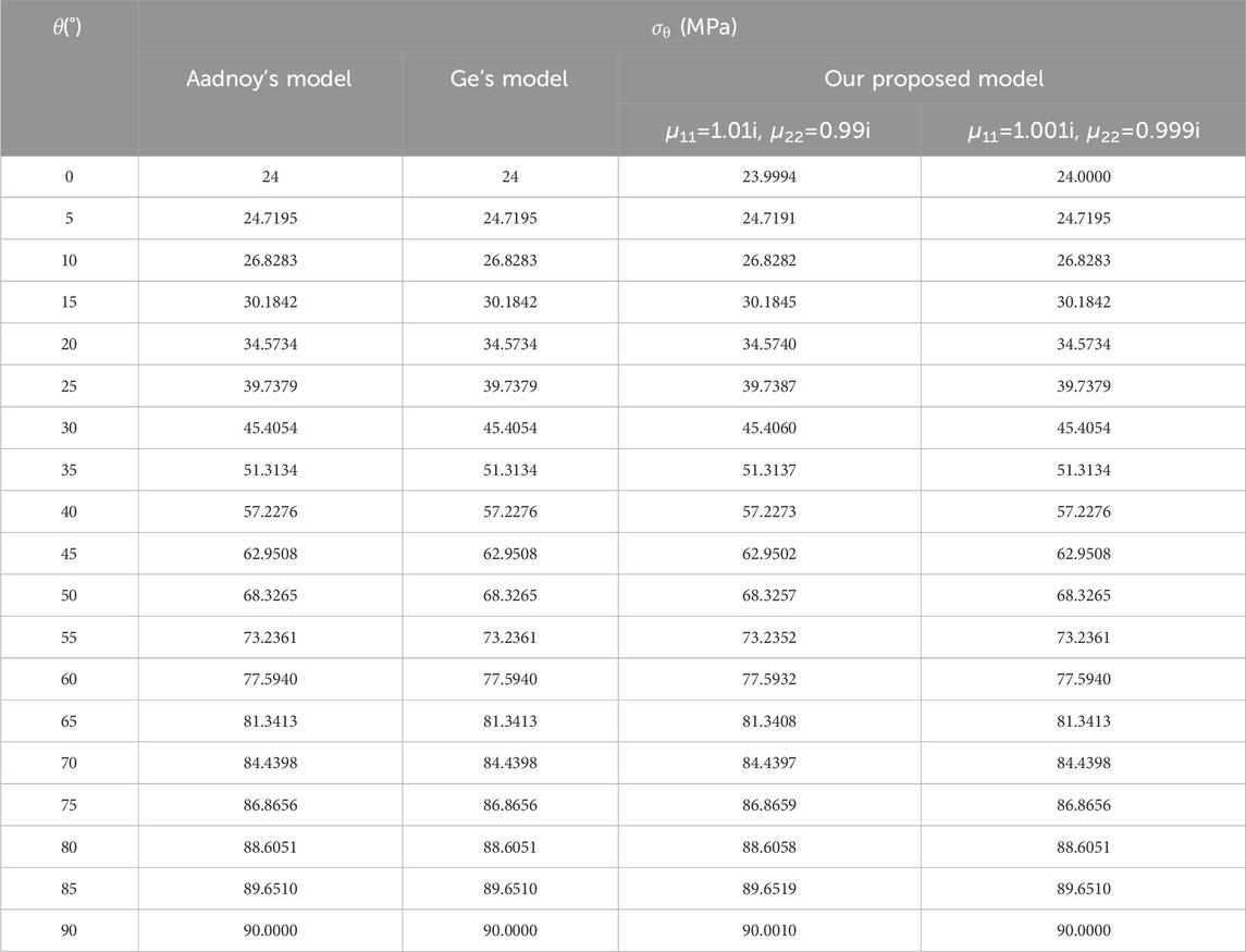
TABLE 1. Comparison of tangential stress on the wall of the elliptical borehole.
3.2 Model validation by experimental data
To validate the dependability of the proposed model, we substituted the experimental conditions and mechanical parameters from the literature (Liu et al., 2022) into our proposed model and Ma et al.'s model. (Ma et al., 2022). We presented the experiment and calculation results in Figure 4. The FIP decreases as the bedding inclination angle increases, and the calculation results align with the experimental findings. The concave shape of the curve derived from the experimental data aligns with the results of our proposed model, whereas the curve model from Ma et al. exhibits a convex shape. Additionally, our model’s calculation results closely match the experimental data, leading to a maximum 47.6% (23°) improvement in accuracy compared to Ma et al.'s model, which indicates the superiority of our model in predicting the FIP of reservoirs with a significant angle between the bedding plane and stress direction, highlighting its advanced predictive nature.
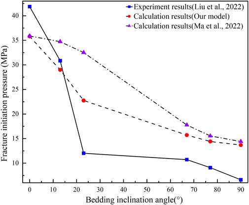
FIGURE 4. Comparison of calculated results in the present study with experimental results in the previous literature.
4 Analysis of factors impacting borehole deformation and FIP
We calculated the FIP and initiation angle of the initial circular borehole by substituting the radius (R) into Equations 13, 14 to replace the major axis (a) and minor axis (b) of the elliptical borehole, then calculated the size of the borehole deformation and the deflection angle (β) under various factors using Matlab software, and compared the FIP and the initiation angle of the initial circular borehole and the elliptical borehole. Table 2 presents the related parameters.
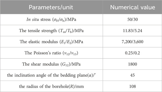
TABLE 2. Basic parameters in MATLAB
4.1 Effect of the in situ stress
The in situ stress significantly influences the deformation and FIP of the borehole. This study set various values of horizontal stress differences to investigate the borehole deformation and distribution of FIP (Figures 5, 6). Figure 5A shows that the length of the major and minor axes and the deflection angle of the deformed elliptical borehole decrease with increasing σh. Further analysis shows that the difference between the length of the major and minor axes first increases and then decreases as increasing σh, reaching a maximum value at 43 MPa. Notably, the deflection angle of the elliptical borehole is invariably greater than zero, indicating that the direction of the major axes of the deformed elliptical borehole is not consistent with the direction of the in situ stress in anisotropic reservoirs. Figure 5B shows that the FIP and initiation angle of both elliptical and circular boreholes increase with increasing σh; when σh is larger than 43.9MPa, the FIP of elliptical boreholes is slightly larger than that of circular boreholes. However, when σh is less than 43.9 MPa, the FIP of elliptical boreholes is smaller than that of circular boreholes, which suggests that borehole deformation arising under in situ stress can either increase or decrease borehole stability, depending on specific geological parameters. The initiation angle of the elliptical borehole is smaller than that of the circular borehole. The difference gradually decreases with increasing σh, which implies that considering the deformation of the boreholes in the calculations yields fracture initiation directions that are closer to the direction of the maximum principal stresses, which is more consistent with the existing experimental results (Heng et al., 2019; Liu et al., 2022).
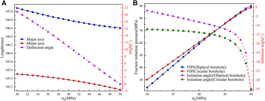
FIGURE 5. (A) Variation of the lengths of the major and minor axes and deflection angle for the elliptical borehole with σh. (B) Variation of the FIP and initiation angle for circular and elliptical boreholes with σh.
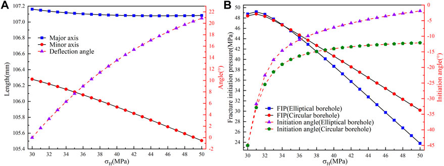
FIGURE 6. (A) Variation of the lengths of the major and minor axes and deflection angle for the elliptical borehole with σH. (B) Variation of the FIP and initiation angle for circular and elliptical boreholes with σH.
According to the observations in Figure 6A, the length of both major and minor axes of the elliptical borehole decreases with increasing σH. Furthermore, the difference between the major and minor axes’ lengths and the deflection angle increases with increasing σH. Figure 6B shows that the FIP and initiation angle of both elliptical and circular boreholes increase with increasing σH. When σH is less than 43.3 MPa, the FIP of elliptical boreholes is marginally more extensive than that of circular boreholes. However, when σH exceeds 43.3 MPa, the FIP of elliptical boreholes becomes smaller than that of circular boreholes. The initiation angle of elliptical boreholes is always smaller than that of circular boreholes, and the difference between the two gradually increases with increasing σH. A comparison between Figures 5, 6 indicates that an increase in the horizontal stress difference results in an increase in the deflection angle and the initiation angle, as well as a decrease in the FIP, which suggests that the study of the effect of in situ stress on borehole deformation and FIP can be simplified to study the impact of horizontal stress differences. However, it is essential to note that it is impossible to establish a direct relationship between the horizontal stress difference and the size of borehole deformation.
4.2 Effect of the bedding inclination angle
The bedding inclination angle (α), defined in this study as the angle between the directions of the bedding plane and the maximum principal stress, was investigated for its effects on borehole deformation and FIP. Figure 7A illustrates that as the α increases, the major axis of the deformed elliptical borehole lengthens. In contrast, the minor axis shortens, and the deflection angle increases and then decreases, reaching a maximum value of 44.33° at 22°. Significantly, there is a distinct alteration of the deflection angle at α when it comes to 22°, signifying a complete exchange of the major and minor axes of the deformation elliptical boreholes. These modifications demonstrate the bedding inclination angle’s significant impact on borehole deformation.
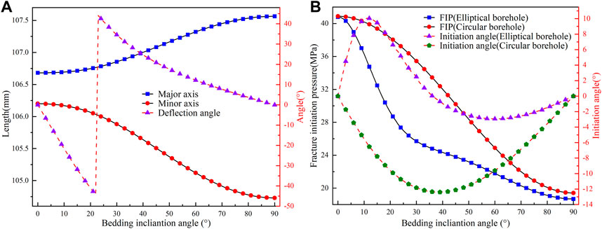
FIGURE 7. (A) Variation of the lengths of the major and minor axes and deflection angle for the elliptical borehole with bedding inclination angle. (B) Variation of the FIP and initiation angle for circular and elliptical boreholes with bedding inclination angle.
It can be seen from Figure 7B that for both elliptical and circular boreholes, the FIPs decrease with increasing α. The difference in FIPs between them first increases and then falls with increasing α, reaching a maximum value of 9.99 MPa at 26°. Based on this observation, we advised choosing formations for field hydraulic fracturing that significantly differ between the directions of the bedding plane and the principal stress to reduce the FIP effectively. Furthermore, the initiation angle for circular boreholes first increases and then decreases as α increases, always resulting in negative values. The maximum initiation angle is approximately 12.4°. However, the initiation angle for elliptical boreholes follows a wavy distribution. It first increases and then decreases as α increases when α is less than 36°, resulting in positive values. The maximum initiation angle is around 10.44°. When α is greater than 36°, the initiation angle first increases and then decreases, but in this case, it results in negative values. Further analysis reveals that the maximum difference between the initiation angles of circular and elliptical boreholes is approximately 17.25°, which indicates that without considering borehole deformation, there may be a significant error in calculating the initiation angle. Therefore, evaluating the effect of borehole deformation when determining the initiation fracture location in hydraulic fracturing is crucial.
4.3 Effect of the elastic anisotropy
Previous research has shown that alterations in the elastic anisotropy ratio (E1/E2) surrounding the borehole result in modifications in the stress distribution around the borehole (Ding et al., 2018). Furthermore, variations in the parameters E1, E2, v12, and v12 in anisotropic materials result in changes in the shear modulus G2. The St. Venant relationship elucidates the connection among these parameters above (Espada and Lamas, 2017; Dambly et al., 2019):
The influence of elastic anisotropy ratio on borehole deformation and FIP was studied using the Saint-Venant relationship, as shown in Figures 8, 9. In Figure 8, we set E2 as constant; an increase in E1/E2 results in an increase in the major axis length of the deformed elliptical borehole. Additionally, the minor axis length first increases and then decreases, while the difference between the two axes decreases and then increases, reaching its minimum value at E1/E2=1.4. The deflection angle follows a similar pattern, first increasing and decreasing, with the maximum deflection angle occurring at E1/E2=1.15. At this ratio, the deflection angle changed to 90°, indicating a complete exchange of positions between the elliptical major and minor axes. These changes mean the significant influence of the elastic anisotropy ratio on the borehole deformation. The FIP of elliptical and circular boreholes decreases with increasing E1/E2. However, the variation in FIP for elliptical boreholes is significantly higher, at 44.29%, compared to only 15.18% for circular boreholes, which suggests that the influence of E1/E2 on deformed elliptical boreholes is more significant and deserves more attention. Furthermore, the difference between FIP for elliptical and circular boreholes initially decreases and then increases with increasing E1/E2. When E1/E2<1.1, the FIP for elliptical boreholes is higher than that for circular boreholes, indicating that a lower elastic anisotropy ratio promotes more excellent stability for circular boreholes after deformation. The initiation angle for circular boreholes increases with increasing E1/E2, reaching a maximum value of approximately 16.99°, which indicates that the fracture initiation directions largely coincide with the direction of the maximum principal stresses. In the case of elliptical boreholes, however, the initiation angle initially increases and then decreases as the E1/E2 increases. It is worth noting that for E1/E2<1.2, the initiation angle is about 100°, suggesting that when elastic anisotropy is low, the fracture initiation direction of deformed elliptical boreholes is closer to the direction of minimum principal stress.
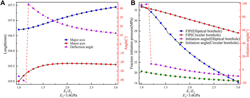
FIGURE 8. (A) Variation of the lengths of the major and minor axes and deflection angle for the elliptical borehole with E1/E2 (E2=3.6 GPa). (B) Variation of the FIP and initiation angle for circular and elliptical boreholes with E1/E2.
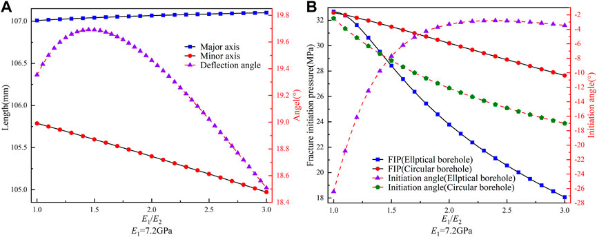
FIGURE 9. (A) Variation of the lengths of the major and minor axes and deflection angle for the elliptical borehole with E1/E2 (E1=7.2 GPa). (B) Variation of the FIP and initiation angle for circular and elliptical boreholes with E1/E2.
In Figure 9, we set E1 as constant. As E1/E2 increase, the length of the major and minor axes of the elliptical borehole increase and decrease, respectively, and the difference between them constantly increases. Furthermore, the deflection angle increases and then decreases, reaching a maximum value of 19.69° at E1/E2=1.45. However, the total change in the deflection angle is about 6%. Comparing this with Figure 8A, it is clear that there are different distribution patterns in terms of the size of the borehole deformation and the deflection angle. Therefore, we considered that the specific values of E1 and E2 are the main factors affecting the borehole deformation, not just the E1/E2. By comparing and analyzing Figure 8B and Figure 9B, we found that the FIP values in both figures are identical when E1/E2 is the same, which indicates that when calculating the FIP, only the elastic anisotropy ratio needs to be considered, without specifying the actual values. However, the distribution pattern of the initiation angle differs between the two figures. In Figure 9B, the initiation angle for circular boreholes decreases with increasing E1/E2. In contrast, the initiation angle for elliptical boreholes first increases and then falls, which suggests that the specific values of E1 and E2 are essential factors affecting the initiation angle.
4.4 Effect of Poisson’s ratio anisotropy
This section investigated the influence of Poisson’s ratio anisotropy on borehole deformation and FIP. In Figure 10, we set v13 as constant; as v12/v13 increases, the major axis length of the borehole increases, while the minor axis length first increases and then decreases, reaching its maximum value at v12/v13=2.45. Furthermore, the deflection angle decreases continuously, with a maximum change of up to 59%. The maximum difference in deformation of the major and minor axes of the elliptical borehole is 0.28 mm. These results indicate that Poisson’s ratio anisotropy has minimal influence on the borehole deformation but significantly influences the deflection angle. As shown in Figure 10B, the FIP decreases with increasing v12/v13 for both the elliptical and circular boreholes. Furthermore, the difference between them first increases and then decreases, reaching a maximum value of 7.59 MPa at v12/v13=2.7. This observation indicates that high Poisson’s ratio anisotropy can reduce the FIP after borehole deformation. Therefore, when conducting hydraulic fracturing in the field, reservoirs with high Poisson’s ratio anisotropy could be selected to arrange the boreholes to minimize the FIP effectively. Moreover, the initiation angles of both elliptical and circular boreholes decrease with increasing v12/v13, and the initiation angle of elliptical boreholes is consistently smaller than that of circular boreholes. This finding suggests that borehole deformation brings the direction of fracture initiation closer to the direction of the maximum principal stress, consistent with existing experimental results (Heng et al., 2019; Liu et al., 2022).
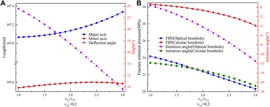
FIGURE 10. (A) Variation of the lengths of the major and minor axes and deflection angle for the elliptical borehole with v12/v13 (v13=0.2). (B) Variation of the FIP and initiation angle for circular and elliptical boreholes with v12/v13.
In Figure 11, we set v12 as a fixed value and observed that as v12/v13 increases, the length of the major and minor axes of the elliptical borehole increases and decreases, respectively. The maximum change in size is about 0.06 mm. Additionally, the deflection angle continues to decline. Compared to Figure 10A, it is clear that Poisson’s ratio anisotropy ratio has no significant influence on the length of the major and minor axes of the elliptical borehole. However, it does have a notable effect on the deflection angle. Nevertheless, we cannot predict the trend of the deflection angle solely based on Poisson’s ratio anisotropy ratio trends. Furthermore, the analysis of Figure 10B reveals that as the v12/v13 increases, the FIPs of elliptical and circular boreholes decrease. The difference between them initially decreases and then stabilizes. Moreover, the initiation angle of elliptical boreholes decreases while circular boreholes increase, albeit with a more minor change. We compared this to Figure 10B and could predict the FIP trend based on Poisson’s anisotropy ratio. However, we could not predict the trend of the initiation angle.
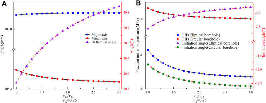
FIGURE 11. (A) Variation of the lengths of the major and minor axes and deflection angle for the elliptical borehole with v12/v13 (v12=0.25). (B) Variation of the FIP and i/nitiation angle for circular and elliptical boreholes with v12/v13.
4.5 Effect of strength anisotropy
Based on Equation 5, the strength anisotropy does not affect the borehole deformation but affects the FIP. To examine this effect, we kept the rock material’s tensile strength constant while adjusting the bedding plane’s tensile strength to achieve varying degrees of anisotropy. Figure 12 illustrates the relationship between the strength anisotropy ratio (Tm/Tb), FIP, and initiation angle for both elliptical and circular boreholes. As Tm/Tb increases, the FIP and angle decrease for both elliptical and circular boreholes. Additionally, the difference in FIPs between elliptical and circular boreholes decreases while the difference in initiation angles increases. Despite their lack of impact on borehole deformation, these findings highlight the significance of considering strength anisotropy in calculating FIPs and initiation angles for deformed elliptical boreholes.
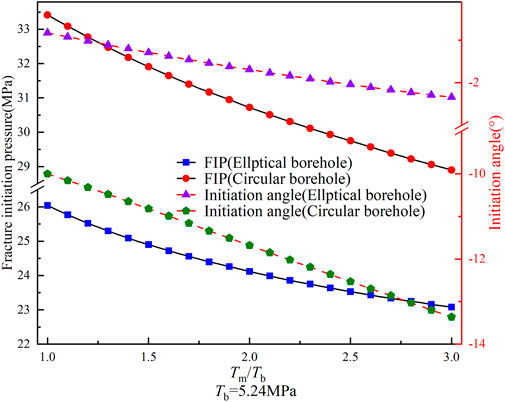
FIGURE 12. Variation of the FIP and initiation angle for circular and elliptical boreholes with Tm/Tb (Tb=5.24 MPa).
5 Discussion
The analysis of logged data suggests that in layered reservoirs, circular boreholes can be transformed into elliptical boreholes under in situ stress (Zoback et al., 2003; Pierdominici et al., 2020; Han et al., 2021). Various researchers have created models to forecast the extent of borehole deformation (Zou et al., 2018; Fang et al., 2022; Han et al., 2023), but these models do not account for the impact of elastic anisotropy in layered reservoirs, which could affect the accuracy of the forecasts (Ma et al., 2019). Our study factors in layered reservoirs’ elastic and stress anisotropy (Abdulelah et al., 2018; Qu et al., 2022b; Lu et al., 2022), and develops a model to anticipate the extent of deformation in vertical or horizontal boreholes. By substituting the reservoir parameters into the model, we discover that circular boreholes in layered reservoirs also transform into elliptical boreholes, which is consistent with previous findings (Zou et al., 2018; Fang et al., 2022; Han et al., 2023). Unexpectedly, our calculations indicate that the major axis direction of the deformed boreholes is incongruent with the direction of the in situ stress, differing from the previous model but aligning more closely with the logging data (Pierdominici et al., 2020), which highlights the superiority of our proposed model.
Using models and logging data, we have demonstrated that circular boreholes deform into elliptical boreholes under the influence of in situ stress and elastic anisotropy. Previous studies have indicated that the change in borehole shape impacts the FIP (Qi et al., 2018; Zheng et al., 2023). Several models have been developed to predict the FIP of elliptical boreholes (Chen et al., 2020; Zhong et al., 2021), but these models do not consider the effect of mechanical anisotropy in layered reservoirs. We have developed an improved FIP prediction model based on the forecasted borehole deformation and validated its accuracy by comparing it with the models of Aadnoy and Angell-olsen (1995) and Ge et al. (2019). Zang et al. (2023) observed, through digital image correlation during SC-CO2 fracturing in the laboratory, that there is a strain concentration near the borehole before fracturing, which can cause borehole deformation, which suggests that our proposed model can also be used to predict the FIP of bedding shales for hydraulic fracturing in laboratory experiments (Liu et al., 2022). Based on the experimental findings by Liu et al. (2022), we have conducted a comparative analysis of our model and that of Ma et al. (2022). The results indicate a 47.6% enhancement in our model’s accuracy, demonstrating our proposed model’s advanced capability.
We compared the impacts of in situ stress, bedding inclination, and anisotropy parameters on FIP and initiation angle in circular and elliptical boreholes. Our findings indicate that elliptical boreholes may exhibit higher or lower initiation pressures than circular boreholes, depending on specific geologic parameters, which differs from previous models (Chen et al., 2020; Zhong et al., 2021; Zheng et al., 2023) due to the absence of a relationship between the amount of borehole deformation and FIP in the previous models. Furthermore, our proposed model predicts a deviation angle between the fracture initiation direction and the maximum principal stress direction of no more than 10°. In contrast, the deviation angle in the previous model is significantly larger (Heng et al., 2021; Ma et al., 2022). However, the experimental results demonstrate that the fracture initiation direction in anisotropic rocks aligns closely with the direction of maximum stress (Heng et al., 2019; Liu et al., 2022), highlighting the superior predictive performance of our model in determining the initiation angle.
The model proposed in this study is a two-dimensional model suitable only for horizontal or vertical boreholes. In contrast, inclined boreholes are more commonly encountered in on-site hydraulic fracturing operations (Ma et al., 2022; Zheng et al., 2023). Furthermore, the proposed model solely focuses on the tensile failure mode of the rock matrix. Previous experiments have demonstrated that layered rocks in hydraulic fracturing can exhibit various failure modes, including tensile and shear failure modes of the rock matrix and tensile and shear failure modes of the bedding plane (Li et al., 2018; Heng et al., 2021). Therefore, future research should optimize the proposed model by considering these two aspects to enhance its universality.
6 Conclusion
We formulated a model for predicting the vertical borehole deformation in layered reservoirs and developed a novel model for forecasting fracture initiation pressure (FIP) in hydraulic fracturing based on the expected deformation. We validated the proposed model’s accuracy against previous models and experimental data. Furthermore, we examined the impact of in situ stress, bedding inclination, and reservoir anisotropic parameters on borehole deformation. We compared FIP and initiation angle changes in undeformed and deformed boreholes under varying conditions. The key findings of our study are summarized as follows.
1. The circular vertical boreholes in layered reservoirs change to elliptical due to in situ stress, and the major axis of elliptical boreholes deviates from the direction of the maximum principal stress.
2. Depending on the specific geological conditions, the borehole deformation can increase or decrease the FIP in hydraulic fracturing. Additionally, alterations in factors such as in situ stress, bedding inclination angle, and elastic modulus can result in more pronounced variations in FIP in elliptical boreholes than circular ones.
3. The initiation angles of elliptical boreholes are within 10°, which are notably lower when compared to that of circular boreholes, and the alteration in the in situ stress, bedding inclination angle, and elastic modulus result in minor modifications in the initiation angles of elliptical boreholes in comparison to those of circular boreholes. The borehole deformations can better explain the fracture propagation in hydraulic fracturing.
Data availability statement
The raw data supporting the conclusion of this article will be made available by the authors, without undue reservation.
Author contributions
YW: Methodology, Writing–original draft. MW: Investigation, Writing–original draft. ZN: Software, Writing–original draft. ZC: Data curation, Writing–original draft. RM: Formal Analysis, Writing–original draft. JZ: Writing–original draft, Writing–review and editing, Conceptualization, Validation.
Funding
The author(s) declare financial support was received for the research, authorship, and/or publication of this article. This study was financially supported by the Graduate Research and Innovation Foundation of Chongqing, China (No. CYB21024).
Conflict of interest
Authors YW, MW, ZN, ZC, and RM were employed by Pingdingshan Tianan Coal Mining Co., Ltd.
The remaining author declares that the research was conducted in the absence of any commercial or financial relationships that could be construed as a potential conflict of interest.
The reviewer XZ declared a shared affiliation with the author JZ to the handling editor at time of review.
Publisher’s note
All claims expressed in this article are solely those of the authors and do not necessarily represent those of their affiliated organizations, or those of the publisher, the editors and the reviewers. Any product that may be evaluated in this article, or claim that may be made by its manufacturer, is not guaranteed or endorsed by the publisher.
References
Aadnoy, B. S., and Angell-Olsen, F. (1995). Some effects of ellipticity on the fracturing and collapse behavior of a borehole. Int. J. rock Mech. Min. Sci. Geomech. Abstr. 32, 621–627. doi:10.1016/0148-9062(95)00016-A
Aadnoy, B. S., and Chenevert, M. E. (1987). Stability of highly inclined boreholes. SPE Drill. Eng. 2 (4), 364–374. doi:10.2118/16052-PA
Abdulelah, H., Mahmood, S., Al-Hajri, S., Hakimi, M., and Padmanabhan, E. (2018). Retention of hydraulic fracturing water in shale: the influence of anionic surfactant. Energies 11, 3342. doi:10.3390/en11123342
Chen, Y. L., Liu, Z., Zhang, X., He, S. M., Ma, D. X., and Zhou, J. (2020). Research on the collapse pressure of an elliptical wellbore considering the effect of weak planes. Energ Source Part A 42, 2103–2119. doi:10.1080/15567036.2019.1607929
Constant, W. D., and Jr, A. T. B. (1988). Fracture-gradient prediction for offshore wells. SPE Drill. Eng. 3 (02), 136–140. doi:10.2118/15105-PA
Dambly, M. L. T., Nejati, M., Vogler, D., and Saar, M. O. (2019). On the direct measurement of shear moduli in transversely isotropic rocks using the uniaxial compression test. Int. J. Rock Mech. Min. Sci. 113, 220–240. doi:10.1016/j.ijrmms.2018.10.025
Detournay, E., and Cheng, A. H.-D. (1988). Poroelastic response of a borehole in a non-hydrostatic stress field. Int. J. rock Mech. Min. Sci. Geomech. Abstr. 25 (3), 171–182. doi:10.1016/0148-9062(88)92299-1
Ding, Y., Luo, P. Y., Liu, X. J., and Liang, L. X. (2018). Wellbore stability model for horizontal wells in shale formations with multiple planes of weakness. J. Nat. Gas. Sci. Eng. 52, 334–347. doi:10.1016/j.jngse.2018.01.029
Do, D.-P., Tran, N.-H., Hoxha, D., and Dang, H.-L. (2017). Assessment of the influence of hydraulic and mechanical anisotropy on the fracture initiation pressure in permeable rocks using a complex potential approach. Int. J. Rock Mech. Min. Sci. 100, 108–123. doi:10.1016/j.ijrmms.2017.10.020
Eaton, B. A. (1969). Fracture gradient prediction and its application in oilfield operations. J. Pet. Technol. 21, 1353–1360. doi:10.2118/2163-PA
Espada, M., and Lamas, L. (2017). Back analysis procedure for identification of anisotropic elastic parameters of overcored rock specimens. Rock Mech. Rock Eng. 50 (3), 513–527. doi:10.1007/s00603-016-1129-3
Espinoza, D. N., Vandamme, M., Dangla, P., Pereira, J.-M., and Vidal-Gilbert, S. (2013). A transverse isotropic model for microporous solids: application to coal matrix adsorption and swelling. J. Geophys. Res. Solid Earth 118, 6113–6123. doi:10.1002/2013JB010337
Fang, X. X., Zhang, J. B., Liu, T., Zhang, Z., and Li, F. L. (2022). New prediction method of horizontal principal stress of deep tight reservoirs. Sci. Rep. 12, 12908. doi:10.1038/s41598-022-16954-1
Gao, Y. B., and Ren, J. (2022). Study on the effect of borehole size on gas extraction borehole strength and failure mode. ACS Omega 7, 25635–25643. doi:10.1021/acsomega.2c02834
Ge, Z. L., Zhong, J. Y., Lu, Y. Y., Cheng, L., Zheng, J. W., Zhou, Z., et al. (2019). Directional distance prediction model of slotting–directional hydraulic fracturing (SDHF) for coalbed methane (CBM) extraction. J. Pet. Sci. Eng. 183, 106429. doi:10.1016/j.petrol.2019.106429
Gupta, D., and Zaman, M. (1999). Stability of boreholes in a geologic medium including the effects of anisotropy. Appl. Math. Mech. 20, 837–866. doi:10.1007/BF02452483
Haimson, B., and Lee, H. (2004). Borehole breakouts and compaction bands in two high-porosity sandstones. Int. J. Rock Mech. Min. Sci. 41, 287–301. doi:10.1016/j.ijrmms.2003.09.001
Han, H. X., Yin, S. D., Chen, Z. H., and Dusseault, M. B. (2021). Estimate of in situ stress and geomechanical parameters for Duvernay Formation based on borehole deformation data. J. Pet. Sci. Eng. 196, 107994. doi:10.1016/j.petrol.2020.107994
Han, Z. Q., Li, M. H., Wang, C., Wang, J. C., and Huang, X. H. (2023). Application and discussion of the borehole radial deformation method in deep borehole geostress measurement. Front. Earth Sci. 11, 1102276. doi:10.3389/feart.2023.1102276
He, S., Qin, Q. R., Li, H., and Wang, S. L. (2022b). Deformation differences in complex structural areas in the southern sichuan basin and its influence on shale gas preservation: a case study of changning and luzhou areas. Front. Earth Sci. 9, 818155. doi:10.3389/feart.2021.818534
He, S., Qin, Q. R., Li, H., and Zhao, S. X. (2022a). Geological characteristics of deep shale gas in the silurian longmaxi formation in the southern sichuan basin, China. Front. Earth Sci. 9, 818543. doi:10.3389/feart.2021.818155
Heng, S., Liu, X., Li, X. Z., Zhang, X. D., and Yang, C. H. (2019). Experimental and numerical study on the non-planar propagation of hydraulic fractures in shale. J. Pet. Sci. Eng. 179, 410–426. doi:10.1016/j.petrol.2019.04.054
Heng, S., Zhao, R. T., Li, X. Z., and Guo, Y. Y. (2021). Shear mechanism of fracture initiation from a horizontal well in layered shale. J. Nat. Gas. Sci. Eng. 88, 103843. doi:10.1016/j.jngse.2021.103843
Huang, B. X., Li, H., Zhao, X. L., and Ying, Y. K. (2023a). Fracturing criterion of rock hydrofracturing considering pore pressure effect. Front. Earth Sci. 11, 111206. doi:10.3389/feart.2023.1111206
Huang, L. K., Tan, J., Fu, H. F., Liu, J. J., Chen, X. Y., Lao, X. C., et al. (2023b). The non-plane initiation and propagation mechanism of multiple hydraulic fractures in tight reservoirs considering stress shadow effects. Eng. Fract. Mech. 292, 109570. doi:10.1016/j.engfracmech.2023.109570
Hubbert, M. K., and Willis, D. G. (1957). Mechanics of hydraulic fracturing. AIME Pet. Trans. 210, 153–168. doi:10.2118/686-G
Li, C. F., and Zhang, Z. N. (2019). Modeling shale with consideration of bedding planes by cohesive finite element method. Theor. App. Mech. Lett. 9, 397–402. doi:10.1016/j.taml.2019.06.003
Li, H., Zhou, J. L., Mou, X. Y., Guo, H. X., Wang, X. X., An, H. Y., et al. (2022). Pore structure and fractal characteristics of the marine shale of the longmaxi formation in the changning area, southern sichuan basin, China. Front. Earth Sci. 10, 1018274. doi:10.3389/feart.2022.1018274
Li, N., Zhang, S. C., Zou, Y. S., Ma, X. F., Zhang, Z. P., Li, S. H., et al. (2018). Acoustic emission response of laboratory hydraulic fracturing in layered shale. Rock Mech. Rock Eng. 51, 3395–3406. doi:10.1007/s00603-018-1547-5
Liang, X., Hou, P., Xue, Y., Gao, Y. N., Gao, F., Liu, J., et al. (2022). Role of fractal effect in predicting crack initiation angle and its application in hydraulic fracturing. Rock Mech. Rock Eng. 55, 5491–5512. doi:10.1007/s00603-022-02940-6
Liu, Q., Li, J. L., Liang, B., Liu, J. J., Sun, W. J., He, J., et al. (2023). Complex wettability behavior triggering mechanism on imbibition: a model construction and comparative study based on analysis at multiple scales. Energy 275, 127434. doi:10.1016/j.energy.2023.127434
Liu, Q., Liang, B., Sun, W. J., Zhao, H., Hao, J. F., and Hou, M. R. (2022). Experimental study on hydraulic fracturing of bedding shale considering anisotropy effects. ACS Omega 7, 22698–22713. doi:10.1021/acsomega.2c02157
Lu, Y. Y., Zheng, J. W., Ge, Z. L., Zhou, Z., Wang, H. M., and Zhang, L. (2022). A study of variation in the initiation pressure and fracture distribution patterns of raw coal in SC-CO2 fracturing under the true tri-axial system. Rock Mech. Rock Eng. 55, 3425–3438. doi:10.1007/s00603-022-02800-3
Ma, T. S., Gui, J. C., and Chen, P. (2021). Logging evaluation on mechanical-damage characteristics of the vicinity of the wellbore in tight reservoirs. J. Pet. Explor Prod. Technol. 11, 3213–3224. doi:10.1007/s13202-021-01200-7
Ma, T. S., Liu, Y., Chen, P., Wu, B. S., Fu, J. H., and Guo, Z. X. (2019). Fracture-initiation pressure prediction for transversely isotropic formations. J. Pet. Sci. Eng. 176, 821–835. doi:10.1016/j.petrol.2019.01.090
Ma, T. S., Wang, H. N., Liu, Y., Shi, Y. F., and Ranjith, P. G. (2022). Fracture-initiation pressure model of inclined wells in transversely isotropic formation with anisotropic tensile strength. Int. J. Rock Mech. Min. Sci. 159, 105235. doi:10.1016/j.ijrmms.2022.105235
Ma, T. S., Wu, B. S., Fu, J. H., Zhang, Q. G., and Chen, P. (2017). Fracture pressure prediction for layered formations with anisotropic rock strengths. J. Nat. Gas. Sci. Eng. 38, 485–503. doi:10.1016/j.jngse.2017.01.002
Nova, R., and Zaninetti, A. (1990). An investigation into the tensile behaviour of a schistose rock. Int. J. rock Mech. Min. Sci. Geomech. Abstr. 27, 231–242. doi:10.1016/0148-9062(90)90526-8
Ong, S. H., and Roegiers, J. C. (1995). “Fracture initiation from inclined wellbores in anisotropic formations,” in International meeting on Petroleum engineering (Beijing, China: IEEE), 14-17. (SPE 29993).
Oriji, A. B., and Ogbonna, J. (2012). “A new fracture gradient prediction technique that shows good results in gulf of Guinea,” in All days (abu dhabi, UAE: spe), SPE-161209-MS (UAE: SPE). doi:10.2118/161209-MS
Pierdominici, S., Millett, J., Kuck, J., Thomas, D., Jerram, D., Planke, S., et al. (2020). Stress field interactions between overlapping shield volcanoes: borehole breakout evidence from the island of Hawaii, USA. J. Geophys. Res. Solid Earth 125, e2020JB019768. doi:10.1029/2020JB019768
Prioul, R., Karpfinger, F., Deenadayalu, C., and Suarez-Rivera, R. (2011). “Improving fracture initiation predictions on arbitrarily oriented wells in anisotropic shales,” in All days (calgary, alberta, Canada: spe), SPE-147462-MS (Canada: SPE). doi:10.2118/147462-MS
Qi, D. X., Li, L. J., and Jiao, Y. S. (2018). The stress state around an elliptical borehole in anisotropy medium. J. Pet. Sci. Eng. 166, 313–323. doi:10.1016/j.petrol.2018.03.013
Qu, G. Z., Su, J., Zhao, M., Bai, X. J., Yao, C. J., and Peng, J. (2022b). Optimizing composition of fracturing fluids for energy storage hydraulic fracturing operations in tight oil reservoirs. Energies 15, 4292. doi:10.3390/en15124292
Qu, H., Tang, S. M., Liu, Y., Huang, P. P., Wu, X. G., Liu, Z. H., et al. (2022a). Characteristics of complex fractures by liquid nitrogen fracturing in brittle shales. Rock Mech. Rock Eng. 55 (4), 1807–1822. doi:10.1007/s00603-021-02767-7
Ren, L., Jiang, H., Zhao, J. Z., Lin, R., Wang, Z. H., and Xu, Y. (2022). Theoretical study on fracture initiation in deep perforated wells with considering wellbore deformation. J. Pet. Sci. Eng. 211, 110141. doi:10.1016/j.petrol.2022.110141
Sesetty, V., and Ghassemi, A. (2018). Effect of rock anisotropy on wellbore stresses and hydraulic fracture propagation. Int. J. Rock Mech. Min. Sci. 112, 369–384. doi:10.1016/j.ijrmms.2018.09.005
Shou, Y. D., and Zhou, X. P. (2021). A coupled hydro-mechanical non-ordinary state-based peridynamics for the fissured porous rocks. Eng. Anal. Bound Elem. 123, 133–146. doi:10.1016/j.enganabound.2020.12.001
Song, R., Liu, J. J., and Cui, M. M. (2017). A new method to reconstruct structured mesh model from micro-computed tomography images of porous media and its application. Int. J. Heat. Mass Tran 109, 705–715. doi:10.1016/j.ijheatmasstransfer.2017.02.053
Song, R., Wang, Y., Ishutov, S., Zambrano-Narvaez, G., Hodder, J. K., Chalaturnyk, R. J., et al. (2020). A comprehensive experimental study on mechanical behavior, microstructure and transport properties of 3D-printed rock analogs. Rock Mech. Rock Eng. 53 (12), 5745–5765. doi:10.1007/s00603-020-02239-4
Wu, F. P., Li, D., Fan, X. Z., Liu, J., and Li, X. J. (2020). Analytical interpretation of hydraulic fracturing initiation pressure and breakdown pressure. J. Nat. Gas. Sci. Eng. 76, 103185. doi:10.1016/j.jngse.2020.103185
Wu, M. Y., Jiang, C. B., Song, R., Liu, J. J., Li, M. H., Liu, B., et al. (2023). Comparative study on hydraulic fracturing using different discrete fracture network modeling: insight from homogeneous to heterogeneity reservoirs. Eng. Fract. Mech. 284, 109274. doi:10.1016/j.engfracmech.2023.109274
Zang, Y. X., Wang, Q., Wang, H. Z., Wang, B., Tian, K. J., Wang, T. Y., et al. (2023). Laboratory visualization of supercritical CO2 fracturing in tight sandstone using digital image correlation method. Geoenergy Sci. Eng. 225, 211556. doi:10.1016/j.geoen.2023.211556
Zhai, C., Xu, Y. M., Xiang, X. W., Yu, X., Zou, Q. N., and Zhong, C. (2015). A novel active prevention technology for borehole instability under the influence of mining activities. J. Nat. Gas. Sci. Eng. 27, 1585–1596. doi:10.1016/j.jngse.2015.10.024
Zhang, Y. F., Long, A. F., Zhao, Y., Wang, C. L., Wu, S. F., and Huang, H. S. (2023). Impacts of wellbore orientation with respect to bedding inclination and injection rate on laboratory hydraulic fracturing characteristics of Lushan shale. Fuel 353 (1), 129220. doi:10.1016/j.fuel.2023.129220
Zhang, Y. S., Zhang, J. C., Yuan, B., and Yin, S. X. (2018). In situ stresses controlling hydraulic fracture propagation and fracture breakdown pressure. J. Pet. Sci. Eng. 164, 164–173. doi:10.1016/j.petrol.2018.01.050
Zhao, H., Li, W., Wang, L., Fu, J., Xue, Y. L., Zhu, J. J., et al. (2022). The influence of the distribution characteristics of complex natural fracture on the hydraulic fracture propagation morphology. Front. Earth Sci. 9, 784951. doi:10.3389/feart.2021.784931
Zhao, Z., Zhou, X. P., and Qian, Q. H. (2020a). Fracture characterization and permeability prediction by pore scale variables extracted from X-ray CT images of porous geomaterials. Sci. China Technol. Sci. 63 (5), 755–767. doi:10.1007/s11431-019-1449-4
Zhao, Z., and Zhou, Z. P. (2020b). Digital voxel-based fracture extraction: insights to characterization of single fracture flow and anisotropy permeability. J. Nat. Gas. Sci. Eng. 84, 103635. doi:10.1016/j.jngse.2020.103635
Zheng, J. W., Ge, Z. L., Lu, Y. Y., Zhou, Z., Zhou, J., and Fu, W. Y. (2023). Prediction of fracture initiation pressure for slotting-directional hydraulic fracturing based on the anisotropy of coal. J. Energy Resour. Technol. 145. doi:10.1115/1.4062960
Zhong, J. Y., Ge, Z. L., Lu, Y. Y., Zhou, Z., and Zheng, J. W. (2021). Prediction of fracture initiation pressure in multiple failure hydraulic fracturing modes: three-dimensional stress model considering borehole deformation. J. Pet. Sci. Eng. 199, 108264. doi:10.1016/j.petrol.2020.108264
Zhou, X. P., Zhao, Z., and Li, Z. (2020). Cracking behaviors and hydraulic properties evaluation based on fractural microstructure models in geomaterials. Int. J. Rock Mech. Min. Sci. 130, 104304. doi:10.1016/j.ijrmms.2020.104304
Zhu, H. Y., Guo, J. C., Zhao, X. C., Lu, Q. L., Luo, B., and Feng, Y. C. (2014). Hydraulic fracture initiation pressure of anisotropic shale gas reservoirs. ge?ome?Chem. Eng. 7, 403–430. doi:10.12989/GAE.2014.7.4.403
Zoback, M. D., Barton, C. A., Brudy, M., Castillo, D. A., Finkbeiner, T., Grollimund, B. R., et al. (2003). Determination of stress orientation and magnitude in deep wells. Int. J. Rock Mech. Min. Sci. 40, 1049–1076. doi:10.1016/j.ijrmms.2003.07.001
Zou, X. J., Wang, C. Y., and Han, Z. Q. (2018). A proposed method for estimating in situ stress direction using panoramic stereo-pair imaging and stressed borehole geometric shapes. Int. J. Rock Mech. Min. Sci. 104, 94–99. doi:10.1016/j.ijrmms.2018.02.010
Appendix A
The intrinsic equation, stress equilibrium equation, and strain compatibility equation in the bedding plane coordinate system under generalized plane strain are as follows (Qi et al., 2018).
Where
Where E1 and E2 are the elastic modulus in the directions of x1-axis, and y1-axis, respectively, GPa; G12 is the elastic modulus in x1oy1 coordinate system, GPa; v12 and v32 are the Poisson’s ratio in the directions of x1-axis, and y1-axis, respectively.
The stress function F (x, y) was introduced based on Equation (A2) and by substituting it into Equations (A1) and A3 yields (Aadnoy and Chenevert, 1987).
By introducing linear differential operators
Equation (A5) has two pairs of conjugate complex roots:
We expressed the stress function F (x, y) as follows:
where Re is the real part of the complex number, and F1 (z1) and F2 (z2) are arbitrary analytic functions of the complex variables z1 and z2. To simplify calculations, we introduced the following functions can be:
Substituting Equation (A8) into Equation (A7) and subsequently taking the derivative yields:
Based on Equation (A9), the stress component in the anisotropic medium can be represented by the analytical function as:
Where σx1 and σy1 are the normal stress in the directions of x1-axis and y1-axis, respectively, MPa.
The stress boundary condition can be determined by the external force px and py applied as:
The equations to express the external forces px and py can be derived based on the boundary conditions shown in Figure 1 as follows:
Where R is the radius of the borehole and the slotting depth, m.
Substituting Equation (A12) into Equation (A11) and subsequently making the arc integral yields:
Equation (A13) can be expanded into a Fourier series focusing on θ as follows:
where i and e are the imaginary unit and natural number, respectively. By comparing Equations (A13) and (A14) one obtains:
To ascertain the analytical function φk (zk) (k=1, 2) based on the stress boundary conditions, it is essential to map the circular domain on the complex plane zk (i.e., the x2oy2 plane) to the outer region of the unit circle on the ξk plane, with the corresponding mapping function is:
Thus, on the borehole wall:
As the distance is augmented, the pressure induced by the surface forces that act on the well wall gradually decreases, the intricate analytical function can be posited as follows:
The specific form of the analytic function can be derived by comparing Equations (A18) and (A16) as:
The deformation of the borehole caused by in situ stress can be determined using the intrinsic equation:
where
By comparing Equations (A17) and (A19) into Equation (A20) and subsequently simplifying, a specific formula for the displacement yields:
The relationship satisfied by the two roots of Equation (A5) is as follows:
To eliminate the Re sign in Eq. 22, one may assume that
Appendix B
The equation for an ellipse is typically represented in the following standard form:
By rotating the coordinate axes of the standard equation by β, the general equation of the ellipse (Eq. 4) can be obtained. The relationship between the corresponding coordinates can be expressed as follows:
Substituting Eq. (B2) into Eq. (B1) and simplifying yields:
We compared Equations (B3) and (4) yields:
The solution to Eq. (B4) provides the values for the major axis a, the minor axis b, and the angle β between the directions of the major axis and the x2 axes of the elliptical borehole. These values are illustrated in Equation 5.
Appendix C
To acquire the flexibility matrix of the medium in the x3oy3 coordinate system, we transform on the flexibility matrix in the x2oy2 coordinate system as follows (Ma et al., 2022):
where
where
Equation (A5) can be modified in the following form:
It is typical for the Eigen Equation (C4) to exhibit two pairs of conjugate complex roots denoted as and
The stress equations are derived using the method described in Appendix A, but the stress boundary conditions are changed. We can modify Equation 12 by considering the effects of fracturing fluid injection pressure and in situ stress (Zheng et al., 2023).
Where pw is the injection pressure of fracturing fluid, MPa.
The final analytical functions obtained from Equation (C5) based on the calculation process in Appendix A are as follows:
Equation 9 can be obtained by taking the derivatives of φ1 (z1) and φ2 (z2) in Equation (C6) for z1 and z2, respectively.
Keywords: borehole deformation, fracture initiation pressure, hydraulic fracturing, anisotropy, initiation angle
Citation: Wang Y, Wang M, Niu Z, Chen Z, Min R and Zheng J (2024) Fracture initiation pressure prediction of hydraulic fracturing for layered reservoirs considering borehole deformation. Front. Earth Sci. 11:1334175. doi: 10.3389/feart.2023.1334175
Received: 06 November 2023; Accepted: 18 December 2023;
Published: 08 January 2024.
Edited by:
Hu Li, Southwest Petroleum University, ChinaReviewed by:
Xiaoping Zhou, Chongqing University, ChinaLiuke Huang, Southwest Petroleum University, China
Jun Lu, Shenzhen University, China
Copyright © 2024 Wang, Wang, Niu, Chen, Min and Zheng. This is an open-access article distributed under the terms of the Creative Commons Attribution License (CC BY). The use, distribution or reproduction in other forums is permitted, provided the original author(s) and the copyright owner(s) are credited and that the original publication in this journal is cited, in accordance with accepted academic practice. No use, distribution or reproduction is permitted which does not comply with these terms.
*Correspondence: Jingwei Zheng, emhlbmdqaW5nd2VpQGNxdS5lZHUuY24=