 Chao Wang
 Zhiqiang Yin1,2
94% of researchers rate our articles as excellent or good
Learn more about the work of our research integrity team to safeguard the quality of each article we publish.
Find out more
ORIGINAL RESEARCH article
Front. Earth Sci., 29 December 2023
Sec. Geohazards and Georisks
Volume 11 - 2023 | https://doi.org/10.3389/feart.2023.1327074
In order to solve the problem of stress concentration on the roof of the mining trench, reduce the risk of sudden collapse of the roof overburden and disturbance, improve the control effect of the surrounding rock of the roof cutting and retaining roadway, and reduce the construction cost of mining tunnels, a new type of pouch sealing technology has been developed. By using on-site testing methods, the optimal sealing material ratio was optimized, and the crack propagation law and roof cutting effect of the 11503 W working face in Zhaizhen Coal Mine, Shandong Province were studied under hole spacing of 0.7, 1.0, and 1.1 meters and different sealing methods. The results show that using 1.5 m single pouch sealing technology in the blasting test, when the water cement ratio of the sealing material is 1:1, the required sealing strength and sealing temperature can be achieved, and there will be no punching phenomenon. When the spacing between holes is 1 m, the blasting effect is optimal, with a single hole effectively reaching a cutting seam length of about 0.5 m. There are obvious through cracks in the cave, with a total length of about 7 meters. After using the new pouch sealing technology for blasting, the displacement and bottom drum volume on both sides of the tunnel are lower than those of the traditional yellow mud sealing method, and the bottom drum volume is reduced by 37% and 53%, respectively. Based on comprehensive theoretical analysis and on-site experiments, the optimal hole spacing is determined to be 1 m, and the pouch sealing effect is good.
In recent years, top-cutting technology based on the “top-cutting short-wall beam theory” has been applied and promoted in many domestic mines. This technology uses directional polygraphic blasting technology before the coal seam is retrieved to pre-crack the top plate along the side of the mining area in the retrieval roadway (Meng et al., 2020; Yin et al., 2021). Then, after the coal seam is retrieved, the top plate will automatically cut down along the pre-cracking slit to form the roadway gang under the action of mine pressure, thus realizing “roadway formation”. After the roof plate is cut off, the long wall rock beam becomes a short arm rock beam, the stress transmission chain of the roof rock layer is cut off, and the periodic pressure strength of the roof plate will is greatly weakened. After the top slab collapses, a roadway gang is formed, which will isolate the mining area and automatically form a roadway that will be used for the next working face, finally realizing that only one roadway needs to be dug for a mining face. The new roadway is located in the pressure relief zone, avoiding the influence of high-stress areas and eliminating the power source of underground power disaster breeding. As the depth of coal mining in China increases, underground stresses become more complex. Therefore simple, timely, efficient, and economical roof-cutting blasting technology is particularly important for safe mining (Li et al., 2021; Yang et al., 2023).
A reasonable blasting device and the selection of parameters play a decisive role in whether the roof can be fractured, and a large number of scholars have conducted experimental studies in this area. Zhang et al. (2020) analyzed the instantaneous expansion with a single fracture cutting the top plate and proposed the conditions of directional fracture sprouting and expansion. The definition and structure of IESF are given, and its rock-breaking mechanism is investigated. Zhang et al. (2020) proposed an innovative method based on polyenergy blasting top-cutting protection roadway (CREGBPR), and analyzed the mechanisms and effects of roadway control under an innovative method based on polyenergy blasting top-cutting protection roadway by combining theoretical analysis, numerical simulation and field tests. Yang and Su. (2019) investigated the effect of slit pack structure parameters on directional blasting and carried out blasting tests with different borehole diameters, charge coupling coefficients, and different media conditions to obtain the relationship between fissure expansion law, dynamic stress intensity factor, and time to determine the optimal slit pack structure. Li et al. (2021) studied the fissure mechanism of fissured rock in tunnels under the action of blasting stress waves and found that interconnected fissures caused significant changes in the stress distribution around the tunnel, leading to fissure sprouting and expansion. Zhang et al. (2019) studied the local fissure sprouting and expansion around the borehole. The results showed that the higher the density of the borehole, the more developed the rock fissures around the borehole and the greater the energy release, and, subsequently, the more effective the mitigation effect. Wu et al. (2022) used a combination of laboratory tests and numerical simulations to analyze the correlation between elliptical bipolar linear poly-energy charge parameters and jet performance. Li et al. (2022) used ANSYS/LS-DYNA to analyze the propagation characteristics of blast stress waves under polyenergy charge blasting and conventional blasting. Chen et al. (2020) used a combined two-dimensional finite element/discrete element method (FEM/DEM) to study the damage characteristics of deep circular tunnels with multiple soft and weak surface rock masses, and studied the effects of dip angle and length on the crack extension behavior, damage mode, energy evolution and displacement distribution of the surrounding rock through parametric analysis. Feng et al. (2021) conducted true triaxial unloading tests on granite rectangular specimens to study their crack expansion behavior and peak unloading strength characteristics. The analysis of the final damage mode, microstructure and acoustic emission characteristics revealed the mechanism of σ2 influence on crack transformation (Gao et al., 2012; Huang et al., 2012; Liu and Liu, 2012; Liu et al., 2016). conducted experiments using a homemade directional polyenergy blasting system and concluded that the fracture length in the polyenergy direction was much larger than that in the non-polyenergy direction, and conducted blasting penetration enhancement verification tests in the Pandong mine with remarkable results. Wang et al. (2018) and others used blasting roof cutting technology to solve the problem of overhanging roof at the end by developing an implementation plan for cutting the roof of the working face transportation lane to unload the pressure along the empty stay lane, which determined the blasting parameters of deep-hole directional slitting of the coal seam roof and the form and parameters of the overhanging lane and stay lane support, and evaluated the effect of forming the lane through mine pressure observation. For the emer-gence and expansion of blast fracture, many scholars have used the finite element method. Gong et al. (2013), Chen (2019) used deep hole blasting to release the roof for the problem of hard roof of thick coal seam in the Datong mine, and calculated the effective range of blast pre-fracture using LS-DYNA software to determine the reasonable blasting parameters. Gao et al. (2022) found through numerical simulations that the aspect ratio of cylindrical charges significantly affects the distribution of blast loads, and this effect decreases as the aspect ratio increases. Gou et al. (2022) introduced damage variables to describe the rock rupture process, and established a micromechanical model considering rock inhomogeneity by using the finite element method to explore the process of blast fracture emergence and expansion. Foderà et al. (2020) analyzed the overshoot phenom-enon in tunnels excavated by the drill and blast method, proposing an operational method for estimating the amount of overshoot and distinguishing the so-called tech-nical overshoot, mainly related to the design and execution of drill and blast, from the geological overshoot, which is usually influenced by the characteristics of the rock mass. Ma et al. (2022) used a numerical simulation to establish a three-dimensional numerical test model. By varying the coupling coefficients, a comparative analysis of the hole wall pressure, energy evolution and crack extension during blasting was carried out. Yang et al. (2023) studied the effects of depth of roof drilling, inclination of drilling, height of roof, and thickness of coal seam on the stability of super-thick coal seam under different mining conditions, and selected the optimal solution which is favorable to the stability. Hao et al. (2022) through theoretical analysis and industrial tests, designed the arrangement scheme and implementation parameters of roof blasting and pressure relief, coal pillar grouting transformation, and anchor rod (rope) support, and optimized the roof cutting process. Wang et al. (2023) explored the effects of liquid nitrogen cooling cycle on the fracture characteristics, acoustic emission characteristics and rockburst tendency of granite type I. It was found that the cyclic application of high-temperature heating and liquid nitrogen cooling promotes the formation of internal cracks in granite. Wang and Ren. (2018) conducted performance tests using two types of cement-based sealing materials and found that a water cement ratio of 0.4 met the compressive strength requirements of the material under high-pressure water injection conditions of 30MPa, which significantly improved the water injection effect. Guo et al. (2021) has developed a high flow sealing material that can inject micro cracks around the borehole. It has been found that the sealing effect of the new high fluidity sealing material is significantly better than that of ordinary cement materials in terms of drainage efficiency. Zhang et al. (2023) developed a new sealing material with permeability, fluidity, swelling, early strength, and compressive performance through orthogonal experiments. It was found that the higher the expansion rate, the smaller the internal friction angle and cohesion, and the sharp decrease in peak strength of the sealing material. Ge et al. (2014) has developed a new hydraulic fracturing sealing material composed of cement, early strength water reducing agent, polypropylene fiber, and mixed water. Through indoor laboratory experiments, it was found that the optimal sealing material ratio is 1:0.6:0.03:0.005.
The above-mentioned research results have been studied more further indoor over-testing and numerical simulation on the parameters of polyenergy blasting, but there are few systematic studies on the optimization of blast hole spacing, and the variability of engineering geological conditions inevitably affects the selection of blast hole spacing. In this experiment, we placed poly explosives into the borehole sealed the hole, and observed the crack pattern of the hole wall after blasting. Finally, we analyzed the deformation law of the roadway, proposed a sealing process based on the new sealing material, and developed an early-strength expansion type high-efficiency seal-ing material, which shortened the “sealing-blasting” operation time from 48 h to 30 min and achieved 100% non-punching of the hole drilled for top-cutting blasting, which ensured the safety of downhole top-cutting blasting operation. Using a combi-nation of theoretical analyses and field tests, we evaluated the effect of underground roof-cutting blasting by using the method of intra-hole fracture peeping, then optimized the drilling arrangement parameters, systematically studied the effect of different hole spacing on the effect of roof-cutting blasting, and analyzed the deformation character-istics of the roof-cutting section.
Polyenergy directional blasting cutting technology is composed mainly of, the charge structure, hole spacing, sealing holes, and other aspects. Normal blasting produces a random expansion of the crack, while polyenergy blasting changes the structure of the charge volume so that the initial shock wave of the blast accumulates in a specific direction, at which time the blast shock wave begins to act in the direction of polyenergy, and the blast products and explosive gases form an elliptical cavity in the rock body, The explosion shock wave acts on the rock body to form a compression stress wave, and the rock body under the action of a strong compression stress wave forms crushed compression fissures. At this time, the polyenergy shield in the shock wave pressure further deforms, and the middle speed becomes greater than the speed on both sides. The initial guide fissure formed by the start of the intrusion into the rock body provides orientation for the further expansion of the fissure. According to rock fissure mechanics, the dynamic fissure mechanics model of rock fissure by polyenergy blasting is established, as shown in Figure 1.
FIGURE 1. Dynamic fissure mechanics model of shaped charge blasting rock.
During fissure propagation, the stress intensity factor (Huang et al., 2012) at the fissure tip is
Where: p is the burst gas pressure (MPa), F is the fissure tip stress intensity factor correction factor, rb is the radius of the gun hole (m), a is the fissure length (m), and σθ is the tangential stress (MPa).
According to the theory of fissure mechanics, fissure initiation and expansion occurs when K1>KIC, KIC where denotes the fissure toughness of the rock (Li et al., 2021). Therefore, in order to ensure continuous fissure expansion, the pressure of the burst gas needs to meet the following conditions:
The crack produced by the polyenergy jet is much larger than other fine cracks in the crush zone, and the blast will cause a large amount of high-pressure gas to enter. Then, the pressure of the explosive gas in the polyenergy direction will increase, i.e., the p-value increases; according to the law of energy conservation, the ability of the explosive gas action in the non-polyenergy direction then decreases, and the p-value decreases. Therefore, the structure of the poly charge leads to an increase in the evolutionary capacity of the crack in the poly direction, while reducing the evolutionary capacity of the crack in the non-poly direction.
The water-cement ratio for sealing material is low, requiring only 1:1 or 1.5:1. The sealing material is pure inorganic two-component material, which can be solidified quickly after mixing with two liquids, and the test shows that the 45-min solidification time can be hardened. The initial state of the sealing material is thin when the water-cement ratio is 1:1, but it can be completely solidified in a short time. It can be seen that this sealing material is easy to operate, effective and more efficient when used with bladder pouches.
In order to ensure the safety of the mine and personal safety, water and sealing materials were prepared into eight test blocks according to 0.3:1, 0.4:1, 0.5:1, 0.6:1, 0.7:1, 0.8:1, 0.9:1, and 1:1 (mass ratio), and the temperature characteristics of the test pieces during solidification were tested. As shown in Figure 2. Through the analysis of the test results, the results show that: the temperature of the test blocks shows a trend of in-creasing and then decreasing with the increase in time. The peak temperature of the test block decreases with the increase in the ratio. At 0.3:1, the maximum temperature was 49°C. With the increase in the water-cement ratio, the time of its peak temperature appeared to move backwards accordingly, but all of them were after 22 min. When the water-cement ratio is 1:1, its maximum temperature is 32.9°C; in the actual closing process, with the gradual discharge of water, the water-cement ratio of slurry gradually decreases from 1:1 to 0.3:1. When the water-cement ratio is 0.3:1, the maximum tem-perature of the test block is 49°C, and it decreases to 30°C in 74 min, while when the water-cement ratio is 1:1, the maximum temperature of the test block is 32.9°C, and it decreases to 30°C in 90 min. All are within the safe temperature range.
FIGURE 2. Temperature change during solidification of the specimen.
The occurrence time of loss of flow and gelling phenomenon was analyzed for different water-cement ratios, as shown in Table 1, and the results showed that: with the increase in water-cement ratio, the loss of flow phenomenon was gradually delayed and the interval time of loss of flow and gelling phenomenon became longer.
TABLE 1. Different water-cement ratio loss of flow and gelation phenomenon time.
The test blocks with different water-cement ratios were tested for mechanical strength, and the 30min solidification strength is shown in Table 2. The results show that: the solidification strength of each ratio of test blocks in the range of 32.9∼49°C is 0.25∼5.9 MPa for 30 min, the loss of flow time is 2∼10 min, and the gel time is 2∼18 min; the lower the water-cement ratio is, the higher the solidification temperature of the test blocks is, and the higher the solidification strength is. In the actual sealing, with the gradual discharge of water, the water-cement ratio of the slurry in the bag will gradually decrease from 1:1 to 0.3:1. The strength after solidification for 30 min exceeded 8.4 MPa, and no punching phenomenon occurred, which can meet the sealing needs of blasting holes. The lower the water-cement ratio is, the higher the curing temperature of the specimen and the higher the solidification strength, so the sealing material with 1:1 water-cement ratio can meet the blasting needs.

TABLE 2. Different water-cement ratio materials 30 min solidification strength.
The sealing equipment of blast drilling mainly includes sealing pouch, grouting pipeline, and a grouting pump, etc. The sealing pouch is used to seal the hole due to blast drilling, while the grouting pipeline connects the grouting pump and the sealing pouch to inject the configured quick-setting cement into the sealing pouch to seal the hole caused by blast drilling.
The test uses a 1.5 m single bladder pouch to seal the hole, the material is high elastic polyester double-sided cloth, and the length of the bladder pouch is less than one-third of the length of the cut-top blast hole. The pressure of the grouting process can not exceed 2.5 MPa or the pressure will cause the bladder pouch to break, as shown in Figure 3. After grouting, the pressure inside the bladder pouch can reach 2 MPa, as it is made of special material that is only permeable to water, and most of the water in the grouting fluid flows out. After the slurry solidifies, it can reach a high strength.
FIGURE 3. Schematic diagram of the capsule. (A) Physical drawing of sealing pouch and grouting pipe (B) 1.5 m pouch.
The grouting equipment includes a grouting pump, a pneumatic agitator, and a mixing drum, which are mainly used for sealing the hole and grouting. The top-cutting and blasting process is a short and simple operation, so the grouting pump must be small in size, light in weight and realize fast mixing and seal the hole in a short time. The main process of the sealing process has six steps such as material preparation, loading of explosives, placing into the bladder, mixing the material, inserting the tube for grouting, and completion of grouting, as shown in Figure 4.
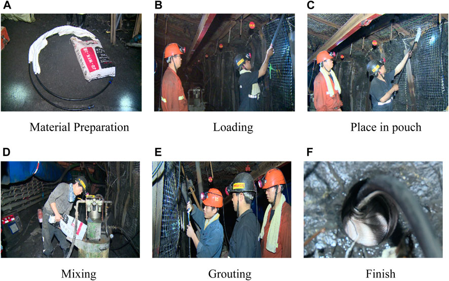
FIGURE 4. Flow chart of hole sealing process.
Through research and analysis, a ZBQ convenient pneumatic grouting pump was selected, including a grouting pump, pneumatic agitator, mixing barrel and other parts. The grouting pump uses compressed air as the power source and fully automatic pneumatic agitation, which is easy to operate and can effectively reduce the labor intensity of underground workers. When cleaning, you only need to open the mixing device and add water to prevent the quick-setting cement from blocking the air pump. The equipment has good versatility, and can be used in flammable and explosive environments and withstand regular temperature and humidity changes. The technical parameters of the grouting pump are shown in Table 3.

TABLE 3. Technical parameters of slurry injection pump.
During the hole sealing operation, the following operation steps need to be strictly followed, as shown in Figures 4A–F.
1) Begin the slurry sealing operation after the charge in the borehole is completed. 2) Use the water pipe to flush out the slurry pump, mixing barrel and connecting pipeline, and test the mixer and slurry pump; 3) Add water to the mixing barrel, and while mixing the water, slowly add the hole sealing material to prevent jamming the mixer until the water-cement ratio reaches the specified ratio (1:1); 4) When grouting, first put the bladder bag into the blast hole, and then connect it to the grouting pump through the tail quick connect. Turn on the grouting pump; grouting speed should be slow, and grout while stirring slowly. When there is water leaching out of the bag, it proves the smoothness of the pipeline; in the process of grouting, when the grouting pump works at a normal, even speed, the grouting pump can be adjusted to a high speed for grouting; when the grouting pump makes a dull sound, the pressure gauge reading obviously increases to 2 MPa and the grouting pump shows that no slurry can be injected, and the grouting pump is shut down. At this time, the grouting pipe is bent and tied with a tie to prevent the slurry from flowing back; 5) When switching to another pre-fractured hole for grouting, the action should be fast to prevent the slurry in the pipeline from solidifying and causing the pipeline to be blocked; for switching grouting between different pre-fractured holes, only special scissors should be used to cut the grouting pipe. Then it should be connected with the quick connect of another pipe until all pre-fractured holes are grouted; 6) After grouting is completed, the slurry suction pipe must be sucked with water, the slurry drain valve must be opened, and the whole pipeline and pump body must be flushed clean by running at full speed for about 2 min; 7) Evacuate the personnel and pull up the safety warning line; 8) The waiting time is 1 h before the cannon release work can be carried out.
The depth of the blast hole used in the mine is 10 m, the diameter of the hole is 55mm, the distance between the holes is 0.5 m ± 0.75 m, and the angle of the hole is 75°∼90° offset from the horizontal line upwards (the coal wall side of the working face).
When assembling the charge rolls using the polyenergy tube, the secondary hydrogel explosive and the gun head are loaded into the polyenergy tube, and the polyenergy tube is connected with the casing. Pre-cracking blasting is carried out within the peak area of the over-supporting stress in the over-supporting working face of the roof-cutting hole, and the charge of the poly-energy charge roll is 1.5 kg/hole, with one charge and one release. A special cable should be used as the discharge bus, and no more than 10 blasting holes at a time should be discharged. The length of each poly energy tube is no more than 1.5 m, and 1 detonator is used.
The hole is sealed with a 0.4 m pouch and the length of the hole is 1.5 m. The charging structure is 2 + 1 + 2 + 1 + 1 + 1 + 2, using three sections of a 1.5 m long poly energy tube. The bottom of the poly-energy tube and the middle of the poly-energy tube are each loaded with 1 piece of explosive and 1 gun head, and the bottom polyenergy tube uses 1 gun head, and the end of the poly-energy tube is sealed with materials such as gun clay filled with sponge or clay in order to prevent the explosive from slipping the trust. Between the poly-energy tube, a special sleeve connection can be used in order to pre-vent poor fixation and fix the body of the tape. The structure is shown in Figure 5.
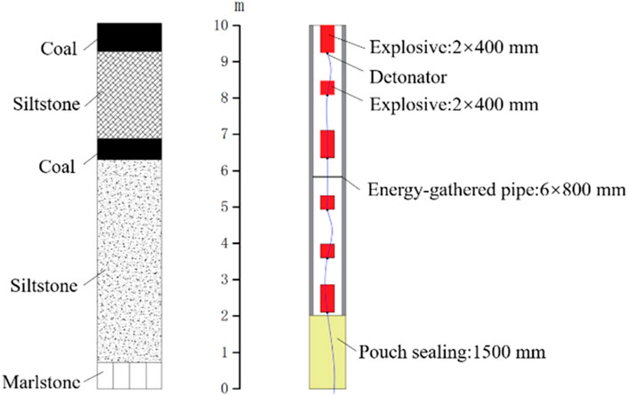
FIGURE 5. Section view of 11,503 W face.
Intra-hole fissure detection and imaging equipment adopts a mining intrinsically safe drilling imager, which penetrates the probe into the borehole, detects the inner wall of the borehole at different hole depths, takes pictures in real time, and then forms the fissure morphology map in the borehole to quantitatively analyze the blasting effect. After blasting, the observation hole or blast hole is imaged for in-hole detection to de-termine the optimal spacing between two adjacent holes.
Permission must be obtained for use of copyrighted material from other sources (including the web). Please note that it is compulsory to follow figure instructions.
In order to compare and study the blasting effect under different sealing process conditions, three blasting holes were used in the experiment using yellow mud sealing and pouch sealing methods, all with Φ55 mm hole diameter. First 1# and 3# drill holes were loaded, and 2# drill holes were observation holes, as shown in Table 4.
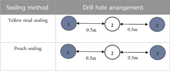
TABLE 4. Drill hole layout of different sealing materials.
All punching occurred when blasting with yellow mud seal hole. After blasting, the inside of the borehole was probed, as shown in Figure 6. As can be seen, the fissures in the inner wall of the borehole are irregular. There are about 6∼8 blast fissures clearly visible in cross section, and there are fissures distributed from 4.3 m at the hole mouth all the way to 8.6 m at the bottom of the hole. The results show that although the structure of the polygonal tube charge was used, the yellow mud seal hole there is a punching phenomenon, resulting in the explosive effect and the loss of the direction of the polygonal energy.
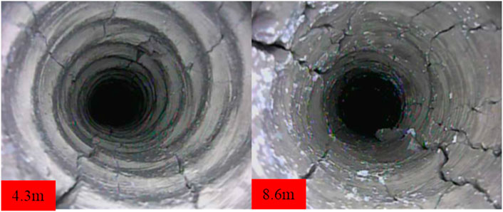
FIGURE 6. Fissure pattern of hole #2 of the yellow mud sealing blasting experiment.
The pouch sealing effect was good and none of the holes were punched. After blasting, the first detection was made in the #2 observation hole, as shown in Figure 7. There is an irregular distribution of fissures at 3.6 m, while there is a certain regularity in the direction of fissures from 3.6 m to 8.4 m. This phenomenon indicates that when the bladder pouch sealing method is used, the punching probability is small, and the energy generated by the explosion is well preserved in the blast hole, and the direction of energy gathering is obvious.
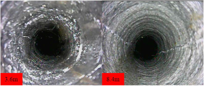
FIGURE 7. Fissure morphology of each hole in the pouch sealing blasting experiment.
According to the blasting experiments with different sealing processes, it can be seen that the use of the pouch sealing method can not only effectively achieve the sealing of holes but also shorten the sealing time to within 1 h and significantly improve the efficiency and reduce the labor intensity of workers. On this basis, experiments with different blast hole spacing were continued. Three blasting holes with Φ55 mm diameter were used for the experiment, and different sealing distances were achieved by using the pouch sealing method, with 1# and 3# holes being loaded and 2# holes being observation holes, as shown in Table 5.
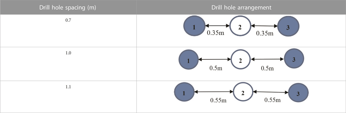
TABLE 5. Drill hole layout of different sealing methods.
After blasting at a hole spacing of 0.7 m, all blasting holes were not flushed, which indicates that the practice of using pouch sealing technology is feasible. The fissure patterns at different locations in the holes were obtained through in-hole probing of the observation holes, as shown in Figure 8. A small number of longitudinal fissures were found in observation hole #2, and most of the area remained intact. Through the experimental study, it was considered that the seam formation at the control hole can be achieved at the hole interval of 0.7 m, and the seam cutting distance of the current loading method is about 0.35∼0.4 m.
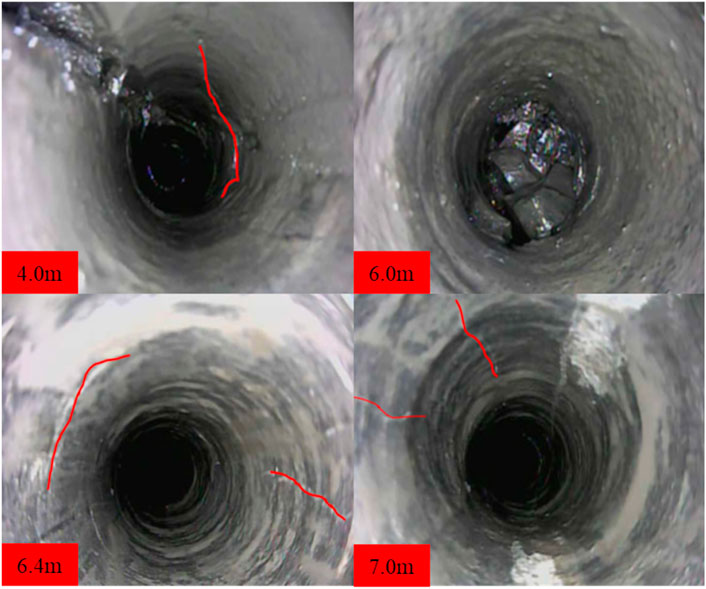
FIGURE 8. Morphology of Fissures in Boreholes Observed by Blasting when the Hole Spacing is 0.7 m.
After blasting at a hole spacing of 1m, the blast holes were not flushed, and the sealing effect was good. The #2 observation hole was probed and the burst fissure pattern was obtained, as shown in Figure 9. As shown from 3.8 m to the bottom of the hole, there is a more obvious burst fissure, with a total length of about 7 m. The bottom area of the hole present rock fragmentation phenomenon, and the form of axial cutting of the hole is more obvious. After measurement, the distance that can be cut when blasting reached 0.5 m. Compared to blasting holes with a spacing of 0.7 m, the cutting length increased by 43%
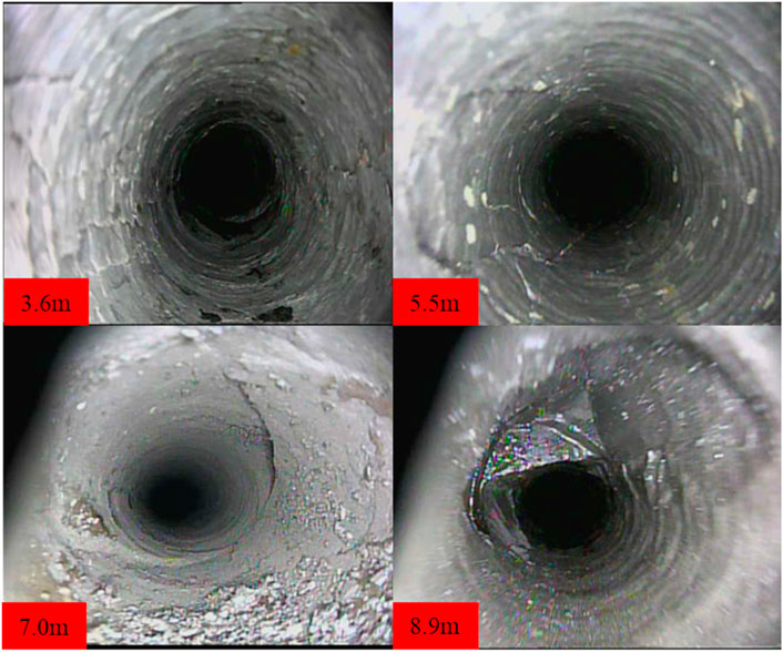
FIGURE 9. Hole spacing 1 m blasting experiment #2 drill hole blast fissure morphology.
After blasting at a hole spacing of 1.1m, a mesh fissure appeared at the front of the hole, and the fissure appeared within 1 m of the hole opening and within 3 m of the hole bottom, with a fissure length of about 3m, as shown in Figure 10. Compared with the 1 m hole spacing, although the top plate was also cut at this time, the effect was not as good as that at the 1 m hole spacing. The cutting distance during blasting can reach 0.4 m. The cutting length was reduced by 25% compared to the length of blasting holes with a spacing of 1 m.
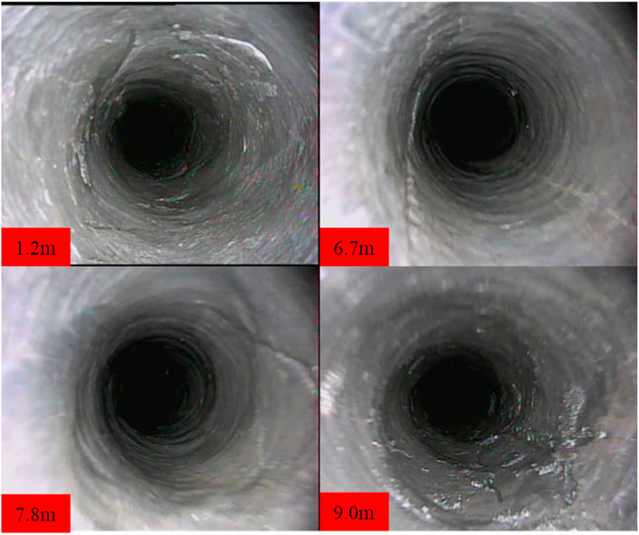
FIGURE 10. Blasting experiments with 1.1 m hole spacing in 2# drill hole blast fissure pattern.
Through field experiments, it can be found that after blasting with different hole spacing, the fissure is clearest and the blasting effect is best when the hole spacing is 1m, so a hole spacing of 1 m is chosen for blasting.
Using the laser distance meter, we measured the bottom drum of the roadway and the displacement data of the two gangs. With the continuous advancement of the working face, the pressure of the roof plate at each measurement point of the field test was gradually released. In order to avoid the influence of time on the measurement results, three field data measurements were carried out, take the average of three measurements. Each measurement wsa made at a time interval of 10d, with the last measurement being carried out when the roof pressure was released for 1 month. At this time the deformation of the roadway and surrounding rock gradually stabilized.
In order to analyze the bottom drum and the deformation law of the two gangs in the top-cutting stay area, the bottom drum and the displacement of the two gangs in the top-cutting section of the 11,503 W trackway were measured and analyzed. The depth of the pre-cracking blast hole was mainly 10 m, the distance between fixed measuring points was 25 m from the initial cutting hole position to the current working face, the area of the pouch clay sealing hole accounted for 150m, the area of the yellow mud sealing hole accounted for 150m, and the total length is 300 m. The specific measuring points are shown in Figure 11.
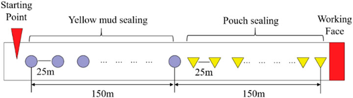
FIGURE 11. Schematic diagram of measurement point location.
At the end of the test, we collected the amount of bottom drum from the two gang displacements, as shown in Figures 12, 13. It can be seen that, in the yellow mud sealing stage, with the passage of time, the pressure release of the top plate is basically complete and the deformation of the roadway does not change much. The bottom drum volume of the last three tests were 1.17 m, 1.23 m, and 1.25 m, respectively, and, on average, the amount of floor heave increased by 5% and 1.6%, respectively. The displacement of the two gangs is 0.45 m, 0.50 m, and 0.56 m, respectively, on average, the displacement of the two sides increased by 11% and 12%, respectively. The bottom drum volume of the third test is 0.08 m higher than the bottom drum volume of the first test, and the displacement of the two gangs is 0.11 m higher. In the vicinity of 125 m from the starting point, the deformation of the roadway is smaller, and the displacement of the two gangs is almost 0.
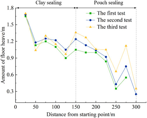
FIGURE 12. Diagram of change of floor heave.
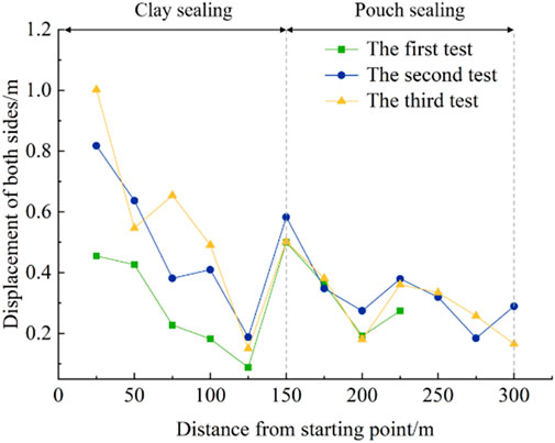
FIGURE 13. Diagram of change of floor heave.
In the pouch sealing stage, the test data of the bottom drum volume and displacement volume of both gangs show a significant reduction compared with the gun clay sealing stage, as shown in Figures 12, 13. The bottom drum volumes of the last three tests were 0.62 m, 0.75 m, and 0.92 m, on average, and considering the recent undercover work, the bottom drum volume of the third test was small, and the actual average bottom drum was about 1 m; the displacement volumes of the two gangs were 0.14 m, 0.30 m and 0.28 m on average; with the passage of time, the bottom drum volume of the pouch sealing stage had increased more obviously, Finally, in the third test, the bottom drum volume increased by 0.30 m compared with the initial test bottom drum volume, while the displacement volume of the two gangs increased by 0.14 m.
From the analysis of the data of the last three tests, it can be obtained that the bottom drum volume of the pouch sealing stage is reduced by 47%, 39%, and 26%, respectively compared with the yellow mud sealing stage, while the displacement of the two gangs is reduced by 68%, 40%, and 50%, respectively, compared with the yellow mud sealing stage. It is concluded that the bottom drum volume of the pouch sealing stage is reduced by 37% compared with the yellow mud sealing stage, and the displacement of the two gangs is reduced by 53% compared with the yellow mud sealing stage, so the pouch sealing effect is remarkable.
On-site industrial experiments show that the use of this technology can be realized within a short period of time to effectively block the blasting drill holes, shortened by more than 50% compared with the existing technology, the amount of drilling work compared to the current drilling layout to reduce more than 20%, the total amount of explosives used to reduce the more than 50%; the implementation of the project has significantly improved the efficiency of cutting the top of the alley to stay in the blasting.
In this study, a new hole sealing technique is proposed to study the effect of different hole spacing on fissure expansion through directional fissuring by polyenergy blasting. The deformation law of the cut-top stay section is also analyzed and the following conclusions are drawn.
(1) Different water-cement ratio materials with a reduced moisture ratio increase, the rate of temperature increase, and the rate of temperature decrease also decreases; all specimens reached the highest value at about 30 min, of which the specimen with the smallest water-cement ratio had the highest peak temperature, and the peak temperature reached 49 °C at 0.3:1; with the increase in water-cement ratio, the time of loss of flow and gelation phenomenon was gradually delayed, and the loss of flow and gelation time between the appearance of loss of flow and gelling became longer. When the water-cement ratio was fixed, the uniaxial compressive strength increased with the increase in time. When the time was the same, the uniaxial compressive strength of the test block gradually increased with the decrease in water-cement ratio.
(2) When the hole spacing is 0.7 m, a small number of longitudinal fissures are found in the hole, and most of the area is still relatively intact; when the hole spacing is 1m, there are obvious explosive fissures in the hole, with a total length of about 7 m and rock fragmentation appears in the bottom area of the hole; when the hole spacing is 1.1 m, there are net-like fissures in the front of the hole, and the fissures appear within 1 m of the hole mouth and 3 m of the bottom of the hole, and the effect is not as good as when the hole spacing is 1 m.
(3) For the bottom drum and two gang deformation law in the area of the cut-top stay lane, it can be seen throughout the tests that the bottom drum amount and two gang dis-placements in the pouch sealing stage are reduced to 36% and 31%,respectively, compared with the yellow mud clay sealing stage, the probability of punching a hole in the pouch sealing hole is small and the direction of the gathering energy is obvious, Thus it can be seen that the effect produced by the pouch sealing hole is better than the yellow mud sealing hole.
On site industrial experiments have shown that the use of this technology can achieve the effective sealing of blasting boreholes in a short period of time (30 min), which is more than 50% shorter than existing technologies. The drilling quantity is reduced by more than 20% compared to the current drilling arrangement method, and the total amount of explosives used is reduced by more than 50%. The implementation of the project has significantly improved the efficiency of roof cutting and roadway retaining blasting.
The datasets presented in this study can be found in online repositories. The names of the repository/repositories and accession number(s) can be found in the article/Supplementary material.
CW: Writing–original draft, Writing–review and editing. ZY: Formal Analysis, Writing–review and editing, Data curation. YM: Writing–review and editing, Funding acquisition. DC: Writing–review and editing, Validation. DW: Writing–review and editing, Formal Analysis. AZ: Writing–review and editing, Methodology.
The author(s) declare financial support was received for the research, authorship, and/or publication of this article. The authors are grateful to the financial support from the National Natural Science Foundation of China (52174161 and U21A20110).
Authors DC and DW were employed by Shandong Huakun Geological Engineering Co. Ltd.
The remaining authors declare that the research was conducted in the absence of any commercial or financial relationships that could be construed as a potential conflict of interest.
All claims expressed in this article are solely those of the authors and do not necessarily represent those of their affiliated organizations, or those of the publisher, the editors and the reviewers. Any product that may be evaluated in this article, or claim that may be made by its manufacturer, is not guaranteed or endorsed by the publisher.
Chen, B. B. (2019). Study on the mechanism of rock fracture increase by water-filled pressurized solid-liquid coupled blasting in borehole. China: China University of Mining and Technology.
Chen, S. J., Feng, F., Wang, Y. J., Huang, W. P., and Zhao, X. D. (2020). Tunnel failure in hard rock with multiple weak planes due to excavation unloading of in-situ stress. J. Central South Univ. 27, 2864–2882. doi:10.1007/s11771-020-4515-7
Feng, F., Chen, S. J., Wang, Y. J., Huang, W., and Han, Z. (2021). Cracking mechanism and strength criteria evaluation of granite affected by intermediate principal stresses subjected to unloading stress state. Int. J. Rock Mech. Min. Sci. 143, 104783. doi:10.1016/j.ijrmms.2021.104783
Foderà, G. M., Voza, A., Tinti, F., and Boldini, D. (2020). Factors influencing overbreak volumes in drill-and-blast tunnel excavation. A statistical analysis applied to the case study of the Brenner Base Tunnel – BBT. Tunn. Undergr. Space Technol. 105, 103475. doi:10.1016/j.tust.2020.103475
Gao, C., Kong, X. Z., Fang, Q., Hong, J., and Wang, Y. (2022). Numerical investigation on free air blast loads generated from center-initiated cylindrical charges with varied aspect ratio in arbitrary orientation. Def. Technol. 18 (9), 1662–1678. doi:10.1016/j.dt.2021.07.013
Gao, K., Liu, Z. G., and Liu, J. (2012). Research on soft coal abatement and rapid road formation technology in Shimen Jie structure. Chin. J. Coal Sci. Technol. 40 (11), 66–68. Avaliable at: http://www.cnki.net/kcms/detail/11.2402.TD.20121116.1108.017.Html.
Ge, Z. L., Mei, X. D., Lu, Y. Y., Tang, J., and Xia, B. (2014). Optimization and application of sealing material and sealing length for hydraulic fracturing borehole in underground coal mines. Arab. J. Geosci. 8 (6), 3477–3490. doi:10.1007/s12517-014-1488-6
Gong, H. P., Li, J. W., and Chen, B. B. (2013). Study on overburden structure and stability of surrounding rocks in close coal seam group mining. Chin. J. Coal Min. 18 (5), 90–92. doi:10.13532/j.cnki.cn11-3677/td.2013.05.028
Guo, S., Zhang, Q., He, M. C., Wang, J., Liu, J., Ming, C., et al. (2022). Numerical investigation on rock fracture induced by a new directional rock-breaking technology. Eng. Fract. Mech. 268, 108473. doi:10.1016/j.engfracmech.2022.108473
Guo, X., Xue, S., Zheng, C. S., and Li, Y. B. (2021). Experimental research on performance of new gas drainage borehole sealing material with high fluidity. Adv. Mater. Sci. Eng. 2021, 1–12. doi:10.1155/2021/6645425
Hao, J., Chen, A. F., Li, X. L., Bian, H., Zhou, G., Wu, Z., et al. (2022). Analysis of surrounding rock control technology and its application on a dynamic pressure roadway in a thick coal seam. Energies 15 (12), 9040. doi:10.3390/en15239040
Huang, W. Y., Yan, S. L., and Liu, Z. G. (2012). Research and application of hydrogel pillar for coal mine gas extraction in deep hole blasting of coal seam. Chin. J. Coal 37 (3), 472–476. doi:10.13225/j.cnki.jccs.2012.03.029
Li, X. H., Zhu, Z. M., Wang, M., Xiao, D., Shu, Y., and Deng, S. (2021). Fracture mechanism of rock around a tunnel-shaped cavity with interconnected cracks under blasting stress waves. Int. J. Impact Eng. 157, 103999. doi:10.1016/j.ijimpeng.2021.103999
Li, X. S., Si, K., He, T., and Li, C. Y. (2022). Dynamic effect of shaped charge blasting and its application in coal seam permeability enhancement. ACS Omega 7 (29), 25353–25365. doi:10.1021/acsomega.2c02329
Liu, J., and Liu, Z. G. (2012). Study on the application of deep hole pre-cracking blasting technology in wellbore coal uncovering. Chin. J. Coal Sci. Technol. 40 (2), 19–21. Avaliable at: http://www.cnki.net/kcms/detail/11.2402.TD.20120215.1128.006.Html.
Liu, J., Liu, Z. G., and Gao, K. (2016). Experimental study on the fracture propagation characteristics of coal seam under different loading modes. Chin. J. Rock Mech. Eng. 35 (4), 735–942.
Ma, T. H., Li, F. J., Yang, Y. H., and Li, L. M. (2022). Study on energy evolution and crack propagation of rock mass under single hole uncoupled charge blasting. Appl. Eng. Sci. 11, 100112. doi:10.1016/j.apples.2022.100112
Meng, N. K., Chen, Y., Bai, J. B., Wang, X., Wu, W., and Wu, B. (2020). Numerical simulation of directional fracturing by shaped charge blasting. Energy Sci. Eng. 8 (05), 1824–1839. doi:10.1002/ese3.635
Wang, G., Liu, H., Luo, J. H., Xu, H., Liu, Q., Zhou, X., et al. (2018). Preparation of a new borehole sealing material of coal seam water infusion. Adv. Mater. Sci. Eng. 2018, 1–7. doi:10.1155/2018/5924614
Wang, L. C., Xue, Y., Cao, Z. Z., Kong, H., Han, J., and Zhang, Z. (2023). Experimental study on mode I fracture characteristics of granite after low temperature cooling with liquid nitrogen. Water 15 (19), 3442. doi:10.3390/w15193442
Wang, Y. A., and Ren, Z. M. (2018). Gohanshan mine directional pre-cracking blasting cutting the top and unloading pressure along the empty stay technology. Chin. J. Coal Sci. Technol. 46 (10), 130–135. doi:10.13199/j.cnki.jccs.2018.10.020
Wu, B., Xu, S. X., Meng, G. W., and Cui, Y. Z. (2022). Research on structural parameter optimization of elliptical bipolar linear shaped charge based on machine learning. Heliyon 8 (10), 10992. doi:10.1016/j.heliyon.2022.e10992
Yang, G., Yang, X. J., Huang, R. F., Kang, X., Zhang, J., Hou, S., et al. (2023a). Failure mechanism and bulking characteristic of goaf roof in no-pillar mining by roof cutting technology. Eng. Fail. Anal. 150, 107320. doi:10.1016/j.engfailanal.2023.107320
Yang, R. S., and Su, H. (2019). Experimental study of crack expansion with pre-cracks under blast loading. Chin. J. coal 44 (02), 482–489. doi:10.13225/j.cnki.Jccs.2018.0110
Yang, Y. K., Gao, P. P., Zhang, C., and Wang, C. L. (2023b). Numerical investigation of the influence of roof-cutting parameters on the stability of top coal gob-side entry retaining by roof pre-fracturing in ultra-thick coal seam. Energies 16 (12), 4788. doi:10.3390/en16124788
Yin, Y., Sun, Q., Zou, B. P., and Mu, Q. Y. (2021). Numerical study on an innovative shaped charge approach of rock blasting and the timing sequence effect in microsecond magnitude. Rock Mech. Rock Eng. 54 (09), 4523–4542. doi:10.1007/s00603-021-02516-w
Zhang, J. G., Zhou, Y. J., Zhou, X., Wang, M., Liu, S., Yang, Z., et al. (2023). The preparation of active support-based sealing material and sealing effect analysis. Appl. Sci. 13 (14), 8338. doi:10.3390/app13148338
Zhang, Q., He, M. C., Wang, J., Guo, S., Guo, Z., Liu, X., et al. (2020a). Instantaneous expansion with a single fracture: a new directional rock-breaking technology for roof cutting. Int. J. Rock Mech. Min. Sci. 132, 104399. doi:10.1016/j.ijrmms.2020.104399
Zhang, S. C., Li, Y. Y., Shen, B. T., Sun, X. Z., and Gao, L. Q. (2019). Effective evaluation of pressure relief drilling for reducing rock bursts and its application in underground coal mines. Int. J. Rock Mech. Min. Sci. 114, 7–16. doi:10.1016/j.ijrmms.2018.12.010
Keywords: roof cutting, pouch sealing technology, hole spacing, roadway deformation, poly-energy directional blasting
Citation: Wang C, Yin Z, Ma Y, Chen D, Wang D and Zhao A (2023) Optimization of hole spacing for cut-top blasting based on new hole-sealing technology. Front. Earth Sci. 11:1327074. doi: 10.3389/feart.2023.1327074
Received: 24 October 2023; Accepted: 11 December 2023;
Published: 29 December 2023.
Edited by:
Yi Xue, Xi’an University of Technology, ChinaReviewed by:
Junjun Feng, Anhui University of Technology, ChinaCopyright © 2023 Wang, Yin, Ma, Chen, Wang and Zhao. This is an open-access article distributed under the terms of the Creative Commons Attribution License (CC BY). The use, distribution or reproduction in other forums is permitted, provided the original author(s) and the copyright owner(s) are credited and that the original publication in this journal is cited, in accordance with accepted academic practice. No use, distribution or reproduction is permitted which does not comply with these terms.
*Correspondence: Yankun Ma, bWF5YW5rdW4yMDIxMDgyOEAxNjMuY29t
Disclaimer: All claims expressed in this article are solely those of the authors and do not necessarily represent those of their affiliated organizations, or those of the publisher, the editors and the reviewers. Any product that may be evaluated in this article or claim that may be made by its manufacturer is not guaranteed or endorsed by the publisher.
Research integrity at Frontiers
Learn more about the work of our research integrity team to safeguard the quality of each article we publish.