 Yongjie Yang
 Lingren Meng
 Lei Yuan
- State Key Laboratory of Strata Intelligent Control and Green Mining Co-Founded by Shandong Province and the Ministry of Science and Technology, Shandong University of Science and Technology, Qingdao, China
To investigate the overburden movement and the side abutment pressure distribution concerning the variation in deep mines with varying coal seam thickness, this study focused on the No. 72 mining area of Tianchen Coal Mine and obtained the following results: Variations in coal seam thickness within a stope lead to increased immediate roof thickness. When the coal seam thickness is 8 m, the maximum immediate roof thickness reaches 18 m. The roof is composed of a “Combined short cantilever-Voussoir beam” structure. Displacement curves of overburden in coal seam thickness-varying stopes exhibit asymmetry, with the overburden closer to the coal seam being more asymmetric. After post-goaf stabilization, the peak side abutment pressure decreases with increasing coal seam thickness and shifts deeper into the coal wall. Concurrently, the ultimate equilibrium area width expands. With an increase in coal seam thickness from 4 m to 8 m, the peak side abutment pressures decreased from 44.98 MPa to 41.04 MPa. The peak position shifted from a distance of 9 m from the coal wall to 14 m, while the stress-relaxation area expanded from 3 m to 5 m. This research provides essential insights for safe and efficient mining in similar conditions.
1 Introduction
Coal thickness variation zones, a distinctive and widely prevalent geological phenomenon, primarily result from geological factors such as folding structures, fault formations, magma intrusions, and sedimentary environments (Li et al., 2009). When excavating coal seams with variable thickness, the potential for rockbursts exists due to stress concentration and the rapid increase in elastic strain energy, thereby potentially leading to catastrophic accidents. Song (1988) and Xie (2020), through on-site data analysis, determined that 45.5% of impact ground pressure disasters occurred in the variable coal seam thickness area at Sichuan Tianchi Coal Mine, while 64% of power disaster accidents at Xintai Coalfield also happened in the variable coal seam thickness area. Therefore, it is imperative to study the movement of the overburden and the distribution of the side abutment pressure variable coal seam thickness area. This will provide theoretical guidance for monitoring the effects of ground pressure and preventing pressure relief.
In recent years, scholars both domestically and internationally have extensively researched the movements of overburden and related phenomena, resulting in certain findings. Song and Jiang (1996) introduced the “Cantilever Beam Hypothesis” which defines the concepts of immediate and basic roof. Song et al. (2019) offer theoretical formulas to calculate their thickness, advancing the research from traditional mining pressure theories to specific rock layer quantitative studies. Qian et al. (2010) established a structural model of “Voussoir Beam Hypothesis” in the overburden, and further proposed the theory of “Key Stratum” based on it. Xu and Qian (2000a) proposed the displacement equation for the “block beam” structure. Xu and Qian (2000b) further refining the “Key stratum” theory. Xie and Wang (2010) conducted research on the effect of coal seam thickness variations on the movement patterns of overburden in fully mechanized caving face. It was found that the amount of coal seam and overburden destruction is non-linearly proportional to the thickness of the coal seam being mined. Liu et al. (2015) conducted research on the displacement patterns of overburden with varying disintegration ratios in deeply buried inclined coal seams during the application of the full-mechanized caving mining method. The findings indicated that the displacement pattern of inclined coal seams fundamentally differs from that of horizontal coal seams. Yu et al. (2020) investigated the relationship between the movement patterns of overburden formations and the spatial and temporal magnitude of the coal volume mined. Zhang et al. (2022) conducted a numerical simulation to examine the patterns of fissure development, displacement distribution, and abutment pressure variation above the goaf during the mining stage of the working face.
Wang et al. (2015) obtained the complete process characteristics of the side abutment pressure evolution in goaf and the movement of coal and rock through on-site survey methods. Xu et al. (2014) conducted a study on the distribution of side abutment pressure in the fully mechanized caving face of extremely thick coal seams using a similar material simulation test method and determined the peak value and influence range of the side abutment pressure. Gao et al. (2022) comprehensively utilized theoretical calculations, on-site monitoring, and other methods to study the side abutment pressure distribution of an ultra-thick coal seam fully mechanized mining face, determining the appropriate coal pillar. Ren et al. (2014) utilized a numerical simulation method to explore stress distribution and the distribution of elastic strain energy under varying coal seam thickness conditions. Building upon the mechanical model of coal-rock assemblage, Zhao et al. (2016) conducted an analysis of the mechanical mechanisms of impact ground pressure in coal seams within areas characterized by varying coal thickness. Wang et al. (2017) utilized numerical simulations to examine the distribution and evolution patterns of advanced abutment pressure and elastic strain energy in areas with localized variations in coal seam thickness within a 10-m range. Liu and Liang (2018) conducted an extensive investigation into the stress distribution laws within the area of coal thickness variation. Shang et al. (2020) analyzed the characteristics of the “strip” distribution of rock burst during the setup entry formation process and provided insights into the impact of coal thickness changes on initial stress and mining-induced stress, considering the on-site conditions. Additionally, through theoretical analysis, Liu (2021) derived equations describing the variations in stress and energy resulting from changes in coal seam thickness.
Currently, there has been notable progress in researching overburden movement and the distribution of side abutment pressure in quarries with stable coal seam thickness. However, there is a lack of research on overburden movement and side abutment pressure distribution in quarries with variable coal seam thickness. Furthermore, existing research on coal seam thickness variation areas has been limited in scope, with relatively little focus on extensive coal seam thickness variation areas. As a response, this study is set against the geological and mining conditions of the No. 72 mining area of Tian Chen Coal Mine. It employs mine pressure theory and numerical simulation technology to analyze overburden movement and side abutment pressure in large-scale, deep-burial coal thickness variation mining areas. The aim is to provide technical guidance and a scientific foundation for the safe and efficient mining of the upcoming working face in the No. 72 mining area and other mines facing similar coal thickness variation conditions.
2 The engineering background
In the No. 72 mining area of Tianchen Coal Mine, coal seam No. Three is the target for extraction. The southern part of the mine is in close proximity to the washout zone in coal seam, resulting in thinner coal seams in this region. Conversely, in other areas of the coal seams, conditions remain relatively stable. Notably, these coal seams contain local intercalated gangue layers, ranging in thickness from 0.06 m to 0.8 m. This geological complexity adds an additional layer of challenge to mining operations, although the region remains unaffected by intrusive igneous rocks. The No. 7202 fully mechanized caving mining face is arranged along the strike of the coal seam. The track roadway extends over a length of 813 m. The average depth of the coal seam is −760 m. The coal seam thickness exhibits variability, with a minimum thickness of 2.1 m and a maximum thickness of 8 m. The seam inclination ranges between 6° and 18°. It is worth noting that the setup entry is situated near the washout zone in coal seam, Resulting in a decrease in the thickness of coal in this particular region. In contrast, the middle and outer segments of the working face boast thicker coal seams. The coal seam thickness contour lines are depicted in Figure 1. The coal seam thickness gradually increases from 2 m at the start of the excavation face, continuously expanding along the roadway direction. Eventually, at a distance of 350 m from the starting point, the coal seam thickness reaches 8 m and remains consistently at 8 m beyond this 350-m mark. The length of the coal seam thickness variation zone extends approximately 350 m.

FIGURE 1. Layout of No. 7202 working face.
The roof of the No. 7202 fully mechanized caving mining face is comprised of medium-fine sandstone with a thickness ranging from 9 m to 18 m, averaging at 14 m. It possesses a high degree of hardness, with a rock strength (f-value) falling within the range of 8–10. Beneath the working face, the immediate floor consists of sandy mudstone, with a thickness averages around 17.2 m. This with a rock strength (f-value) ranging from 4 to 6. The simplified geologic column is shown in Figure 2.
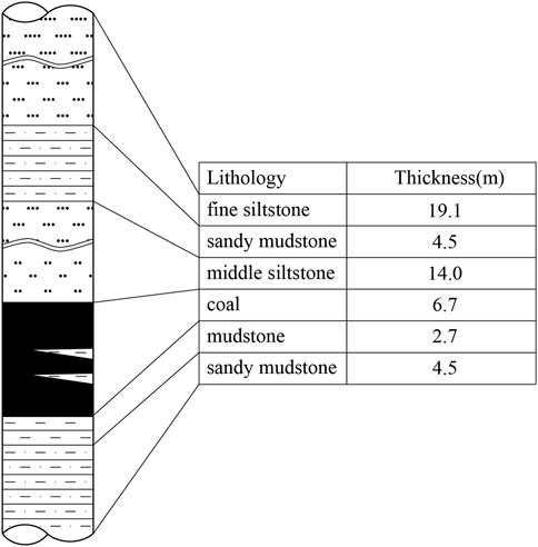
FIGURE 2. Simplified geological column.
3 Movement law of overburden in coal seam thickness variation stope
3.1 Theoretical analysis of overburden movement
The No.7202 fully mechanized caving mining face is located beneath a 14-m-thick roof consisting of medium-fine sandstone. To reduce the intense ground pressure experienced in the working face, a decision has been made to implement presplitting blasting techniques, drawing from the knowledge gained in neighboring mining areas. This approach is intended to effectively weaken the overburden.
After presplitting blasting, the roof of the working face develops more fractures, disrupting its integrity. In the early mining stages, when the coal seam is thin and there’s no remaining roof coal, the compromised immediate roof fills the goaf, creating limited space below the basic roof. This causes the basic roof to bend and separate from the overburden.
As the working face advances, the coal seam thickness exceeds the mining height. Initially, the goaf is filled with top coal and the immediate roof. Continuous release of collapsed top coal creates new voids in the goaf. Larger roof rocks undergo subsidence and fragmentation. The uncollapsed roof in the front and collapsed gangue in the rear mutually support each other, forming a semi-arch structure (Nan and Wang, 2022).
In later mining stages, as the coal seam thickens, the goaf space expands. Ongoing collapse of the immediate roof increases the space between the basic roof and collapsed gangue, raising the subsidence height of the basic roof.
3.2 Presplitting blasting program
To meet blasting induced roof fracturing requirements, a plan was devised for deep-hole presplitting blasting in roadways and the setup entry to presplitting the overburden. Before initial mining, full-roadway inclined deep-hole presplitting blasting is applied near the tow ribs of the working face.
To ensure the integrity of the roof strata is effectively compromised, allowing for the development of roof fractures and maintaining a safe production environment, a blasting plan is implemented in the haulage roadway (track roadway). The blasting boreholes have a diameter of φ75 mm and a depth of 40 m, and they are drilled at three different angles. When the angle is 66°, the inclined length of the borehole is approximately 44 m (40 m/sin66°); at 55°, it is roughly 49 m (40 m/sin55°); and at 45°, it measures around 57 m (40 m/sin45°).
For the blasting, cartridge-type explosives with specifications φ63 mm×1000 mm and a density of 3.5 kg/m are used. When the borehole depth is 44 m, the explosive loading length is 23 m, and the stemming length is 21 m or not less than one-third of the borehole length. This results in a single-hole explosive loading quantity of 80.5 Kg. For boreholes with a depth of 49 m, the explosive loading length is 25 m, and the stemming length is 24 m or not less than one-third of the borehole length, yielding a single-hole explosive loading quantity of 87.5 Kg. When the borehole depth is 57 m, the explosive loading length extends to 28 m, with a stemming length of 29 m or not less than one-third of the borehole length, resulting in a single-hole explosive loading quantity of 98 Kg. Please refer to Figure 3 and Figure 4 for the cross-sectional profiles of the blasting boreholes.
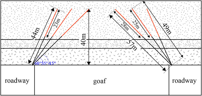
FIGURE 3. Schematic cross-section of pre-split blasting holes.
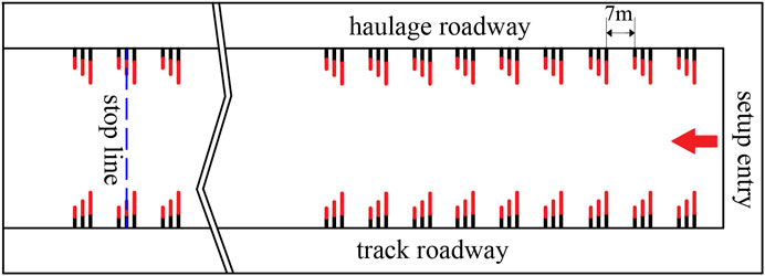
FIGURE 4. Schematic plan view of pre-split blasting holes.
Plans and sections of the blast holes are shown below in Figure 3 and Figure 4, with the red holes are indicative of the blasting holes in the strike direction in Figure 4.
3.3 Theoretical analysis of roof structure changes
3.3.1 Research on changes in the immediate roof structure of the stope
In the context of the No. 7202 working face, where coal seam thickness exhibits variability, the thickness of the top coal undergoes changes throughout the mining process. As a result, the law of variation in immediate roof thickness differs from that typically observed in conventional coal mining areas. Figure 5 presents the graphical representation of immediate roof thickness, and the expression is as follows:
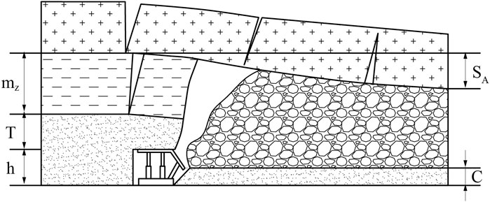
FIGURE 5. Immediate roof thickness calculation diagram.
In the equation, h represents mining height in meters (m), T represents thickness of top coal in meters (m), C represents residual coal thickness in meters (m), KA represents rock fragmentation coefficient, assumed to be 1.3 and SA represents subsidence of the basic roof at the contact with gangue in meters (m).
The thickness of the immediate roof was calculated to be about 5.3 m, 10.4 m and 19.7 m when the thickness of the coal seam was 2 m, 4 m and 8 m respectively.
3.3.2 Research on changes in the basic roof structure of the stope
The traditional definition of the basic roof is as follows: it is a thick and hard rock layer located directly above the immediate roof, which exerts a direct influence on the strata pressure. After the initial fracture of the basic roof, it will exist in the form of a “Voussoir beam” structure (Qian et al., 2010). Despite undergoing pre-split blasting, the roof retains a certain degree of strength due to its substantial thickness. Upon the collapse of the basic roof, it takes on an “Articulated rock beam” structure, which lacks long-term stability. As the mining height increases, the active area of the goaf roof expands, causing the “Articulated rock beam” structure to undergo a reverse break and rotation, ultimately forming a “Cantilever beam” structure. At this stage, the original basic roof transitions into the immediate roof, while the basic roof rock layer with the articulated structure migrates to higher strata (Yang, 2023).
The roof rock layers, from bottom to top, can be divided into the following sections: the lower immediate roof, which collapses as mining progresses; the upper immediate roof, forming a “Combined short cantilever beam” structure; and the basic roof, existing in the form of an “Articulated rock beam.” Therefore, during the process of fully mechanized mining, the upper roof layers form a structural combination known as “Combined short cantilever—articulated rock beam”, as depicted in Figure 6 (Yu et al., 2012; Yu, 2013).
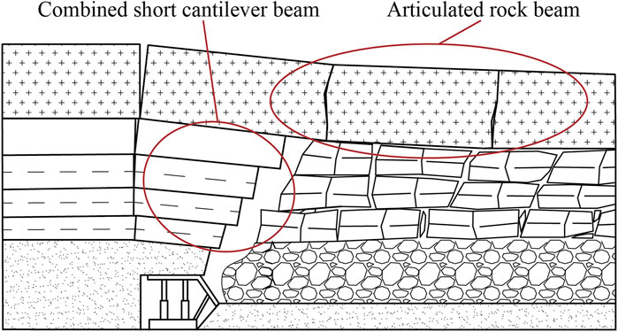
FIGURE 6. “Combined short cantilever - articulated rock beam” structural.
3.4 Numerical modelling of overburden movement
3.4.1 Modelling
In this chapter, UDEC numerical simulation software is employed to establish a model based on the actual geological conditions of the No.7202 working face. The simulation aims to depict the movement and changing laws of the overburden during the mining of this working face. The model’s dimensions are 750 m x 200 m, as illustrated in Figure 7. The Mohr-Coulomb constitutive model is utilized, and the mechanical parameters for each formation in the model are detailed in Table 1.
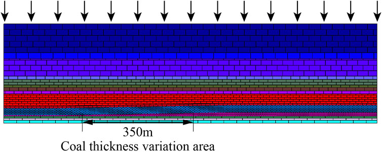
FIGURE 7. Numerical simulation model of UDEC.
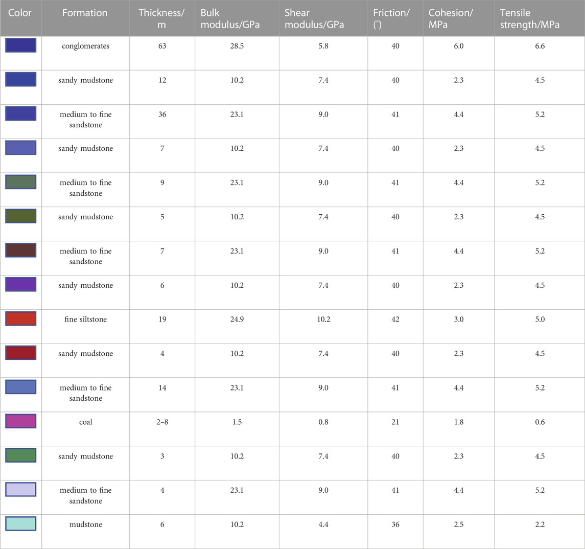
TABLE 1. Mechanical parameters of the roof and floor of the No.7202 working face.
Horizontal displacement constraints are applied to both boundaries of the model, while boundary displacement constraints are implemented at the bottom. A vertical load of 17 MPa is applied to the top boundary of the model to replicate the actual ground loads. To mitigate boundary effects during the simulation, 100-m-wide coal pillars are retained on both sides of the model.
In the UDEC simulation to analyze the stress state of the surrounding rock after blast decompression, the approach employed is as follows:
Initially, the simulation replicates normal excavation conditions. After achieving stable equilibrium through simulation, the material constants of the surrounding rock within the blast crushing area are adjusted to one-fifth (1/5) of their original values. Subsequently, the simulation is re-run with these modified material properties. The stress results obtained from this re-simulation represent the stress state of the surrounding rock after blast decompression (Zhou et al., 2005).
3.4.2 Analysis of simulation results
1) Study of the evolutionary law of overburden damage
After the establishment of the numerical simulation, practical coal mining experiments were carried out. These experiments yielded Figure 8 depicting the movement of overburden as the working face advanced over varying distances.
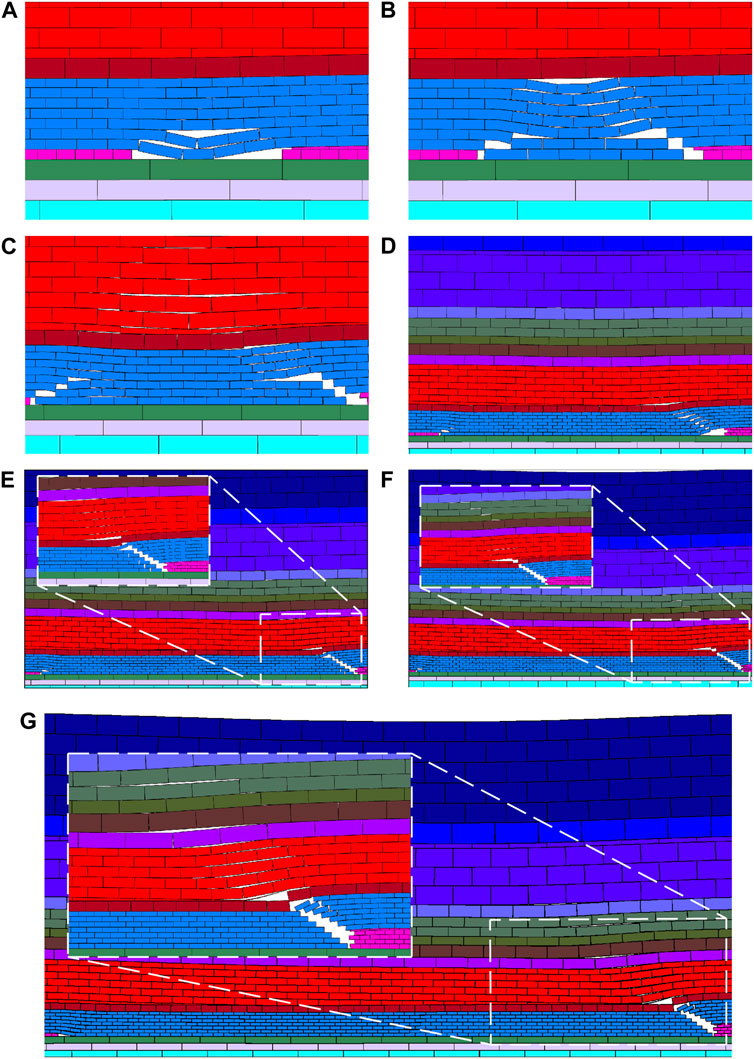
FIGURE 8. Damage evolution of overburden at different advance distances. (A) advance 30 m, (B) advance 45 m, (C) advance 90 m, (D) advance 180 m, (E) advance 240 m, (F) advance 300 m, (G) advance 380 m.
As the working face advanced to 30 m, stratification occurred within the medium-fine sandstone layers. The lower portion of these stratified rock layers served as the immediate roof of the goaf and had an approximate thickness of 4 m. The immediate roof reached its tensile strength limit, resulting in fractures and eventual collapse. Simultaneously, the upper portion of the stratified rock layers in the medium-fine sandstone developed fissures, leading to bending and subsidence.
As the working face advanced to 45 m, the immediate roof of the working face continued to experience fracturing and collapse. The upper portion of the stratified rock layers within the medium-fine sandstone, having already undergone bending and subsidence, eventually contacted the gangue formed by the fracture and collapse of the immediate roof, causing them to cease their movement.
As the working face advanced to 90 m, the coal seam thickness is 3.5 m, stratification became evident in the basic roof. The lower portion of the basic roof had a substantial exposed area, leading to fractures at the bottom of this lower portion. Due to the limited space beneath this lower portion of the basic roof and less room for rock beam slewing, a “Voussoir beam” structure emerged.
As the working face advanced to 180 m, the coal seam thickness is 5 m, the rear goaf area had become largely compacted. Periodic weighting interval intervals of 10–15 m. The medium-fine sandstone layers continued their gradual transformation into the immediate roof, resulting in the current immediate roof having an approximate thickness of 10 m. The lower immediate roof collapses as mining progresses, while the upper immediate roof forms a “Short cantilever beam” structure. The overburden above the basic roof experienced bending and subsidence, leading to the closure of fissures. As the mining thickness increased, the space beneath the basic roof gradually expanded.
As the working face advanced to 240 m, the coal seam thickness is 6 m, the mining thickness increased to 6 m. The medium-fine sandstone had essentially transformed into the immediate roof. The upper immediate roof, forming a “Short cantilever beam” structure, was severed at the coal wall, resulting in an increased height of immediate roof collapse. Above the direct roof, the sandy mudstone layers lacked adequate support from rocks or gangue due to the substantial space beneath, leading to their sliding instability and forming a “Combined cantilever beam” structure in conjunction with the overlying medium-fine sandstone rock layer. The basic roof experienced fracture and rotation, forming a “Voussoir beam” structure, with the fissures continuing to propagate upwards.
As the working face advanced to 300 m, the coal seam thickness is 7 m, the upper immediate roof, forming a “Short cantilever beam” structure, was severed at the coal wall. This results in an increase in the void space beneath the basic roof, and there is a greater downward displacement of the basic roof. However, the basic roof still maintains its “Voussoir beam” structure.
As the working face advanced to 380 m, the coal seam thickness is 8 m, and there is no further change both the thickness of the coal seam and the thickness of the immediate roof remained constant. The immediate roof consisted of medium-fine sandstone and sandy mudstone, measuring 18 m in thickness. The upper immediate roof forms a “combined short cantilever beam” structure, with the basic roof’s point of contact located above the compacted rubble pile, providing sufficient support from the overlying strata. At this stage, the upper immediate roof and the basic roof together create a “Combined short cantilever - Voussoir beam “structure.
2) Study of the evolutionary law of overburden transport
In the model, three measurement lines were placed, with each line featuring an evenly distributed set of 75 measurement points, spaced 10 m apart. These three measurement lines were situated at distances of 2 m, 18 m, and 30 m from the top of the coal seam. Figure 9 illustrates the evolution of overlying strata movement in the mining area at different advancement distances.
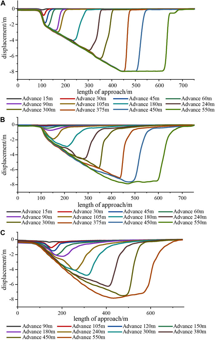
FIGURE 9. Plot of overburden transport history. (A) measurement line I, (B) measurement lines II, (C) measurement lines III.
From measurement line I, it is evident that the maximum subsidence of the immediate roof increases with the growth in mining thickness. Concurrently, the thickness of the immediate roof also augments as the working face progresses. The maximum subsidence of the immediate roof reaches 8 m, while its maximum thickness extends to 18 m. The first weighting interval of the working face is 30 m, and the periodic weighting interval is 15 m–20 m.
Analysis of measurement lines II and III reveals that the maximum subsidence of the basic roof escalates with the increase in mining thickness. As the working face advances, the asymmetry within the subsidence curve gradually intensifies. The principal transformation is observed in the rising slope of the subsidence curve near the coal wall side. Additionally, it becomes apparent that the closer the measurement line is to the coal seam, the greater the degree of asymmetry observed.
4 Distribution law of side abutment pressure in coal seam thickness variation stope
4.1 Theoretical analysis of side abutment pressure
After the mining operation, the original rock stress within the mining area undergoes changes. The gravitational distribution of the overburden above the goaf is redistributed to the surrounding areas. As a result, the stress distribution around the stope is altered, leading to the formation of abutment pressure areas around the stope, as depicted in Figure 10.

FIGURE 10. Stress distribution around the working face.
One represents the front abutment pressure in front of the working face, 2 and 3 represent the side abutment pressures on the sides of the working face, and 4 represents the coal body abutment pressure on the side of the working face where the setup entry is located in the rear of the working face.
The analysis considers the coal body at the edge, which is within the limit strength range, as a whole. The coal body is regarded as a continuous and homogeneous material, with its yielding following the Mohr-Coulomb criterion, resulting in shear failure. A mechanical model is established based on the principles of limit equilibrium within the plastic area, as illustrated in Figure 11.
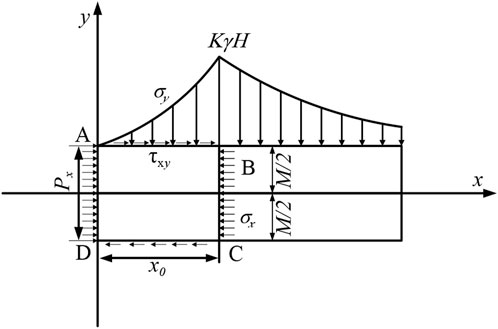
FIGURE 11. Lateral coal body stress limit equilibrium area.
According to the equilibrium differential equations, it can be derived Based on the equilibrium differential equation, Eq. 2 can be obtained (Qian et al., 2010).
In Eq. 2, σx represents the force experienced by the elemental unit in the horizontal direction, measured in MPa. σy represents the force experienced by the elemental unit in the vertical direction, measured in MPa. fx represents the volumetric force acting on the coal body in the x-direction, measured in MPa. fy represents the volumetric force acting on the coal body in the y-direction, measured in MPa. τxy represents the shear stress at the interface between the coal seam and the roof/floor, measured in MPa. c0 represents the cohesion at the interface between the coal seam and the roof/floor, measured in MPa. φ0 represents the friction angle at the interface between the coal seam and the roof/floor, measured in degrees. λ represents the side abutment pressure coefficient, calculated as λ = μ/(1 - μ), where μ is another parameter.
Solving the differential equations gives Eqs. 3 and 4 (Xie et al., 2006).
In Eq. 4, Px represents the restraining force exerted by roadway support on the coal wall in the x-direction, measured in MPa. M represents the thickness of the coal seam, measured in meters.X0 represents the width of the limit equilibrium area, measured in meters.
According to Eq. 4, under identical mining conditions, the peak location of side abutment pressure moves deeper into the coal body with an increase in coal seam thickness. For coal seam thicknesses of 4 m, 6 m, and 8 m, when we plug in the data, we find that the peak position of side abutment pressure is situated at distances of 8 m, 12 m, and 14 m from the working face, respectively.
4.2 Numerical modelling of side abutment pressure distribution
4.2.1 Modelling
To effectively reflect the actual distribution laws of side abutment pressure in engineering and continuously observe how the distribution of side abutment pressure changes within the same mining area as the coal seam thickness increases, this chapter employs the FLAC3D numerical simulation software for analysis. The model dimensions are 750 m (length) × 500 m (width) × 200 m (height), as depicted in Figure 12. A Mohr-Coulomb constitutive model is utilized, and the mechanical parameters for each rock layer in the model are listed in Table 1. The lower boundary is constrained in both horizontal and vertical directions, while the left and right boundaries are constrained in the horizontal direction. A vertical load of 17 MPa is applied to the upper boundary of the model. Additionally, 100 m-wide coal pillars are left on both sides of the model, and stress observation points (a, b, c) are set at coal seam thicknesses of 4 m, 6 m, and 8 m, respectively, to monitor changes in side abutment pressure under different coal seam thicknesses.
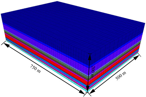
FIGURE 12. FLAC3D numerical simulation model.
4.2.2 Analysis of simulation results
During the excavation of the working face, the abutment pressure undergoes redistribution until stress stabilizes. As indicated by the research in the previous chapter regarding the movement laws of overburden, it is observed that the rear goaf area had been compacted and stabilized by the time the working face advanced to 180 m. Consequently, once the excavation of the working face reaches 200 m and stress redistribution stabilizes, the side abutment pressure distribution at monitoring points ceases to change. Figure 13 provides stress distribution contour maps at various depths within the side coal body when the working face has advanced 200 m from the measurement point, following stress stabilization.
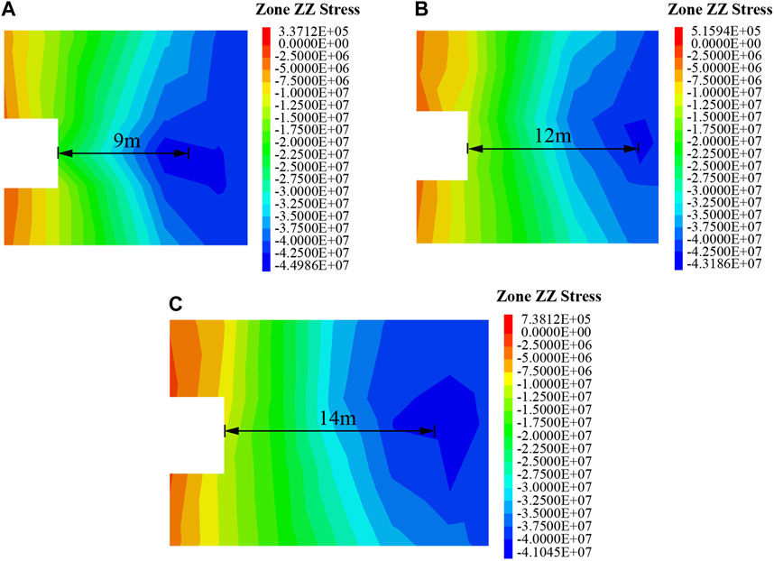
FIGURE 13. Stress contours at different depths within the side coal body. (A) measurement point a, (B) measurement point b, (C) measurement point c.
From Figure 13, it is evident that as the coal seam thickness at the monitoring point increases, the peak position of side abutment pressure shifts further away from the coal wall. The stress distribution of side abutment pressure at different depths from the coal wall displays distinct regional patterns. The area closer to the coal wall experiences stress reduction, where the abutment pressure falls below the original rock stress. This indicates that the surrounding rock within this region has undergone complete plastic deformation and lost its load-bearing capacity. Subsequently, the side abutment pressure sharply rises to reach its maximum, representing stress-concentration area. As the side abutment pressure extends deeper into the coal wall, it gradually diminishes until it ultimately matches the original rock stress.
The side abutment pressure distribution curves for different measurement points are depicted in Figure 14.
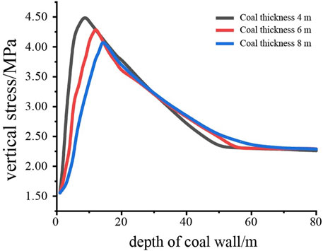
FIGURE 14. Side abutment pressure distribution curves at various monitoring points.
At coal seam thicknesses of 4 m, 6 m, and 8 m, the peak side abutment pressures within the stope are 44.98 MPa, 43.18 MPa, and 41.04 MPa, respectively. This illustrates that even within the same stope, side abutment pressure increases as the coal thickness increases.
The peak of side abutment pressure is situated at the edge of the coal wall’s limit equilibrium area. At coal seam thicknesses of 4 m, 6 m, and 8 m, the peak side abutment pressure occurs at distances of 9 m, 12 m, and 14 m from the coal wall, respectively. Within the same stope, with increasing coal thickness and mining height, the location of the peak side abutment pressure shifts deeper into the coal wall. Consequently, the extent of the limit equilibrium area also increases.
In the vicinity of the coal wall, the magnitude of the side abutment pressure is smaller than the original rock stress. This is because the coal body undergoes plastic deformation under the influence of concentrated stress, leading to a decrease in its load-bearing capacity. At this point, the magnitude of the side abutment pressure corresponds to the residual strength value of the coal body after it has undergone damage due to concentrated stress. The width of the tress-relaxation area is 3 m, 4 m, and 5 m for coal seam thicknesses of 4 m, 6 m, and 8 m, respectively.
5 Discussion
The research delves into the complexities of overburden movement behavior and side abutment pressure in stope characterized by varying coal seam thickness. It uncovers a significant relationship wherein an increase in coal seam thickness corresponds to a notable expansion in the immediate roof thickness of the working face. Concurrently, there is an observed decrease in the peak side abutment pressure, which relocates towards deeper sections within the coal wall. Previous studies predominantly conducted separate analyses of stope with distinct coal thicknesses to explore the impact of coal seam thickness on the working face. In contrast, this study concentrates on the variations in coal thickness within a singular stope. It has unveiled the dynamics of overburden movement and the distribution of side abutment pressure, highlighting the evolution of these patterns in accordance with changes in coal thickness and the directional progress within the mining site. The findings establish a foundational understanding for optimal coal pillar sizes in areas with varying coal seam thickness and offer actionable guidance for implementing monitoring techniques to mitigate ground pressure hazards in mining operations. In the future, further research will explore cases with more significant variations in coal seam thickness to supplement and expand upon this line of study.
6 Conclusion
1) Through theoretical analysis and numerical simulation, the movement law of the overburden was investigated. During the advancement process, as the coal thickness continuously increased, and the mining height expanded, the subsidence of the overlying strata consistently increased. This led to changes in the fracture patterns of the roof, and the thickness of the immediate roof also continued to increase. The roof is composed of a “Combined cantilever beam-Voussoir Beam” structure. According to calculations, the initial thickness of the immediate roof was 4 m at the beginning of mining, and it would increase to 18 m in the later stages of mining.
2) The subsidence curves of the overburden in coal seam thickness-varying stopes exhibit significant differences compared to those in stopes with uniform coal thickness. The subsidence curves in coal seam thickness-varying stope display asymmetry, with rock layers closer to the coal seam showing more pronounced asymmetry.
3) The analysis of side abutment pressure distribution laws in coal seam thickness-varying stope based on the limit equilibrium theory revealed that as coal thickness and mining height increase, the peak of side abutment pressure shifts deeper into the coal wall. Numerical simulation results demonstrated that at coal seam thicknesses of 4 m, 6 m, and 8 m, the peak side abutment pressure were 44.98 MPa, 43.18 MPa, and 41.04 MPa, respectively. The peak positions of side abutment pressure were located at distances of 9 m, 12 m, and 14 m from the coal wall, and the stress-relaxation area measured 3 m, 4 m, and 5 m, respectively.
By analyzing the changing laws of overburden movement and side abutment pressure distribution in coal seam thickness-varying panels, we gain a comprehensive understanding of the characteristics of roof movement and structural features under different coal seam thickness conditions. It remarkably contributes to both social and economic benefits by enabling safe and efficient extraction in working areas with variable coal thickness. Through the judicious determination of coal pillar sizes within sections, it effectively reduces coal resource losses, guides scientific ground pressure impact prevention, and promotes sustainable mine development. This approach significantly influences other coal mines facing coal thickness variations, offering guidance in selecting optimal coal pillar sizes, preventing ground pressure impacts, and employing boreholes for pressure relief.
Data availability statement
The original contributions presented in the study are included in the article/Supplementary material, further inquiries can be directed to the corresponding author.
Author contributions
YY: Writing–original draft, Writing–review and editing. LM: Writing–original draft, Writing–review and editing. LY: Writing–review and editing.
Funding
The author(s) declare financial support was received for the research, authorship, and/or publication of this article. This research was supported by the National Natural Science Foundation of China (Grant No. 52074166) and the Natural Science Foundation of Shandong Province of China (Grant No. ZR2022ME195).
Conflict of interest
The authors declare that the research was conducted in the absence of any commercial or financial relationships that could be construed as a potential conflict of interest.
Publisher’s note
All claims expressed in this article are solely those of the authors and do not necessarily represent those of their affiliated organizations, or those of the publisher, the editors and the reviewers. Any product that may be evaluated in this article, or claim that may be made by its manufacturer, is not guaranteed or endorsed by the publisher.
References
Gao, X. J., Zhang, H. Q., Zhang, Z., Li, S. J., and Hai, Y. F. (2022). Research on coal pillar size of gob-side entry driving and surrounding rock control technology in extra-thick coal seam. Coal Technol. 41 (01), 36–40. doi:10.13301/j.cnki.ct.2022.01.008
Li, J. S., Liu, C., and Han, J. G. (2009). Analysis of the geological causes of coal seam thickness variations. Coal Mine Mod. (02), 27–28. doi:10.13606/j.cnki.37-1205/td.2009.02.007
Liu, J., Chen, S. L., Wang, H. J., Li, Y. C., and Geng, X. (2015). The migration law of overlay rock and coal in deeply inclined coal seam with fully mechanized top coal caving. J. Environ. Biol. 36 (4), 821–827.
Liu, K. (2021). “Study on the law of rock-burst appearance in the area of coal seam thickness variation of Jian-xin mine,” ([Bei Jing]: Chine University of Mining and Technology). [master's thesis].
Liu, X. F., and Liang, X. S. (2018). The occurrence characteristics and the cause analysis of thickness change of 5 coal seam in xintai coal mine. Sichuan Build. Mater. 44 (03), 83–84. doi:10.3969/j.issn.1672-4011.2018.03.041
Nan, H., and Wang, S. (2022). Migration law of different top coal thicknesses in top coal caving. Front. Earth Sci. 10. doi:10.3389/feart.2022.999979
Qian, M. G., Shi, P. W., and Xu, J. L. (2010). Mine pressure and rock control. Xu Zhou: Xuzhou China University of Mining and Technology Press.
Ren, Z. P., Wang, C. Q., Jiang, B. Y., Shen, T. F., and Xiao, Z. M. (2014). Numerical simulation on influence of coal seam thickness variation on rock burst danger. Saf. Coal Mines 45 (12), 51–53+57. doi:10.13347/j.cnki.mkaq.2014.12.014
Shang, X. Q., Yang, H. Y., Ai, G., Zhang, Y. G., and Zhu, G. A. (2020). Mining-induced stress changes and rock burst effect in thickness variation of a coal seam. China Min. Mag. 29 (07), 148–151+157. doi:10.12075/j.issn.1004-4051.2020.07.002
Song, Z. Q. (1988). Practical mine pressure control. Xu Zhou: China University of Mining and Technology Press.
Song, Z. Q., Hao, J., Shi, Y. K., Tang, J. Q., and Liu, J. K. (2019). An overview of connotation and development of practical ground pressure contorl theory. J. Shandong Univ. Sci. Technol. Nat. Sci. 38 (01), 01–15. doi:10.16452/j.cnki.sdkjzk.2019.01.001
Song, Z. Q., and Jiang, J. Q. (1996). Research focus and direction of coal mine rock control. Chin. J. Rock Mech. Eng. 15 (02), 33–39.
Wang, S. W., Mao, D. B., Pan, J. F., Chen, J. G., Chen, F. B., and Lan, H. (2015). Measurement on the whole process of abutment pressure evolution and microseismic activities at the lateral strata of goaf. J. China Coal Soc. 40 (12), 2772. doi:10.13225/j.cnki.jccs.2015.0080
Wang, Y., Yang, B., Deng, C., Zhang, J. H., and Lu, M. (2017). Numerical simulation analysis of influende of coal thickness change on rock burst. Saf. coal Mines 48 (05), 198–201. doi:10.13347/j.cnki.mkaq.2017.05.055
Xie, G. X., and Wang, L. (2010). Thickness effects of fracture characteristics of coal seam and surrounding rocks in fully mechanized top-coal caving face. J. China Coal Soc. 35 (02), 177–181. doi:10.13225/j.cnki.jccs.2010.02.010
Xie, G. X., Yang, K., and Liu, Q. M. (2006). Study on distribution laws of stress in inclined coal pillar for fully-mechanized top-coal caving face. Chin. J. Rock Mech. Eng. (03), 545–549. doi:10.3321/j.issn:1000-6915.2006.03.017
Xie, J. W. (2020). Analysis on prevention and control of rockburst in thick coal seam. Mining.Energy Energy Conservation (06), 15–16. doi:10.16643/j.cnki.14-1360/td.2020.06.007
Xu, J. L., and Qian, M. G. (2000a). Method to distinguish key strata in overburden. J. China Univ. Min. Technol. 29 (05), 21–25. doi:10.3321/j.issn:1000-1964.2000.05.005
Xu, J. L., and Qian, M. G. (2000b). Study on the influence of key strata movement on subsidence. J. China Coal Soc. 25 (02), 122–126. doi:10.13225/j.cnki.jccs.2000.02.003
Xu, Y. X., Li, H. M., Wang, K. L., and Yuan, R. P. (2014). Study on lateral support pressure distribution of fully - mechanized coal mining face in ultra thick seam. Coal Sci. Technol. 42 (11), 26–28. doi:10.13199/j.cnki.cst.2014.11.008
Yang, D. F. (2023). Analysis on fracture mechanics theory of roof cutting instability mechanism with large mining height face in shallow coal seam. Front. Earth Sci. 10. doi:10.3389/feart.2022.900144
Yu, L. (2013). “Study on the law of roof movement and support working resistance determination of fully-mechanized top-coal caving with great mining height,” ([Bei jing]: China Coal Science Research Institute). [dissertation].
Yu, L., Yan, S. D., and Liu, Q. M. (2012). Determining support working resistance of top coal caving in extra thick coal seam. J. China Coal Soc. 37 (57), 737–742. doi:10.13225/j.cnki.jccs.2012.05.018
Yu, X., Zhao, K., and Wang, Q. (2020). Relationship between movement laws of the overlaying strata and time space of the mined-out. Geofluids 2020, 2020. doi:10.1155/2020/2854187
Zhang, Y. J., Kong, J. Y., Long, S. F., Zhu, W. X., and Wu, T. H. (2022). Study on the ground fissure development law of coal mining based on UAV photogrammetry and the particle flow theory. Front. Environ. Sci. 10. doi:10.3389/fenvs.2022.915645
Zhao, T. B., Guo, W. Y., Tan, Y. L., Zhang, Z., and Cheng, K. K. (2016). Mechanics mechanism of rock burst caused by mining in the variable region of coal thickness. J. China Coal Soc. 41 (07), 1659–1666. doi:10.13225/j.cnki.jccs.2015.1475
Keywords: coal thickness variation, overburden movement, roof structure, side abutment pressure, numerical simulation
Citation: Yang Y, Meng L and Yuan L (2023) Analysis of overburden movement and side abutment pressure distribution in deep stope with varying coal seam thickness. Front. Earth Sci. 11:1323679. doi: 10.3389/feart.2023.1323679
Received: 18 October 2023; Accepted: 20 November 2023;
Published: 28 December 2023.
Edited by:
Peng Huang, China University of Mining and Technology, ChinaReviewed by:
Qiangling Yao, China University of Mining and Technology, ChinaL. Chen, China University of Mining and Technology, China
Guangtan Cheng, Shandong Agricultural University, China
Copyright © 2023 Yang, Meng and Yuan. This is an open-access article distributed under the terms of the Creative Commons Attribution License (CC BY). The use, distribution or reproduction in other forums is permitted, provided the original author(s) and the copyright owner(s) are credited and that the original publication in this journal is cited, in accordance with accepted academic practice. No use, distribution or reproduction is permitted which does not comply with these terms.
*Correspondence: Lingren Meng, bWVuZ2xpbmdyZW5Ac2R1c3QuZWR1LmNu