 Si-Si Shi1
 Zhi-Hui Wan
 Tao Hu
94% of researchers rate our articles as excellent or good
Learn more about the work of our research integrity team to safeguard the quality of each article we publish.
Find out more
ORIGINAL RESEARCH article
Front. Earth Sci., 29 December 2023
Sec. Geohazards and Georisks
Volume 11 - 2023 | https://doi.org/10.3389/feart.2023.1323213
Reasonable control of grouting parameters was the key to improving the pile-soil interaction. However, quantitative analysis on the effect of grouting parameters on the pile-soil interaction was still lacking. This article developed an intelligent post-grouting system for precise control and quantitative analysis of grouting parameters. The conventional preparation method for shear tests were improved in this article. By changing the normal stress of the pile-soil interface during grouting, the test sample could simulate the grout distribution of the pile-soil interface at different depths. Through the improved experimental methods, a more accurate analysis of the mechanism for the pile-soil interaction was achieved. And the effectiveness of the intelligent post-grouting system was further verified by the case application. The results indicated that increasing the grout volume could improve the interface shear strength when the normal stress and grouting pressure were constant. This improvement effect caused by increasing grout volume decreased when the normal stress was high. Increasing the grouting pressure increased the interface shear strength when the normal stress and the grout volume remained constant. This improvement effect caused by increasing grouting pressure decreased when the grout volume was small. By appropriately controlling the two grouting parameters, the cohesion and the shear strength of the pile-soil interface were increased by 5.8–18.8 times and 1.16–2.91 times, respectively. The results indicated that the intelligent post-grouting system could accurately control the grouting parameters and effectively improve the pile-soil interaction of bored piles. The intelligent post-grouting system effectively reduced geotechnical engineering risks and improved the bearing capacity of pile.
Deep foundations are essential for all major infrastructure projects (Li et al., 2016). At present, the building height is approaching 1,000 m, the bridge span is exceeding 2,000 m, and offshore wind power is reaching 50 m deep (Feng et al., 2016). This causes the size of the foundation steadily grows to greater diameters and super-long lengths (Yan et al., 2022). The use of large diameter and super-long piles required a large amount of concrete and freshwater resources, as well as an increase in drilling machinery operation time. This resulted in massive resource waste and environmental damage, making it difficult to satisfy the goals of green and low-carbon development (Thiyyakkandi et al., 2022). Post-grouting was regarded as an efficient method to solve the above difficulties and improved the bearing capacity of piles. According to the report in reference (Hu et al., 2023a), the post-grouting technology could effectively improve the ultimate lateral resistance by 37.31%–60.27% and the ultimate end resistance by 39.77%–67.39%. After post-grouting, the ultimate bearing capacity of piles increased by 38.03%–61.87%.
Hu et al., 2023b conducted full-scale field tests on large diameter grouted bored piles with different lengths. The test results indicated that the post-grouting could greatly shorten the length and diameter of the pile, reducing the consumption of concrete and fresh water and lowering carbon emissions. Wan et al., 2022 verified the effectiveness of post-grouting to improve the horizontal bearing capacity of piles through model tests. The test results indicated post-grouting was a resource-intensive foundation treatment method that was also a critical technological means of achieving green and low-carbon construction. Hu et al., 2022a proposed that it was unable to directly evaluate its construction quality and grouting consequences since the post-grouting technique took place underground. As a result, it was important to analyze and evaluate the changes in grouting parameters during the post-grouting process (Wan et al., 2019). Mullins et al., 2006 proposed that the critical control grouting parameters such as grout volume, grouting pressure, grout flow rate, and water-cement ratio determined the quality of post-grouting construction. Therefore, timely and precise control of grouting parameters was essential for effectively increasing the bearing capacity of pile foundations and ensuring post-grouting quality (Xing and Wu, 2020).
Mullins, 2016 proposed a design method for post-grouted piles based on grouting pressure to predict the enhanced coefficient of pile end resistance based on field test results. Hu et al., 2022b established a grouting pressure calculation formula suitable for the soil of the Yellow River Basin by statistical method. The results from the field static load results demonstrated that the application of post-grouting with grouting pressure determined by the aforementioned formula significantly improved the bearing capability of the pile foundation. Currently, the adjustment of grouting parameters primarily relies on manual control, resulting in a significant impact on the quality of post-grouting due to human factors (Shrivastava and Zen, 2018). Consequently, it was of greatest importance to correctly regulate the grouting parameters during the post-grouting construction procedure. Sinnreich and Simpson (Sinnreich and Simpson, 2015) performed static load experiments on one grouted test pile and one ungrouted test pile at the same site using the O-cell method. The experimental results revealed that the grouted pile exhibited lower pile top displacement and larger ultimate bearing capacity compared to the ungrouted pile when the pile top load was above 5000 kN. Through a large number of measured data points, Liu and Wan (Liu and Wan, 2018) confirmed the limitations of post-grouted piles; that is, post-grouting might have a limited influence on improving the settlement performance of bored piles under the operating limit state. Even under identical conditions, the pile top top displacement of the grouted pile might be greater than that of the ungrouted pile. Zhu proposed that (Zhu, 2020) the previous results might be attributed to non-standard control of grouting parameters and the grouting procedure, resulting in a high degree of discreteness in the bearing capacity of test piles after post-grouting.
However, the above research were only qualitatively studies, and failed to further quantitatively analyze the effects of grouting parameters, normal stress on the pile-soil interaction. The pile-soil interaction referred to the mechanical interaction between the pile and the soil. Due to the contact and friction between the pile and the soil, the interaction force would be generated. The existing shear test could not simulate the grout distribution on the pile-soil interface under different normal stresses. This mighty lead to the inaccuracy of the pile-soil interaction mechanism obtained by the existing shear test. In view of the above problems, the author developed an intelligent post-grouting system to simulate the post-grouting process more realistically. The author improved the conventional preparation method for shear tests. By changing the normal stress of the pile-soil interface during grouting, the test sample could simulate the grout distribution of the pile-soil interface at different depths. Through the improved experimental methods, a more accurate analysis of the mechanism for the pile-soil interaction was achieved. The researchers conducted interface shear tests on the grouted samples in order to investigate how different grouting parameters influence the shear mechanical properties of the pile-soil interface. This article provided technical references for the a effective control of grouting parameters to reduce geotechnical engineering risks. Limited by the length of the article, the author only analyzed the influence of grout volume, grouting pressure and normal stress in detail. In the future, the author would further study the influence of flow rate, water-cement ratio on the pile-soil interaction.
This study aims to investigate the impact of grouting parameters on the mechanical characteristics of the pile-soil interface. The shear test primarily focused on three key control parameters: grouting pressure, grout volume, and interface normal stress. The grouting pressure and grout volume were crucial parameters during the grouting process. Different interface normal stresses were employed to replicate the soil pressure at varying depths, in order to better assess the impact of grouting parameters on the effectiveness of grouting in soils at different depths.
The interface shear test consisted of three parts: preparation of test samples, grouting tests, and shear tests, which were designed to simulate the failure of the pile-soil interface of post-grouted piles.
(1) Preparation of test samples: the concrete slab was used to simulate the body of grouted piles, and the pressure-resistant hose was used to simulate the grouting pipe, a mold with the same plane size as the shear box under the direct shear instrument was designed and manufactured.
(2) Grouting tests: the grouting pressure was controlled by a combination of an air compressor and a pressure-regulating valve. To accomplish accurate control of the grout volume, a self-designed intelligent grouting system comprised of electromagnetic valves, relays, control boards, communication electronic scales, and voltage stabilizing power supply was implemented. A jack with a digital display meter and a reaction frame were used to control the normal stress during the grouting process.
(3) Shear tests: The mechanical factors of the pile-soil interface at different depths were reflected by the combined operation of the vertical and horizontal loading systems of the shear apparatus. Preliminary testing was conducted to determine the suitable grout volume, grouting pressure, and interface normal stress to enhance the effectiveness of grouting model experiments. The grout volume was designed to be 240 mL, 480 mL, and 720 mL. The grouting pressures were designed to be 500 kPa, 650 kPa, and 750 kPa. The normal stresses were designed to be 50 kPa, 100 kPa, and 150 kPa. The parameters and number of test samples were provided in Table 1.
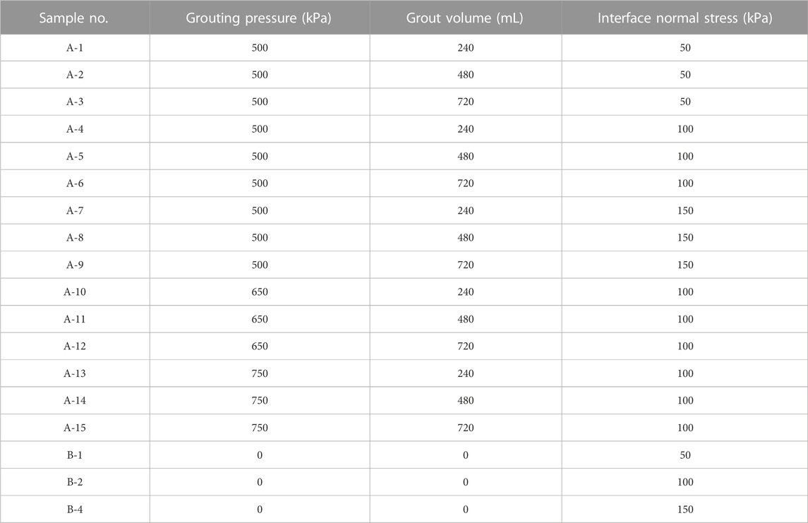
TABLE 1. Number of test samples with different parameters.
The purpose of the interface shear test was to explore the interaction of the pile-soil interface of post-grouted piles. To simulate the pile surface, a concrete slab with the same shear mechanical properties as the pile surface was used. The production process of concrete slabs was strictly regulated to maintain consistent surface roughness across all test groups. A set of iron molds with the same internal plane size as the shear box was created. The dimensions of the mould plane were 477 mm in length, 295 mm in width, and 56 mm in height. The weighed aggregate, sand, cement, and water were combined in a concrete mixer for 10 min to guarantee that the physical qualities of each batch of concrete were the same. Before the process of pouring concrete, the demolding agent was applied by brushing it onto the interior surface of the mold. During the concrete pouring process, a handheld vibrating device was utilized to induce vibration and facilitate the expulsion of internal air bubbles.
The pressure-resistant hose and the connector form a grouting pipeline, which was embedded in the plate during pouring, as shown in Figure 1. After 7 days of concrete slab curing, the surplus hose of the grouting pipe was removed, and the surface of the concrete slab was smoothed by the angle grinder. The thickness of the concrete slab was controlled to be 55 mm, and the flatness of the surface was monitored in real-time with a level meter, as shown in Figure 1C. The particle size range of the test sand was 0.075 mm–1.5 mm, and the particle size distribution curve was shown in Figure 2. Xu and Zhang (Zhou et al., 2021) pointed out that there was no particle size effect when the size of the model structure was greater than 23 times the particle size of the model soil. Therefore, the results of this experiment were not affected by the particle size effect.
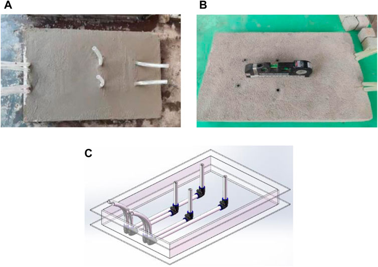
FIGURE 1. Concrete slab production and grouting pipe layout: (A) making concrete slabs; (B) testing the flatness of concrete slabs; (C) layout of grouting pipes in concrete slabs.
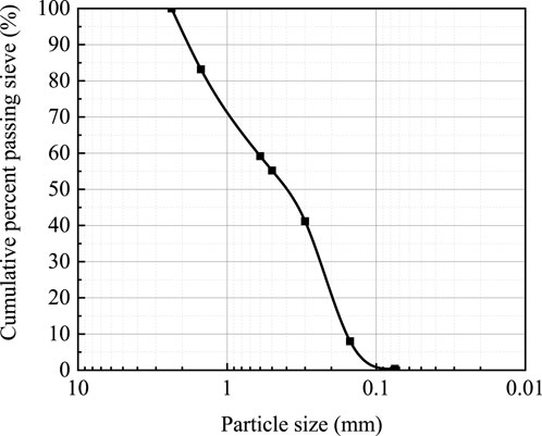
FIGURE 2. The particle size distribution curve.
An intelligent grouting control system was designed to achieve accurate regulation of grout volume and grouting pressure during grouting tests. The system was comprised of three distinct sub-systems, including the control system, grout storage system, and pressure supply system. The overall arrangement of the grouting system is shown in Figure 3.
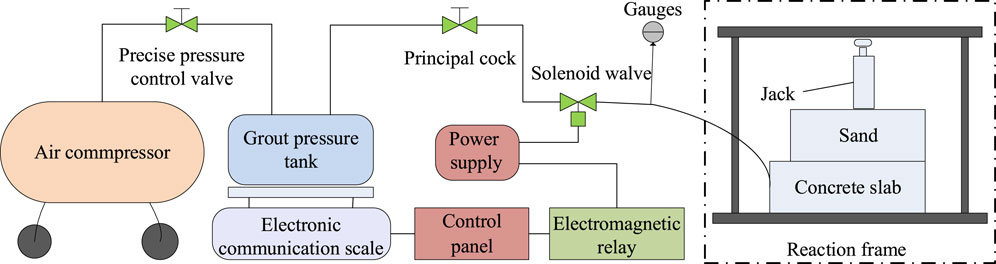
FIGURE 3. The overall arrangement of the grouting system.
(1) Intelligent grouting control system.
The control system was mainly composed of the solenoid valve, an electromagnetic relay, an MCU main control board, a regulator power supply, and a pressure gauge, the main function was to control the grout volume and monitor the grout pressure. The solenoid valve was a usually open DC12V type with a 16 mm flow aperture, which had a normally open valve in the off state and an instantaneous valve closure in the on state. The SRD-03VDC type relay possessed the capability to control the on-off of the entire circuit. The control board adopted an STM32 series single-chip microcomputer with an ARM Cortex-M core. It was the core component of the whole grouting control system. The program of the main control board was written in the C language. The solenoid valve was operated using the GOPHERT NPS-3001 regulated power supply, which was capable of providing a stable direct current (DC) output within the range of 0–30 V and 0–10 A. To monitor the grouting pressure, the gauge with a range of 0–1.6 MPa was connected to the grouting pipe. The intelligent grouting control system components were depicted in Figure 4.
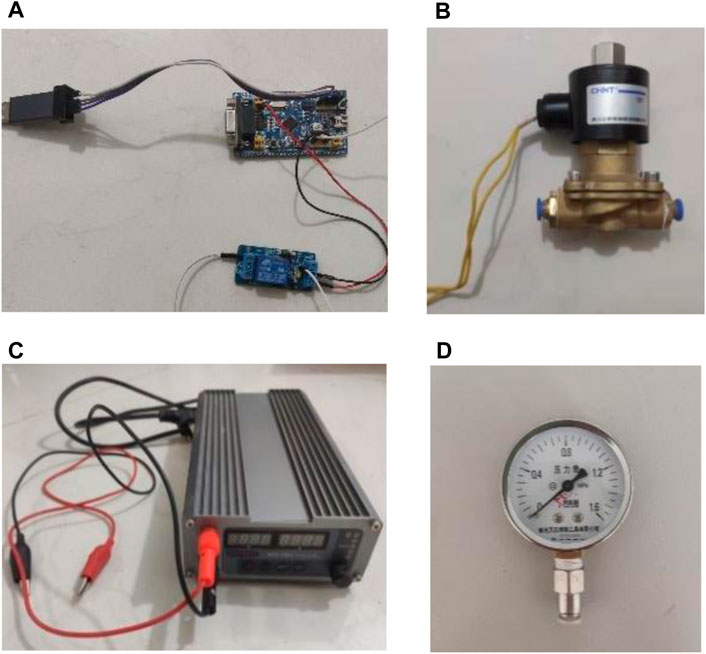
FIGURE 4. The components of the control system: (A) electromagnetic relay and control board; (B) solenoid valve; (C) regulated power supply; (D) gauge.
(2) Grout storage system.
The grout storage system consisted of a grout tank and an electronic scale with a communication function, which functioned to store the grout and output its weight change. The cylindrical grout tank was made of carbon steel and had a vertical dimension of 300 mm and an internal diameter of 151 mm. It could hold 4 L of grout and had a maximum pressure tolerance of 1 MPa. The working concept was to convert the air input from the air compressor into power to output cement grout. Electronic scale with RS232 serial interface that could output weight signals in real time at a rate of 9600 bytes per second. Its function was to transmit the weight change of the grout tank to the control board in real time during the grouting process.
(3) Pressure supply system.
The pressure supply system was responsible for supplying pressure to the entire grouting equipment, which consisted of an air compressor and a precise pressure-control valve. The air compressor was an oil-free air compressor with a matching power of 780 W and a speed of 1,380 r/min, which could continuously provide a pressure of 0.9 MPa. The rated air pressure of the air pressure regulating valve was 1.0 MPa. The knob adjusted the air pressure output of the air compressor to modify the grouting pressure. The components of the pressure supply system were shown in Figure 5.
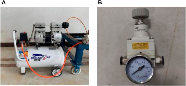
FIGURE 5. Details of pressure supply system components: (A) air compressor; (B) precision pressure regulating valve.
Firstly, the air compressor outputted the specified air pressure through the precision pressure regulating valve. After the air pressure enters the pressure grout tank, high air pressure drives the grout out through the hose. Secondly, after starting the grouting device, keep the solenoid valve open. The electronic scale outputed real-time weight data of the grout storage pressure bucket to the control board. Finally, when the specified grout volume was reached, the control board sent a control signal to automatically close the solenoid valve. The working process of the grouting system was shown in Figure 6.
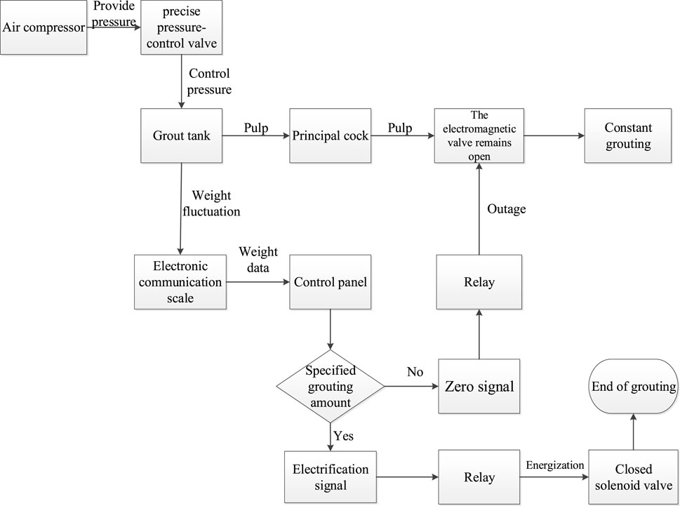
FIGURE 6. Working process of the grouting system.
The concrete slab indicated above was chosen and placed in a removable mold box. The second detachable mold box was put on the concrete plate, and its internal dimensions matched the size of the shear box for the shear apparatus. The concrete slab was placed in the first mold box. The second mold box was put on the concrete plate, and its internal dimensions matched the size of the shear box for the shear apparatus. The second mold box filled with sand was put on the concrete plate, and its internal dimensions matched the size shear box on the shear apparatus. After laying 1 cm thick sand in the model box, the sand was hammered 100 times with a rubber hammer, and then the surface of the sand layer was scraped. Repeated the above steps until the sand layer was filled to 8 cm thick. Then, the sand layer was compacted by the static pressure of the steel plate, and the jack applied the normal load to the sand according to the test scheme. The sand layer was subjected to load pressure for 1 h before the next test step, making the consolidation settlement be finished rapidly.
According to literatures (Yang et al., 2019) and pre-test results, the water-cement ratio of the grout was 0.7 to ensure the grout injectability.After connecting the grout storage system, control system, and pressure supply system, the water injection test was carried out after adjusting the reverse pressure of the jack. The water injection test had three goals: 1) the first was to determine the injectability of the entire soil layer; 2) the second was to modify the pressure-regulating valve to output the proper grouting pressure; 3) and the third was to test the operational stability grouting system. Following the completion of the water injection test, an adequate volume of cement grout was poured into the grout tank. After connecting the grouting pipe between the slurry tank and the concrete slab, grouting could begin. The grouting process was shown in Figure 7. After the grouting was completed, the normal pressure was kept constant and maintained for 3 days. Figure 7C showed the long side of the concrete slab after cleaning, and the marks covered by the cement grout along the surface of the concrete slab could be seen clearly, suggesting that the grouting test had a positive effect.
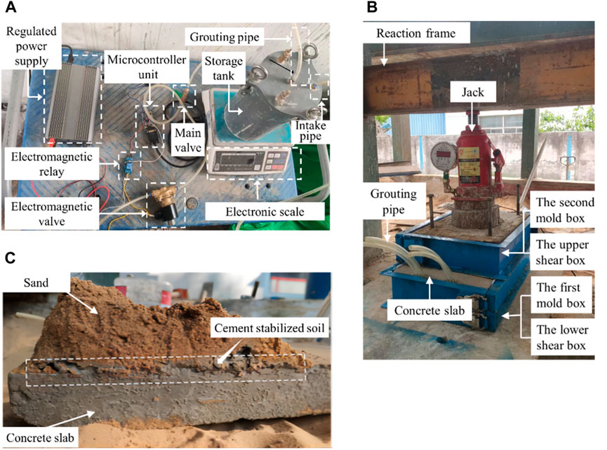
FIGURE 7. Grouting process of test samples: (A) the composition device of the indoor intelligent grouting system; (B) grouting of interface shear specimens; (C) pile-soil interface after grouting (sectional view).
To explore the influence of grouting parameters on the shear mechanical properties of the pile-soil interface, a self-developed direct shear apparatus was used. The instrument mainly includes a frame, shear box, horizontal loading system, vertical loading system and measurement control system, as shown in Figure 8. The shear box, horizontal loading system and vertical loading system were fixed on the instrument by welding and bolts. The size of the upper and lower shear boxes of the instrument was 400 mm × 300 mm × 100 mm (length×width×height) and 480 mm × 300 mm × 100 mm (length×width×height), respectively. The lower shear box was slightly longer than the upper shear box, which could effectively avoid the shear area remaining unchanged during the shear process.
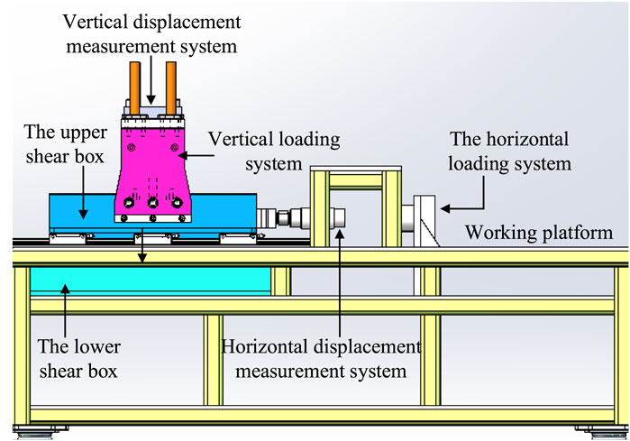
FIGURE 8. Schematic diagram of shear apparatus.
The horizontal loading system of the direct shear apparatus was mainly composed of servo-electric cylinder, pressure sensor, displacement sensor and limit device. The loading of shear force was realized by the screw drive of the linear servo electric cylinder. The maximum thrust of the electric cylinder was 25 kN, which had two modes of stress control and displacement control. The vertical loading system was composed of an air compressor, gas-liquid booster cylinder, precision pressure regulating valve, and pressure sensor. The maximum normal pressure could reach 50 kN. The pressure regulating device was set to stabilize the vertical pressure. At the same time, the air compressor provides pressure to the gas-liquid booster cylinder. By altering the precision pressure regulating valve, the vertical loading pressure could be arbitrarily changed. The measurement and control system was composed of computer, integrated controller, data acquisition software, pressure and displacement sensors. The data of pressure and displacement can be collected and analyzed in real time.
The interface shear test was carried out on the test samples listed in Table 1. The plank was pre-matted into the shear box, and then the test samples were hoisted into the shear box of the direct shear apparatus. The thickness of the wood slab was adjusted according to the actual situation, so that the surface of the concrete slab was located in the shear interface of the direct shear apparatus. The smoothness of the soil sample surface was controlled in real time by the leveler indicator. The schematic diagram and physical diagram of the control process were shown in Figure 9. After installing the vertical loading system, the normal pressure was applied on the test samples. The interface shear test began when the vertical pressure applied to the test sample reached the design value and remained stable. The shear rate was adjusted to 0.03 mm/s during the shear test, and the shear displacement and shear stress were measured every 0.1 s. The shear test was stopped when the shear displacement reached 40 mm.
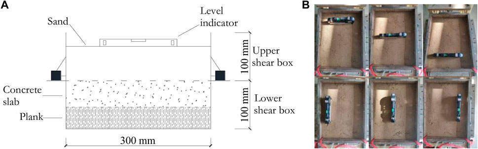
FIGURE 9. Smooth the surface of the soil sample: (A) the schematic diagram; (B) the physical diagram.
Figure 10 illustrated the shear stress-shear displacement curves (τ-s curves) of the pile-soil interface with different grout volume, under a grouting pressure of 500 kPa. Figure 10 showed that post-grouting greatly enhanced the shear mechanical characteristics of the pile-soil interface under different normal stresses. The τ-s curves of the grouted sample and the ungrouted sample were both nonlinear at the initial stage of the shear process, and no softening phenomenon was observed throughout the shear process.
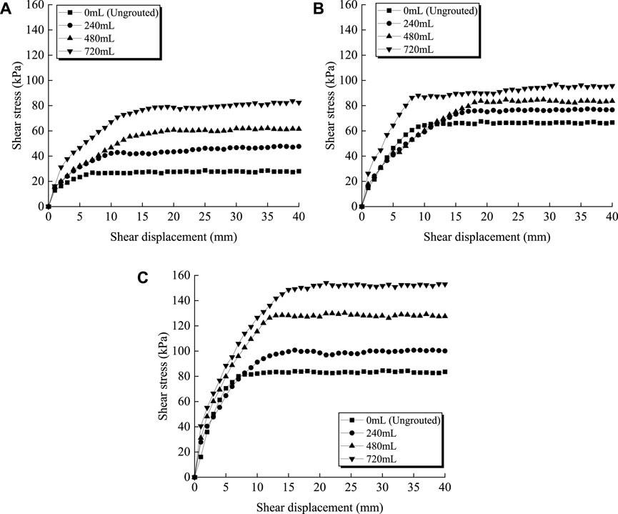
FIGURE 10. The τ-s curves of the pile-soil interface with different grout volume (grouting pressure was 500 kPa): (A) normal stress was 50 kPa; (B) normal stress was 100 kPa; (C) normal stress was 150 kPa.
The slope of the τ-s curves of the grouted sample in the initial stage of the shear process was greater than the ungrouted sample, and the initial shear modulus of the grouted sample was improved to varying degrees. As illustrated in Figure 10, the initial shear modulus of τ-s curves of the grouted pile-soil interface increased by 18.8%–25.6% when the interface normal stress was 50 kPa. The initial shear modulus of τ-s curves of grouted samples increased by 6.1%–77.0% when the interface normal stress was 100 kPa. The initial shear modulus of τ-s curves of grouted samples increased by 72.7%–152.0% when the interface normal stress was 150 kPa. The above results indicated that the initial shear modulus rose as the normal stress increased. On the other hand, Figure 10 also showed that the initial shear modulus rose with increasing grout volume under the same normal stress. And this trend was more noticeable at higher interface normal stress (i.e., at pile depth). It should be noted that when the interface normal stress was 100 kPa, the initial shear modulus of the sample with a grout volume of 240 mL did not increase significantly.
This phenomenon occurred due to the cement consolidation body in the sample reaching 8 cm, which led to a reduction in the thickness of the overlying sand layer. As a result, when the direct shear apparatus applied normal pressure, the cement consolidated body was crushed due to the lack of buffer of the overlying sand layer. The test results of the sample A-5 (normal stress was 100 kPa, grouting volume was 480 mL) and the sample A-7 (normal stress 150 kPa, grouting volume 240 mL) were affected by the above phenomena to varying degrees. The value of the first inflection point on the τ-s curve where the shear stress no longer increased significantly were defined as the ultimate shear stress. Figure 10 showed that the ultimate shear stress of the grouted samples was greater than that of the ungrouted samples, and it grew with increasing grout volume under the same normal load. The effect of increasing the grout volume to increase the ultimate shear stress gradually weakened as the normal stress increased. This indicated that there was an optimal grout volume.
For example, when the normal stress was 50 kPa, the ultimate shear stress of the ungrouted sample was only 27.9 kPa, as shown in Figure 10A. Figure 10A showed that the ultimate shear stress for grouted samples with 240 mL, 480 mL, and 720 mL of grout volume was 46.7 kPa, 60.5 kPa, and 81.3 kPa, respectively. The ultimate shear stress of grouted samples increased by 67.4%–191.4%. When the normal stress was 150 kPa, the ultimate shear stress of the ungrouted sample was 83.4 kPa, as shown in Figure 10C. Figure 10C showed that the ultimate shear stress for grouted samples with 240 mL, 480 mL, and 720 mL of grout volume was 100.1 kPa, 127.8 kPa, and 151.2 kPa, respectively. The ultimate shear stress of grouted samples increased by 20.0%–61.9%, and the enhancement effect of grouting was reduced. This revealed that as the depth of the grouting position increased, the effect of enhancing side resistance by increasing the grout volume gradually decreased.
The previous results were attributable to the low density and large porosity of sand under low normal stress, which made it simpler for cement grout to permeate and disseminate in the sand, hence improving sand strength. For the grouted sample under high normal stress in Figure 10C, the density of sand was higher. Cement grout diffused in the form of compacted grouting in the sand (El-Kelesh et al., 2012; Zhang et al., 2020). The diffusion range of grout was reduced for the same grout volume, resulting in a poor improvement effect of grouting on the ultimate shear stress of sand.
Figure 11 illustrated the τ-s curves of the pile-soil interface with different grouting pressure, under a normal stress of 100 kPa. When the grout volume was 240 mL, the ultimate shearing stress of grouted samples improved by 14.7%–28.9%. When the grout volume was 480 mL, the ultimate shear stress of the grouted sample improved by 25.9%–40.5%. When the grout volume was 720 mL, the ultimate shearing stress of grouted samples improved by 41.7%–58.3%. The above results indicated that the ultimate shearing stress rose as the grout volume grew. Figure 11 also showed that under the same grout volume, the mechanical properties of the interface had different degrees of improvement according to the degree of increase of grouting pressure.

FIGURE 11. The τ-s curves of the pile-soil interface with different grouting pressure (normal stress was 100 kPa): (A) grout volume was 240 mL; (B) grout volume was 480 mL; (C) grout volume was 720 mL.
As demonstrated in Figure 11, when the normal stress was 100 kPa, the improvement effect of increasing the grouting pressure on the shear characteristics of the interface grew with increasing grout volume. It was worth noting that the τ-s curve of sample A-13 (grout volume was 240 mL, grouting pressure was 750 kPa) showed a sharp drop in shear stress. This might be due to partial cement soil and pile surface occlusion failure, causing the τ-s curve to enter the shear slip state and cause shear stress drop.
Figure 12 displayed the τ-s curves of the pile-soil interface with different normal stress, under a grouting pressure of 500 kPa. The initial shear modulus and ultimate shearing stress of the grouted sample and the ungrouted sample both improved as the normal stress increased.
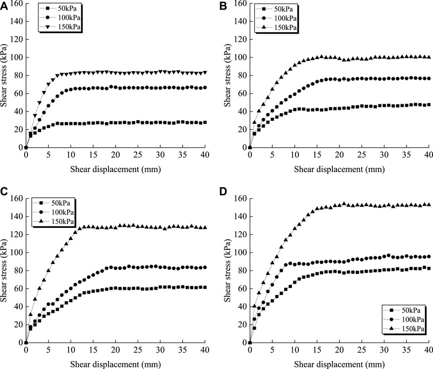
FIGURE 12. The τ-s curves of the pile-soil interface with different normal stress (grouting pressure was 500 kPa): (A) grout volume was 0 mL; (B) grout volume was 240 mL; (C) grout volume was 480 mL; (D) grout volume was 720 mL.
The ultimate shear stress of the τ-s curve generally increased after post-grouting. Therefore, the reinforcing coefficient was defined as the ratio of the ultimate shear stress of the grouted specimen to the ultimate shear stress of the ungrouted specimen. The ultimate shear stress under different normal stresses and grout volume was calculated, and the shear strength enhancement coefficient for the pile-soil interface of the post-grouted pile was obtained as 1.16–2.91. The value of the enhancement coefficient grew as the amount of grout increased, whereas it decreased first and then increased as the normal stress increased.
Figure 13 depicted the ultimate shear stress line diagram of the pile-soil interface under various normal stresses and grout volume. In Figure 13, the ultimate shear stress of the pile-soil interface of the post-grouted pile increased linearly as normal stress increased. The enhancement effect of post-grouting on the shear performance of the pile-soil interface also increased with the increase of grout volume.

FIGURE 13. The relationship between ultimate shear stress and normal stress.
The association between normal stress σ and ultimate shear stress τu were linearly fitted under different grout quantities, as illustrated in Figure 13. The shear mechanical properties of the interface followed the Mohr-Coulomb criterion before and after grouting. The equivalent cohesion c and equivalent internal friction angle φ of the interface were determined indirectly from the fitting curve, as shown in Table 2.
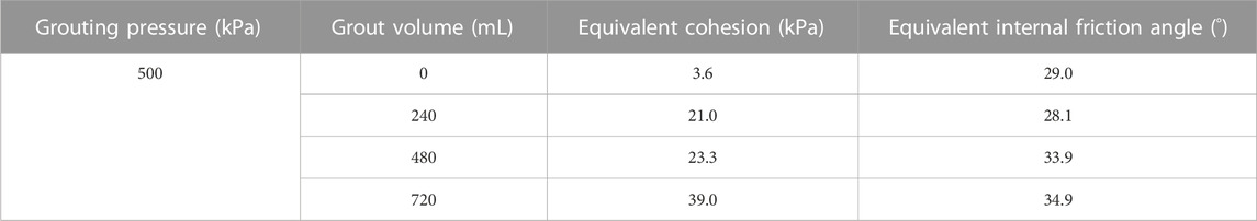
TABLE 2. Equivalent cohesion and equivalent internal friction angle of pile-soil interfaceafter post-grouting.
Table 2 shows that after grouting, the equivalent cohesion under each working condition increased by 5.8–18.8 times. The increase in equivalent cohesion increased with the increase in grout volume. However, the equivalent internal friction angle increased slightly with the increase in grout volume.
This was due to the fact that, prior to grouting, the pile-soil interface was primarily sheared by shear force, and shear failure typically occurred at the pile-soil contact interface (Li et al., 2022; YuZhou and GongZhang, 2023). However, the object sheared by shear force was changed into the contact interface of pile-cement-soil coexistence after grouting. Yu et al., 2021. (Yu et al., 2023) proposed that the shear failure of the interface occurred on the contact surface of the cement stone-cement soil after grouting. The cement grout gradually filled the pores of the sand soil with the continuous injection of pressure cement grout, such that the small sand particles became cement soil particles with a high biting force (Wu et al., 2020).
Furthermore, as the cement hydration reaction progressed, the original flocculent hydrated calcium silicate eventually transformed into fibrous and connected with each other. This brought the cement stone body and pile surface closer together, improving the overall working efficiency of the pile-cement-soil interface (Wang et al., 2023). From a macro perspective, injecting cement grout greatly increased the roughness of the pile-soil contact interface (Moayed et al., 2019; Li et al., 2021). Lee et al., 2020 proposed that increasing roughness significantly raised contact interface cohesion but had minimal influence on contact interface friction angle, which was also compatible with the results of this experiment.
An intelligent grouting control system was developed based on electronic sensor and microcomputer technology. The system could effectively control and measure the key parameters such as grouting amount and grouting pressure. The system comprised the intelligent grouting equipment, the mainframe, and the data collection system. The overall arrangement of the intelligent grouting control system was shown in Figure 14.
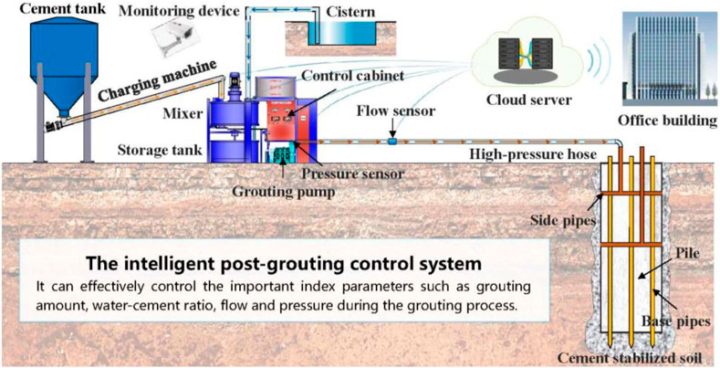
FIGURE 14. Schematic diagram of intelligent post-grouting control system for bored piles.
The intelligent grout equipment comprised grout pumps, the mixer, the grout tank, grout pipelines, and control cabinets. The mainframe comprised the microcontroller system, an input component, and an output component. The sensors comprised weight flow meters, pressure sensors, and target flow meters. The intelligent grouting system could achieve a fully automated operation. Intelligent grouting equipment could properly control grouting pressure and grout volume to automate post-grouting. The integration of a frequency converter with a grout pump enabled the control of the desired grouting pressure and the grout volume.
During the grouting process, the control cabinet was in charge of collecting real-time data from the weighing meter, pressure sensors, and flow meters. The mainframe transmitted a signal to the relay once the predetermined grouting parameters were met. The relay then restored power to the solenoid valve, which rapidly closed to end the grouting procedure. It should be noted that the effective output of key grouting parameters ensured construction safety and improved grouting quality. Furthermore, the system could record the entire grouting process and synchronously upload various grouting parameters utilizing wireless devices, making the grouting process more visible.
A large-diameter test pile with a diameter of 2.0 m and a length of 52 m was chosen as an example to evaluate the effectiveness of the self-developed intelligent grouting parameter control system. The bearing layer of the test pile was fine sand layer, and the bearing capacity was enhanced by combined end-and-side grouting. The specific parameters of the test pile were provided in the reference (Wan, 2019). The combined end-and-side grouting was completed in the following order: pile side grouting first, followed by pile end grouting. The interval between pile side grouting and pile end grouting should not be less than 2 h. For pile side grouting using multiple grouting sections, the process was performed from top to bottom of the grouting section.
The cement grout was produced with P.O42.5 Portland cement and the proportion of water to cement of 0.5. The setting values of grouting parameters were shown in Table 3. During the grouting operation, the grouting parameters were adjusted and recorded in real time employing the self-developed automatic controller and data gathering system. Figure 15 depicted variable curves for key grouting parameters such as grouting pressure, grout flow, and grouting volume of each grouting pipe of the test pile over time. The test pile TP4 # was selected for detailed analysis.
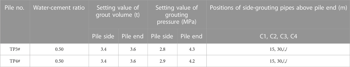
TABLE 3. The setting value of grouting parameters.
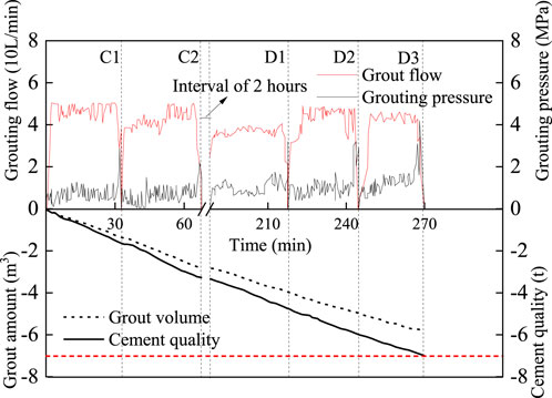
FIGURE 15. Variable curves of grouting parameters with time for test pile.
Figure 15 demonstrated how the grouting pressure and grout volume changed over time during the grouting process. Finally, the grout volume was controlled at 7.0 t, the termination grouting pressure was controlled at 2.2 4.2 MPa, and the slurry flow rate was controlled at 35 50 L/min. The grouting parameters listed above all satisfactorily meet the design requirements. The above test results demonstrated that the intelligent grouting parameter control system could better regulate the grouting parameters dynamically throughout the grouting process, allowing the engineer to precisely and rapidly grasp the site grouting situation and evaluate the grouting effect. The intelligent control system reasonably adjusted the grouting parameters such as grouting pressure, grout flow and water cement ratio, making the post-grouting operation more reasonable and standardized.
The influence of grouting parameters on the shear characteristics of the pile-soil interface was investigated in this paper by performing interface shear tests of grouted piles. Furthermore, field tests were conducted to further demonstrate the significant impact of grout volume and grouting pressure on the bearing performance of bored piles. Finally, the self-developed intelligent grouting parameter control system was applied to engineering practice and the effectiveness of the system was verified. The following conclusions were drawn from the test findings and analysis.
(1) When the interface normal stress and grouting pressure remained constant, the ultimate shear stress and initial shear stiffness of the interface rose as the grout volume increased. After grouting, the increase in the initial shear stiffness of the interface was more noticeable under higher normal stress. However, the effectiveness of increasing the grout volume to increase the ultimate shear stress gradually weakened as the normal stress increased.
(2) When the interface normal stress and grout volume remained constant, the ultimate shear stress of the interface rose as the grouting pressure increased. However, this improvement effect was not significant when the grouting amount was minimal. Therefore, in practical engineering, it was necessary to comprehensively consider soil stress and select the appropriate grout volume.
(3) The cohesiveness and shear strength of the pile-soil interface were improved by 5.8–18.8 times and 1.16–2.91 times, respectively, while appropriately appropriately controlling the grouting parameters. However, the improvement effect of post-grouting on the internal friction angle of pile-soil interface was not obvious.
(4) The ultimate shear stress and initial shear modulus of the interface increased with the increase in normal stress before and after grouting. As the normal stress increased, the shear strength enhancement coefficient of the grouted interface showed a trend of first decreasing and subsequently increasing.
(5) It was suggested that intelligent control systems be used in the future to monitor important grouting parameters such as grouting pressure, grout volume, and flow rate during post-grouting to reduce geotechnical engineering risks and ensure the rationality of construction.
The original contributions presented in the study are included in the article/Supplementary Material, further inquiries can be directed to the corresponding authors.
S-SS: Writing–original draft, Formal Analysis. Z-HW: Funding acquisition, Supervision, Writing–original draft. TH: Formal Analysis, Writing–original draft. X-NQ: Resources, Writing–review and editing. CD: Software, Writing–review and editing. KQ: Investigation, Writing–review and editing.
The author(s) declare financial support was received for the research, authorship, and/or publication of this article. This work was supported by the National Natural Science Foundation of China (52008100), the Natural Science Foundation of Jiangsu Province (BK20200400), the China Postdoctoral Science Foundation (2022M723534), the Natural Science Foundation of Jiangsu Higher Education Institutions of China (23KJA560005), and the Special Foundation for Technology Innovation of Carbon Peak and Carbon Neutral in Jiangsu Province (BE2022605).
The authors declare that the research was conducted in the absence of any commercial or financial relationships that could be construed as a potential conflict of interest.
All claims expressed in this article are solely those of the authors and do not necessarily represent those of their affiliated organizations, or those of the publisher, the editors and the reviewers. Any product that may be evaluated in this article, or claim that may be made by its manufacturer, is not guaranteed or endorsed by the publisher.
El-Kelesh, A. M., Matsui, T., and Tokida, K. (2012). Field investigation into effectiveness of compaction grouting. J. Geotech. Geoenvironmental Eng. 138, 451–460. doi:10.1061/(asce)gt.1943-5606.0000540
Feng, S. J., Lu, S. F., and Shi, Z. M. (2016). Field investigations of two super-long steel pipe piles in offshore areas. Mar. Georesources Geotechnol. 34, 559–570. doi:10.1080/1064119X.2015.1038760
Hu, T., Dai, G., Wan, Z. H., Gong, W., and Zhu, Z. (2022b). Regression analysis and optimization for grouting pressure of post-grouting pile in saturated soil. J. Southeast Univ. 5, 1001–0505.
Hu, T., L Dai, G., Wan, Z. H., Fang, B. W., and Chen, X. Y. (2023a). Full-scale tests on the grouting effectiveness of offshore bored piles with various bearing strata. Appl. Ocean Res. 141, 103791. doi:10.1016/j.apor.2023.103791
Hu, T., L Dai, G., Wan, Z. H., and Gong, W. M. (2022a). Field study on the side resistance-softening and resistance-reinforcing effects of large-diameter combined grouting drilled shafts. Sustainability 14, 6835. doi:10.3390/su14116835
Hu, T., L Dai, G., Wan, Z. H., Gong, W. M., and Fang, B. (2023b). Field study of the effects of composite excavation and combined grouting on the response of large-diameter and superlong rock-socketed bored piles. Acta Geotech. doi:10.1007/s11440-023-02021-0
Lee, J. S., Han, W., Kim, S. Y., and Byun, Y. H. (2020). Shear strength and interface friction characteristics of expandable foam grout. Constr. Build. Mater. 249, 118719. doi:10.1016/j.conbuildmat.2020.118719
Li, M., Li, Y., and Islam, M. R. (2021). Effects of water content and interface roughness on the shear strength of silt–cement mortar interface. Soils Found. 61, 1615–1629. doi:10.1016/j.sandf.2021.08.011
Li, S. C., Zhang, Q., Zhang, Q. Q., and Li, L. P. (2016). Field and theoretical study of the response of super-long bored pile subjected to compressive load. Mar. Georesources Geotechnol. 34, 71–78. doi:10.1080/1064119X.2014.958883
Li, Y., Sun, L., Li, X., and Huang, M. (2022). Experimental study on the shear mechanical properties of the cemented soil–concrete interface. Eur. J. Environ. Civ. Eng. 26, 4725–4739. doi:10.1080/19648189.2020.1867899
Liu, H. Y., and Wan, Z. H. (2018). Research on influence of post grouting on bearing capacity characteristics of super-long bored piles. Ind. Constr. 48, 91–96.
Moayed, R. Z., Hosseinali, M., Shirkhorshidi, S. M., and Sheibani, J. (2019). Experimental investigation and constitutive modeling of grout–sand interface. Int. J. Geomech. 19, 04019024. doi:10.1061/(ASCE)GM.1943-5622.0001384
Mullins, G. (2016). Construction QA/QC methods for postgrouting drilled shafts. J. Perform. Constr. Facil. 30, 04015085. doi:10.1061/(ASCE)CF.1943-5509.0000827
Mullins, G., Winters, D., and Dapp, S. (2006). Predicting end bearing capacity of post-grouted drilled shaft in cohesionless soils. J. Geotechnical Geoenvironmental Eng. 132, 478–487. doi:10.1061/(asce)1090-0241(2006)132:4(478)
Shrivastava, N., and Zen, K. (2018). An experimental study of compaction grouting on its densification and confining effects. Geotech. Geol. Eng. 36 (2), 983–993. doi:10.1007/s10706-017-0369-7
Sinnreich, J., and Simpson, R. C. (2015). Case histories of full-scale comparative load testing of base grouted and ungrouted test shaft pairs. San Antonio, Texas, USA: International Foundations Congress and Equipment Expo, 486–499.
Thiyyakkandi, S., McVay, M., and Neeraj, C. R. (2022). Full-scale axial load response of jetted and grouted precast piles in cohesionless soils. J. Geotechnical Geoenvironmental Eng. 148, 04022030. doi:10.1061/(asce)gt.1943-5606.0002804
Wan, Z. H. (2019). Research on enhancement mechanism of bearing capacity of large-diameter post-grouted piles and design method based on settlement criterion. Ph.D. thesis. Nanjing, Chian: Southeast University.
Wan, Z. H., Dai, G. L., and Gong, W. M. (2019). Field study on post-grouting effects of cast-in-place bored piles in extra-thick fine sand layers. Acta Geotech. 14, 1357–1377. doi:10.1007/s11440-018-0741-7
Wan, Z. H., Dai, G. L., and Gong, W. M. (2022). Study on the response of postside-grouted piles subjected to lateral loading in calcareous sand. Acta Geotech. 17, 3099–3115. doi:10.1007/s11440-021-01392-6
Wang, L., Zhang, W., Cao, Z., Xue, Y., Liu, J., Zhou, Y., et al. (2023). Effect of weakening characteristics of mechanical properties of granite under the action of liquid nitrogen. Front. Ecol. Evol. 11, 1249617. doi:10.3389/fevo.2023.1249617
Wu, Y., Zhao, C., Zhao, C., Wang, Y., and Fei, Y. (2020). Effect of grout conditions on the mechanical behaviors of unloading sand-concrete interface for reinforcing bored pile foundation. Constr. Build. Mater. 243, 118218. doi:10.1016/j.conbuildmat.2020.118218
Xing, H. F., and Wu, J. (2020). Improvement of design method of rock-socketed pile based on the enhancement effect of shaft resistance. J. Eng. Res. 8, 17–27. doi:10.36909/jer.v8i1.3449
Yan, Z., Deng, L. F., and Zhang, H. Q. (2022). Vertical field behavior of a deep large-diameter driven pipe pile in multilayered soils. Ocean. Eng. 247, 110782. doi:10.1016/j.oceaneng.2022.110782
Yang, Y. X., Wang, Q. K., Ma, J. L., and Fu, Y. (2019). Application of post-grouting in bridge foundation reinforcement: a case study. J. Geo-Engineering 14, 155–165.
Yu, J. Z., Gong, X., and Zhang, R. (2021). Shaft capacity of prestressed high strength concrete (PHC) pile-cemented soil column embedded in clayey soil. Soils Found. 61, 1086–1098. doi:10.1016/j.sandf.2021.05.006
Yu, J. Z., Gong, X., and Zhang, R. (2023). The frictional capacity of smooth concrete pipe pile-cemented soil interface for pre-bored grouted planted pile. Acta Geotech. 18, 4207–4218. doi:10.1007/s11440-023-01842-3
YuZhou, J. L. J. J., and GongZhang, X. N. R. H. (2023). The frictional capacity of smooth concrete pipe pile-cemented soil interface for pre-bored grouted planted pile. Acta Geotech. 18, 4207–4218. doi:10.1007/s11440-023-01842-3
Zhang, L., Zhang, Q., Li, Z., and Wang, H. (2020). Test on compaction reinforcement effect of sand. Adv. Mater Sci. Eng. 2020, 1–17. doi:10.1155/2020/3685619
Zhou, Z., Xu, F., Lei, J., Bai, Y., Chen, C., Xu, T., et al. (2021). Experimental study of the influence of different hole-forming methods on the bearing characteristics of post-grouting pile in Loess Areas. Areas. Transp. Geotech. 27, 100423. doi:10.1016/j.trgeo.2020.100423
Keywords: post-grouted pile, grouting parameters, pile-soil interaction, interface shear test, intelligent grouting control system
Citation: Shi S-S, Wan Z-H, Hu T, Qian X-N, Duan C and Qi K (2023) Analysis of the effect of grouting parameters on pile-soil interaction of grouted piles. Front. Earth Sci. 11:1323213. doi: 10.3389/feart.2023.1323213
Received: 17 October 2023; Accepted: 27 November 2023;
Published: 29 December 2023.
Edited by:
Manoj Khandelwal, Federation University Australia, AustraliaCopyright © 2023 Shi, Wan, Hu, Qian, Duan and Qi. This is an open-access article distributed under the terms of the Creative Commons Attribution License (CC BY). The use, distribution or reproduction in other forums is permitted, provided the original author(s) and the copyright owner(s) are credited and that the original publication in this journal is cited, in accordance with accepted academic practice. No use, distribution or reproduction is permitted which does not comply with these terms.
*Correspondence: Zhi-Hui Wan, d2FuemhpaHVpQG5qdGVjaC5lZHUuY24=; Tao Hu, aHV0YW9fbWFpbEBzZXUuZWR1LmNu
Disclaimer: All claims expressed in this article are solely those of the authors and do not necessarily represent those of their affiliated organizations, or those of the publisher, the editors and the reviewers. Any product that may be evaluated in this article or claim that may be made by its manufacturer is not guaranteed or endorsed by the publisher.
Research integrity at Frontiers
Learn more about the work of our research integrity team to safeguard the quality of each article we publish.