 Yanchen Song
 Ting Yu
 Youjing Wang1
94% of researchers rate our articles as excellent or good
Learn more about the work of our research integrity team to safeguard the quality of each article we publish.
Find out more
ORIGINAL RESEARCH article
Front. Earth Sci., 29 December 2023
Sec. Economic Geology
Volume 11 - 2023 | https://doi.org/10.3389/feart.2023.1308885
Deep-water turbidite systems on passive continental margins are of interest for oil and gas exploration. However, their complexity poses challenges for reservoir characterization. In this study, we proposed a reservoir characterization workflow for the Macedon member turbidite, employing a combination of 90° phase adjustment, geobody extraction, and genetic inversion, based on the abundant well logging and seismic data from the Enfield field, Northern Carnarvon Basin. Our workflow involved seismic sedimentology to determine the morphology of sand bodies and inversion to determine the net reservoir range, resulting in 3D geological attribute modeling. We applied a 90° phase adjustment correlated seismic events and well logging responses. By stratal slice interpretation and geological body extraction, it was revealed the turbidite reservoir distribution. Finally, we achieved net reservoir characterization of the Macedon member through genetic inversion porosity and geostatistical methods. The results showed that the Macedon turbidite reservoir can be divided into the top and base reservoirs. The top reservoir is sheet-like, and the base reservoir is channelized. The average porosity of the former was 24%, while the average porosity of the later is 20%. The top reservoir has better reservoir quality. Furthermore, we discussed sea level changes affect turbidite distribution and reservoir quality. During the Falling Stage Systems Tract (FSST), the long transportation distance led to relatively less sediment supply and a low sand/mud ratio, resulting in confined, channelized, poor quality turbidite reservoir. In contrast, during the Lowstand Systems Tract (LST), unconfined, amalgamated, good quality turbidite sheet reservoirs were formed. The improved workflow based on seismic sedimentology presented in this article proves effective in characterizing complex reservoirs and contributes to the simplified and efficient management of reservoirs.
Turbidite reservoirs, often located in continental margins and submarine canyons (Lowe, 1982; Fisher, 1983; Wei et al., 2020; Zhang et al., 2021), are of significant interest in the field of petroleum geology due to their high potential for hydrocarbon development (Weimer and Link, 1991; Zhang et al., 2019; Barbosa et al., 2022). Their complex depositional environment and heterogeneous present significant challenges to their accurate characterization and subsequent development (Mayall and Byrne, 2002; Ruvo et al., 2008). Furthermore, reservoir heterogeneity significantly affects the development of oil reservoirs and drilling strategies (Ementon et al., 2004; McCarthy and Mickelburgh, 2010; Sinan et al., 2020; Mohsin et al., 2023). Previous research has been conducted on the sedimentation of deep-water turbidity, focusing predominantly on the geometric shape of the turbidite channels and the characteristics of sedimentation including the factors that control them (Lutome et al., 2020; Zhao et al., 2022; Peng et al., 2023), and describe planar distribution of turbidite sand bodies (Wu et al., 2022; Lou et al., 2023). These research have often been based on well logging, and seismic data. However, these studies did not comprehensively utilize these data to fully capture the three-dimensional reservoir characteristics of turbidite sand bodies. Therefore, this article proposes a 90° phase adjustment - geobody extraction - genetic inversion joint reservoir characterization workflow based on previous seismic sedimentology workflow to enhance our understanding of these complex reservoir heterogeneity.
In the Exmouth sub-basin, the Macedon member is primarily composed of deep-water shelf sediments (Bussell et al., 2001; Tao et al., 2013). The supply of debris from the land source has led to the development of a turbidite system in the Exmouth sub-basin. The successful exploration of oil in the deep-water turbidite sandstones of Macedon member through ENFIELD-1 and Laverda-1 in 2000 has demonstrated its potential for oil and gas exploration and development (Bussell et al., 2001; Smith et al., 2003). For Macedon member sandstones, the more recent research have been focused on utilizing 4D seismic technology to monitor changes of the reservoir oil saturation during the water injection process (Ali et al., 2008; Medd et al., 2010; Thomas et al., 2020; Fairburn et al., 2022). However, there is limited research on the spatial distribution characteristics, petrophysical characteristic prediction and the heterogeneity of the Macedon member sandstone reservoir. Furthermore, the distribution and the geometry of turbidite sand bodies within the basin are influenced by sea level fluctuation (Feng et al., 2016).
This article utilizes seismic sedimentology, geobody extraction, and genetic inversion techniques to characterize the Macedon member deep-water turbidite sandstone reservoirs in the Enfield field, Exmouth Sub-basin. Seismic sedimentology combines seismic interpretation with sedimentary information to extract geological environments and other features from 3D seismic volumes, making it an important tool for oil and gas development (Zeng et al., 2007). Geobodies were 3D objects representing geological features like channels that can impact reservoir characterization and prediction (Chaves et al., 2011). Genetic inversion was a technique that combines neural network algorithms and genetic algorithms for seismic inversion to establishing a relationship between well data and 3D seismic volumes (Veeken et al., 2009). These techniques aid in predicting lithology and sedimentary environments, thereby improving the accuracy of subsurface reservoir modeling. The aim of this study is to develop a workflow for characterizing the turbidite sandstone reservoir based on detailed seismic and well data from the Enfield oil field. The objective is to enhance comprehension of the turbidite sandstone reservoir heterogeneity and complexity, and offer efficient tools for seismic interpretation, facies modeling, and porosity modeling in the study area. Ultimately, the study aims to determine the distribution of net reservoirs in the study area and develop schematic geological models for the turbidite sand bodies. This has paved the way for future reservoir characterization in the development of comparable turbidite reservoirs.
Enfield field is in the Exmouth Sub-basin, Carnarvon Basin. The Carnarvon Basin, with an approximate area of 535,000 Km2, is predominantly located in waters that reach depths of up to 4,500 m (Figure 1A) (Australian Government, 2023). Its Paleozoic, Mesozoic, and Cenozoic sedimentary succession can reach thicknesses of up to 15,000 m, primarily composed of Mesozoic to Cenozoic delta and marine clastic rocks, as well as shelf-edge carbonate rocks (Australian Government, 2023). The Exmouth Sub-basin, which is the southernmost rift basin within the Carnarvon Basin (Figure 1A), comprises sediments from the Jurassic to the early Cretaceous period. From the late Triassic to the early Jurassic, as the Exmouth Sub-basin rifted, subsidence became localized. This basin was influenced by two rift events: the rifting and breaking away of Argo Land to the north of the Exmouth Plateau during the Early-Mid Jurassic, and the rifting and breaking away of Greater India to the west and south of the Exmouth Plateau during the Early Cretaceous.
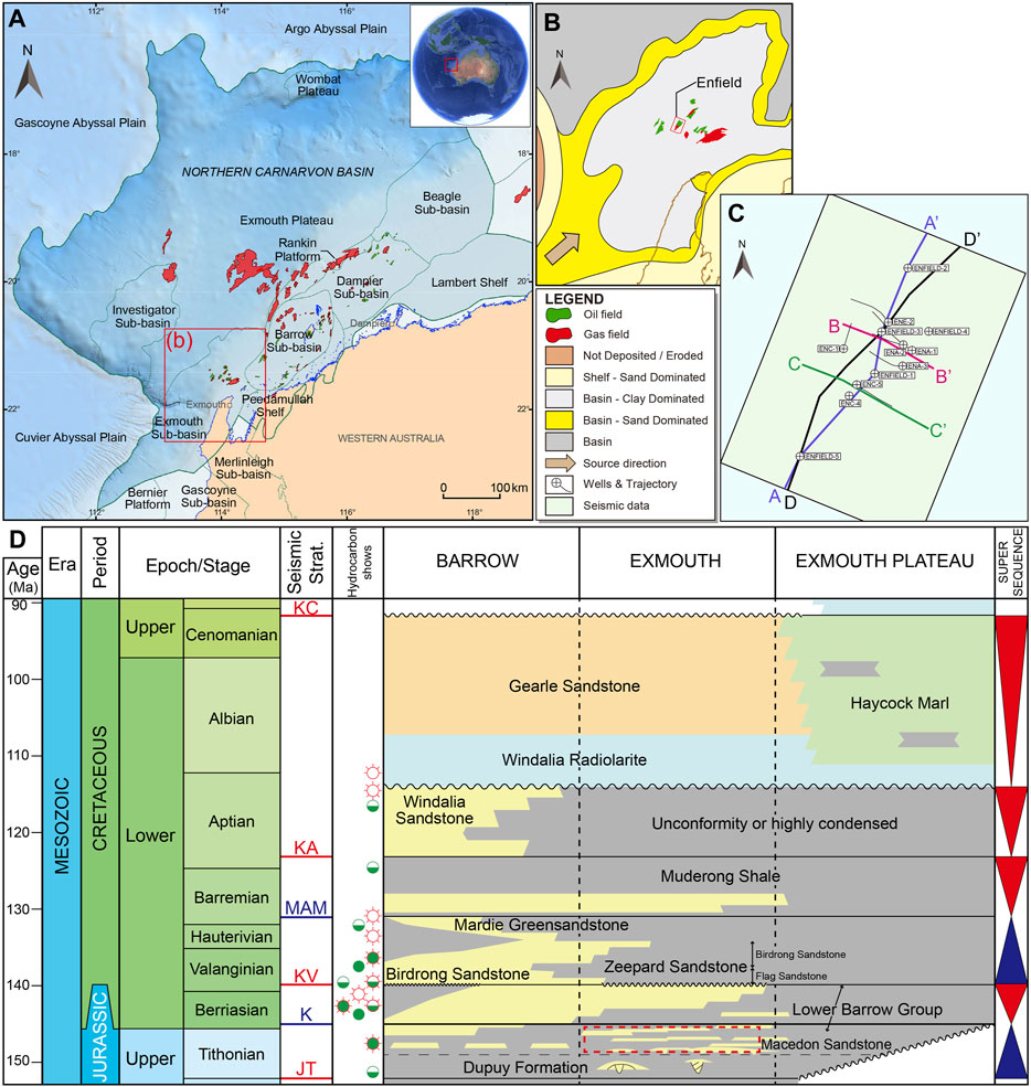
FIGURE 1. (A) The locations and tectonic divisions of the Northern Carnarvon Basin (modified from Australian Government, 2023). (B) The Tithonian paleogeographic maps of the Exmouth sub-Basin in the Northern Carnarvon Basin (modified from Longley et al., 2002). (C) Map showing details of well locations, seismic sections in the Enfield field. (D) Schematic stratigraphic column of the Northern Carnarvon Basin (modified from Australian Government, 2023; Tao et al., 2013).
The stratigraphy of the area is summarized in Figure 1D. During the early to middle Jurassic period, fine-grained deep-water sediments were primarily formed (Arditto et al., 1993; Longley et al., 2002; Tao et al., 2013; Thomas et al., 2020). The Barrow Delta was deposited during the second Early Cretaceous rift period under these conditions. The delta originated from the uplift in the southern part of the Exmouth Sub-basin, associated with the Cape Range Fracture Zone on the southern margin of the Exmouth Plateau (Arditto et al., 1993; Longley et al., 2002; Tao et al., 2013; Thomas et al., 2020).
The Enfield field is mainly composed of the Macedon member sandstone reservoirs. The Macedon member sandstone formed the basal part of the Barrow Group and was deposited during low stand, representing onset of the tectonism. The Macedon member sandstone was initially deposited in a shallow marine shore environment. As sea levels fell, a series of channels developed at topographic lows (such as submarine canyons), leading to the formation of turbidites in deep water (Bussell et al., 2001; Longley et al., 2002; Ementon et al., 2004). These channels, controlled by tectonic activity, were oriented parallel to a series of large-scale northeast-trending terraces (Figure 1B). The Macedon member sandstone was overlain by the Macedon member mudstone, representing the distal mudstone of the northward-advancing Barrow Delta (Figure 1D). Siliciclastic sedimentation continued until the Late Cretaceous, after which a carbonate system gradually formed, persisting to the present day (Figure 1D). This history reflects the dynamic interplay of tectonic forces, sediment deposition, and sea-level changes in shaping the Carnarvon Basin’s complex geological evolution.
A total of 12 wells and a 3D seismic volume were utilized in the study (Figure 1C). Most of the wells have spontaneous potential (SP), gamma rays (GR), sonic (DT), density (DEN), deep laterolog (LLD). Shale volume (Vsh), porosity, and water saturation (Sw) were determined based on these well logs. The study area includes five vertical wells for exploration. The seismic volume used covers approximately 44 km2 of post-stack seismic data. The phase of seismic data was approximately zero, the dominant frequency of seismic data was 40 Hz. The vertical resolution of the seismic data is lower compared to that of the well logs, but it has a relatively higher lateral resolution than spatial interpolation using 1D well data.
The workflow employed for characterizing Macedon turbidite reservoirs in the Enfield field is divided into five main components: (1) seismic interpretation and structural modelling in the study area; (2) geobody extraction using seismic sedimentology; (3) facies modelling based on the results of geobody extraction; (4) porosity inversion using a genetic inversion algorithm; and (5) porosity modelling using sequential Gaussian simulation geostatistical method and co-Kriging method with the porosity inversion results (Azevedo and Soares, 2017). Figure 2 illustrates the workflow implemented in this study.
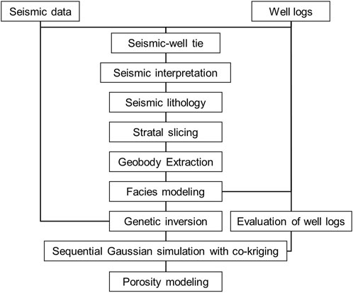
FIGURE 2. The summary of the workflow for the characterization of the turbidite reservoir and the type of data used in the interpretation.
In the seismic interpretation section, the bottom of the Macedon member mudstone and the unconformity surfaces of the Macedon member sandstone in the Enfield field were interpreted together with faults for structural modelling of the Macedon member. This model was then used as an input for subsequent facies and porosity modelling.
In the second part of the workflow, a 90° phase adjustment, stratal slicing mapping tool, and geobody extraction techniques were utilized. The 90° phase adjustment and stratal slicing are among the main techniques used in seismic sedimentology (Zeng et al., 2005a; 2005b). The purpose of the 90° phase adjustment was to establish a correlation between sandstone beds and seismic events, which enables accurate interpretation. Seismic stratal slices with different seismic attributes were then created based on seismic interpretation and the 90° phase adjustment, allowing for high-resolution interpretation of turbidite sand bodies from the 3D seismic volume. The top of the Macedon member served as the reference surface for stratal slicing. Geobody extraction was achieved through seismic sedimentology by performing fusion analysis of multiple seismic attributes and filtering out background signals to extract the target sand bodies (Chaves et al., 2011). This process reduced the ambiguity of individual seismic attributes. The 3D seismic probe was constructed at the target layer location, and the 90° phase adjustment seismic amplitude attribute was overlaid with the sweetness attribute to identify amplitude anomalies and automatically extract geobody. In the subsequent third part, geobody was used as a constraint for the turbidite sand body facies modelling.
Genetic inversion was mainly used to obtain attributes related to the acoustic impedance by analyzing the nonlinear relationships between well log and seismic data (Veeken et al., 2009). Genetic inversion is fast, with low error rates, and is useful for predicting petrophysical properties of reservoirs (Samakinde et al., 2020). We applied the genetic inversion workflow given by Veeken et al. (2009), using the porosity data obtained from well logging (Figure 8) and 90° phase adjustment seismic data as input in this study. Unlike the traditional zero-phase seismic data as input, the 90° phase adjustment seismic data, which has better correlation with the lithology, can better reflect the porosity changes. The well logging data had a higher resolution than the seismic data, thus the original porosity data was initially smoothed to a small extent. The target inversion area was the Macedon member sandstone. Smoothed porosity well logging data trained the neural network, which inverted seismic data into a porosity volume. The genetic inversion parameters were as follows: a time window of 25 ms, a maximum number of 10,000 iterations, a correlation threshold of 0.95, and five neural network hidden layers. The 25 ms time window was close to the seismic wavelet length, and the five neural network hidden layers ensured that the neural network was not overfitted, which leaded to faster as well as better acoustic impedance inversion results (Veeken et al., 2009). The time-domain porosity volume obtained from the genetic inversion was computed from the velocity model to obtain the depth-domain porosity volume. The genetic inversion porosity volume in the study area also providesd a basis for subsequent reservoir porosity modeling.
Finally, porosity modelling was conducted by utilizing porosity from well logging. These porosity logs were then transformed into Gaussian distributions, serving as sample points. Subsequently, a Gaussian variation function model was developed based on these samples. By conducting numerous experiments and analysing the distribution characteristics of turbidite sand bodies, it was determined that the direction with the lowest variability is SW-NE. This direction was oriented parallel to the regional rift fault direction of the Exmouth sub-basin. Conversely, the direction with the highest variability was NW-SE. To achieve Enfield field turbidite sandstone porosity modelling, sequential gaussian simulation was combined with the Co-Kriging method (Ementon et al., 2004). In this process, the 3D porosity inversion volume was employed as a secondary variable.
A comprehensive seismic interpretation consisted of identifying the upper boundary of the Macedon member sandstone, the unconformity surface at the lower boundary of the same, and the primary faults in the Enfield field. The seismic profile in Figure 3A displays these reflectors. The reflector representing the upper boundary of the Macedon member sandstone (indicated by the yellow line in Figure 3B) is primarily characterized by its consistent lateral continuity and negative values of amplitude. Furthermore, this reflector is identified by a typical downlap pattern above it, accompanied by localized truncation on it. The reflector associated with the unconformity surface at the lower boundary of the Macedon member sandstone displays erosive features (indicated by the blue line in Figure 3B). It demonstrated lateral discontinuity and localized truncation characteristics, signifying the erosion and impact of the river channel on the underlying layers. The seismic events within the study interval consisted primarily of high continuity and peak amplitude. The reflector properties of the Macedon member sandstone also provided insight into the sedimentation characteristics during the low-stand system tract.
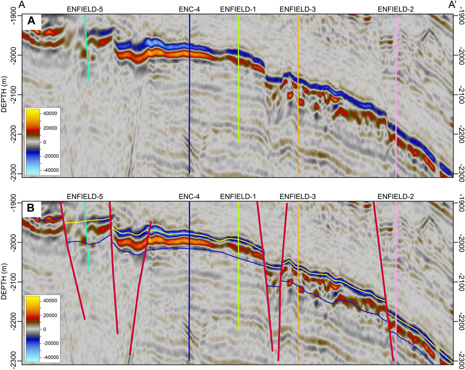
FIGURE 3. Seismic section AA’ (see Figure 1C for line location section) (A) uninterpreted and (B) interpreted.
Following the interpretation of seismic data, a structural modeling and grid were generated, as depicted in Figure 4C. The upper surface of the model displays a significant inclination towards the northeast, aligning with the depocenter of the Exmouth Sub-basin (Figure 4A). The Enfield field features well-developed faults, with normal faults being the most prevalent (Figure 4B). It is the typical complex fault block reservoirs (Figure 4C). In the study area, there are five primary rift faults (Figure 4B), one of which is oriented in an east-west direction (EE’), while the other four are oriented north-south. Of the four, one was situated to the east (AA’), one to the west (DD’), and two in the middle (BB’ and CC’) whose dip angles are opposite, conforming to the conventional southwest-northeast trend of rift faults in the Exmouth Sub-basin. Based on the 4D seismic interpretation (Ali et al., 2008), these five faults which split the Enfield filed into four major structural compartments, were the primary barriers in the study area.
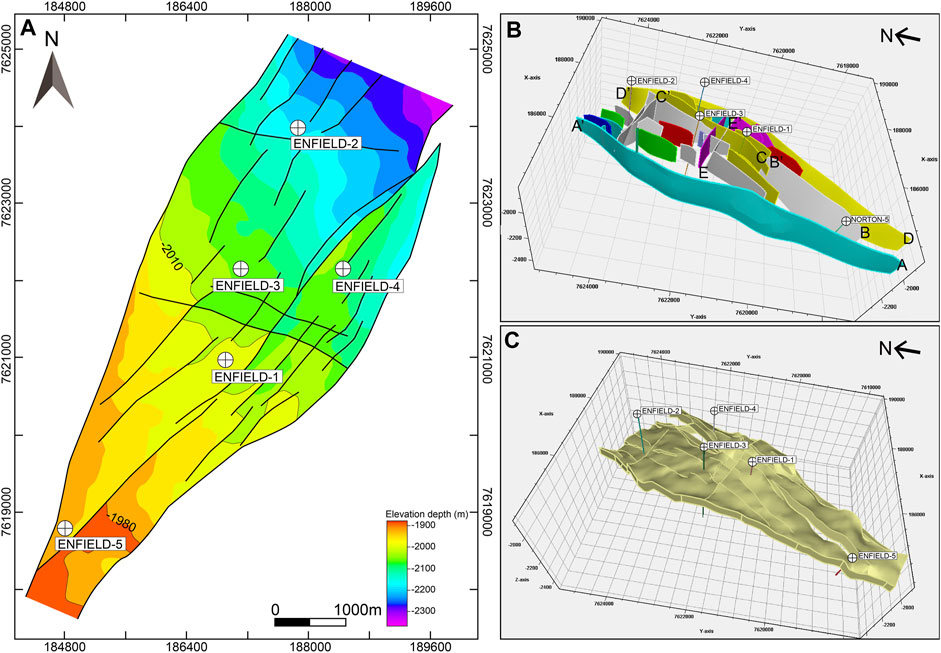
FIGURE 4. The structural characteristics of Enfield field. (A) The structure map of the top of Macedon member sandstone for the area. (B) 3D view of the fault model for the area. (C) 3D view of the structure model for the area.
Rock physics analysis is essential for seismic lithology modelling. When there is a significant contrast in sand-mud impedance, the 90° phase adjustment technique improves the correlation between lithology logging and seismic amplitudes, effectively characterizing lithology variations (Zeng et al., 2005a; 2005b). In a zero-phase seismic section, the amplitude does not directly indicate the presence of sandstone. For instance, in seismic data with low-impedance sand and negatively polarized zero-phase, the top of the sand is typically calibrated at the seismic trough, which makes it less suitable for sandstone interpretation. In the studied interval, the correlation between sandstone intervals based on the low gamma ray logging and seismic events in zero-phase sections was poor. In Figures 5A1, B1, the upper and lower halves of the sandstone correspond to the trough amplitudes (blue) and peak amplitudes (red) in seismic sections, respectively. By applying the 90° phase adjustment to the seismic data, the correspondence between seismic events and sandstone was improved, with the top of the sandstone calibrated at zero phase and the sandstone fully corresponding to the peak, as shown in Figures 5A2, B2. In the flattened well section (Figure 5C), the sandstone closely matches the seismic peak (blue), while the mudstone closely matches the seismic trough (red). In this study, the 90° phase adjustment seismic reflection events can be used to interpret lithology units of turbidite sandstone in the Enfield filed.
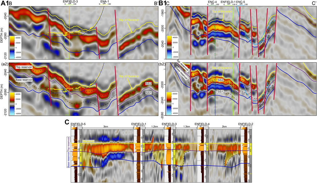
FIGURE 5. Well and Seismic sections demonstrates the relationship between seismic events and lithology. The sands are well tied to seismic peak on the 90°-phase adjustment section. The black dash lines show the position of stratal slices. (A1) Original zero-phase seismic section BB’; (A2) 90°-phase adjustment seismic section BB’; (B1) Original zero-phase seismic section CC’; (B2) 90°-phase adjustment seismic section CC’; (C) Flattened well section on the top of the Macedon member and the sandstone is represented as yellow area. (see Figure 1C for line location section).
Based on the alignment of seismic reflection events with lithology logging, the analysis focuses on the variation in sandstone thickness and the lateral continuity change of seismic events (Figure 5C). The Macedon member sandstone is divided vertically into top and base reservoirs (Figure 5). The top reservoir demonstrates strong lateral continuity and a layered development pattern (Figures 5A1, B1), while the base reservoir shows poor lateral continuity, only developing locally with an erosional-fill pattern (Figures 5A2, B2).
Stratal slicing is a key technique for predicting sedimentary facies in seismic sedimentology (Zeng et al., 2012). Compared to traditional seismic interpretation of sand bodies, this technology offers certain advantages. The selection of stratal slicing methods primarily relies on the geological and structural characteristics of the study area. Currently, three methods are employed: time slicing, horizon slicing, and proportional slicing. Time slicing is appropriate for layered sand bodies and flat formations, but it does not consider variations in sedimentation rate over time and location. Horizon slicing is utilized for layered formations that are not flat. Proportional slicing considers changes in stratal thickness and sedimentation rate (Zeng et al., 2007), offering clear advantages over the first two methods, and it is a commonly used method in seismic sedimentology research. Given the intricate structure of the study area, this study employed the proportional slicing method for stratal slicing. Additionally, the extraction of various seismic attributes is also a commonly employed technique. Besides the results of the 90° phase adjustment, this study further extracted sweetness attributes. The sweetness attribute was derived from the combination of envelope amplitude and instantaneous frequency, making it particularly applicable in deep water clastic rock environments where there are significant acoustic impedance contrasts between sand and shale (Hart et al., 2008). Furthermore, the sweetness attribute can provide a semi-quantitative characterization of the net to gross ratio of the sand body (Hart et al., 2008).
Using the proportional slicing method, we constructed two stratal slices in the study area (Figure 5) to analyze the sedimentary evolution history and sand body distribution characteristics of Macedon member turbidite. Stratal slices SS1 and SS2 (Figure 5) represent the top and base reservoirs sedimentary periods, respectively. The stratal slices (SS1 and SS2) showed significant overlap between the amplitude of the 90° phase adjustment and the sweetness attribute. By combining lithological results from natural gamma rays, high to medium amplitude and high sweetness attribute values correspond to turbidite sand (Figure 6). Conversely, the blue amplitude and lower sweetness attribute values displayed on seismic slices corresponds to the shale or other fine-grained sediments (Figure 6). These non-reservoir sediments exhibited high gamma ray response in most wells. The results of stratal slicing reveal that the Macedon member sandstone developed two distinct sedimentary systems.
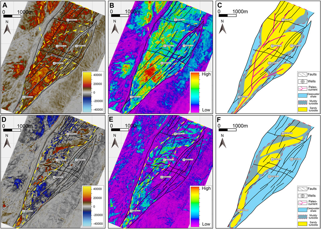
FIGURE 6. Seismic stratal slices illustrating the evolution of turbidite depositional systems. (A–C) the turbidite-fed sand bodies of top reservoir. (D–F) the turbidite-fed sand bodies of base reservoir. The red amplitude matches with sandstone and the black amplitude matches with mudstones in (A,D). The (B,E) are sweetness slices that clearly suggest lithology variations through the amplitude variations and the low-amplitude intervals are typically interpreted as mudstone units, the high-amplitude reflections are commonly interpreted as channel fills. (The position of the slices on vertical seismic section are shown in Figure 5).
The seismic attributes of SS1 associated with the base reservoir exhibit a zone of high to moderate amplitude and high sweetness value in the northeast direction (Figures 6D, E). This zone extended in a direction consistent with the main fault direction in the Exmouth Sub-basin. The turbidite sand body formed during this sedimentary period has a width range of 500 m–1,000 m and gradually becomes fan-shaped at the end (Figure 6F).
The seismic attributes of SS2 show that Enfield field is characterized by widespread high amplitude and high sweetness values (Figures 6A, B). The turbidite sand bodies in the top reservoir are distributed in a sheet-like pattern, with a concentration primarily within the AA’ and DD’ fault range (Figure 6C).
Geobody is employed to describe the spatial distribution range of sand body or other target bodies. The extraction of geo-bodies creates probe bodies within 3D seismic data, which are then utilized in conjunction with 3D perspective rendering technology. Through the fusion and analysis of multiple seismic attributes, it maximizes the distinctive features of various lithofacies in terms of frequency, amplitude, and phase. This enables the identification and classification of seismic facies (abnormal geological bodies), thereby offering an initial comprehension of lithofacies modeling (Chaves et al., 2011). Geobody extraction formed the basis for further studies on the distribution of sedimentary facies.
Figures 7A, C display turbidite geobody outcomes obtained by utilizing high amplitude anomalies as seeds. The geo-body corresponding to the base reservoir is in a channel pattern (Figure 7C), while the geobody corresponding to the top reservoir is in a sheet-like pattern (Figure 7A), consistent with the characteristics revealed by the stratal slice interpretation. Subsequently, the extracted geobodies were sampled into the model grid.
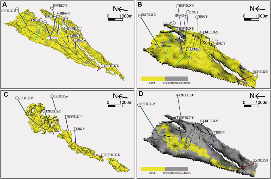
FIGURE 7. Geobodies extracted from seismic attributes and the facies model built through geobody. (A,B) 3D view of turbidite sand geometry and facies model of top reservoir; (C,D) 3D view of turbidite sand geometry and facies model of base reservoir.
The facies and net to pay intervals are determined through well logging, as demonstrated in ENFIELD-3 (Figure 8A) and ENA-1 wells (Figure 8B). The interpretation of well logging results reveals the presence of thin beds of high shale volume and low porosity shale interlayers within the Macedon member sandstone. By combining the sedimentary facies model obtained from geobody with the facies identified through well logging interpretation, we employed the sequential indicator simulation geostatistics method to construct the distribution of shale interlayers within the turbidite sand body. This process yielded the final sedimentary facies models (Figures 7B, D). The application of geobody in facies modeling allowed for the integration of hard data from wells and soft data from seismic surveys.
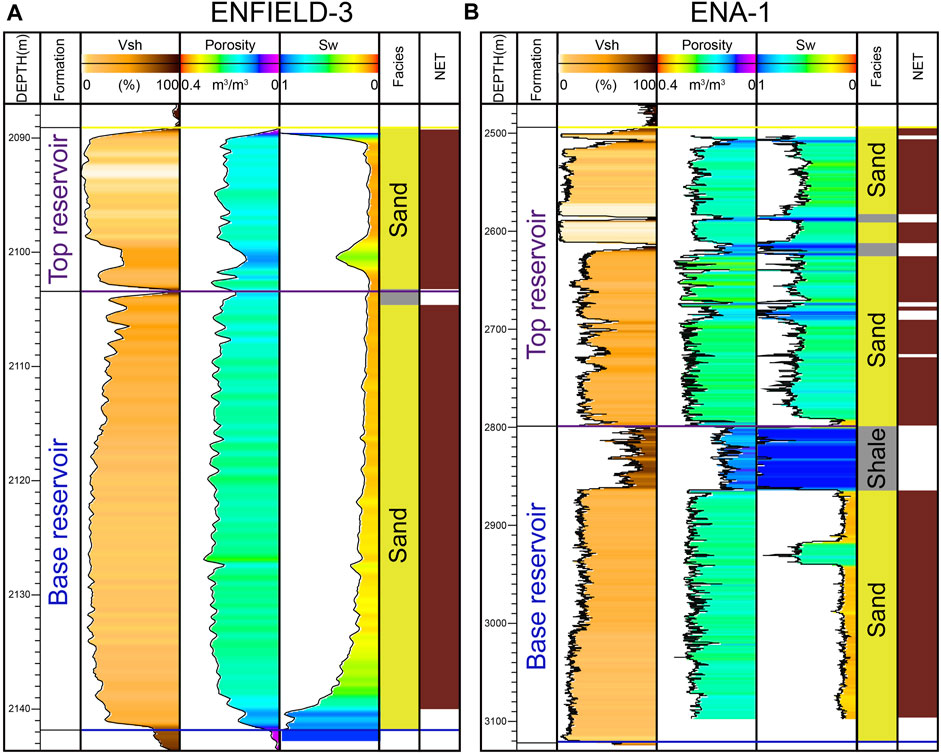
FIGURE 8. Logs evaluation in well ENFIELD-3 (A) and ENA-1 (B). Track 1: depth in meters; Track 2: Formation interval; Track 3: shale volume (Vsh); Track 4: porosity; Track 5: water saturation (Sw); Track 6: lithological log(Facies); Track 7: net-pay intervals.
Genetic inversion is a seismic inversion technique that combines neural network algorithm and genetic algorithm. It was characterized by fast computation, low error, and the ability to invert seismic data to any geophysical attribute related to seismic reflectivity using nonlinear operators in combination with conventional logging data (Veeken et al., 2009). The genetic inversion results at well locations are shown in Figure 9. The well logging porosity has a good correlation with the genetic inversion porosity in the target study interval (Figure 9A). In addition, the intersection plot shows that the correlation between genetic inversion porosity and well logging porosity is 0.84 (Figure 9B), which proves that the genetic inversion results are dependable. The seismic section along the direction of channel is shown in Figure 10. The distribution of genetic inversion porosity (Figure 10B) and 90° phase adjustment seismic amplitude values (Figure 10A) show a clear correlation. Red amplitudes correspond to relative higher porosity, while blue amplitude values correspond to lower porosity (Figure 10B). The Macedon member sandstone is surrounded by shales with low porosity (0 m3/m3 to 0.15 m3/m3), while its interior exhibits medium to high porosity (0.15 m3/m3 to 0.4 m3/m3) (Figure 10B). However, the interior of the Macedon member turbidite reservoir locally exhibits low porosity (Figure 10B). The first type of low porosity occurs between the top reservoir and the base reservoir (Figure 10). This is due to the presence of low energy shale interlayers formed after the deposition of the base reservoir, caused by a temporary rise in sea level. These shale interlayers were only locally developed due to erosion during the deposition of the top reservoir. The second type of low porosity is located within the reservoir (Figure 10) and exhibits locally moderate amplitude values in the 90° phase adjustment seismic section, which is characterized by high-frequency sand-mud interbedding as interpreted from horizontal well logging, suggesting a lateral discontinuity (Figures 5A2, B2). Its genesis may be the formation of shale-filled deposits after small-scale erosion during the late depositional period. The development of these argillaceous interlayers, which typically act as seepage barriers for hydrocarbons, greatly enhances the heterogeneity within the turbidite reservoir. In addition, we have also generated thickness maps of the shale interlayers in the top and base reservoirs to better illustrate the vertical variations in reservoirs across different sedimentary environments (Figure 11). Overall, the base reservoir is more developed than the top reservoir in terms of shale interlayers. The thickness of the former is mainly concentrated in 15 m–24 m (Figure 11A), while the thickness of the latter is mainly concentrated in 0 m–9 m (Figure 11B). The longer distance of sediment transportation resulted in lower sand/mud ratio in the base reservoir, forming a thicker shale interlayer.
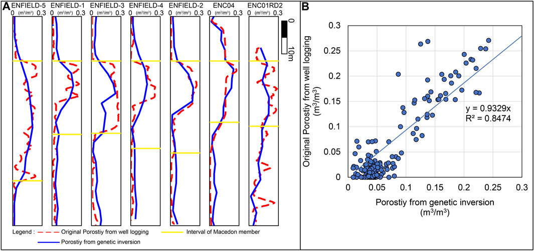
FIGURE 9. (A) Comparison between the original porosity from well logging (red dash line) and the porosity from the seismic genetic inversion (blue line) at well locations. (B) Correlation between the original porosity from well logging and the porosity from the seismic genetic inversion.
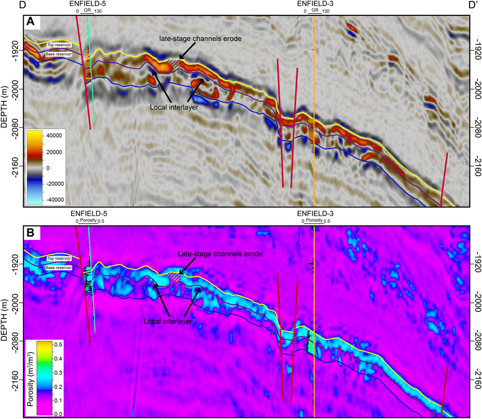
FIGURE 10. (A) 90° phase adjustment seismic section DD’. (B) Porosity section DD’. (see Figure 1C for line location section).
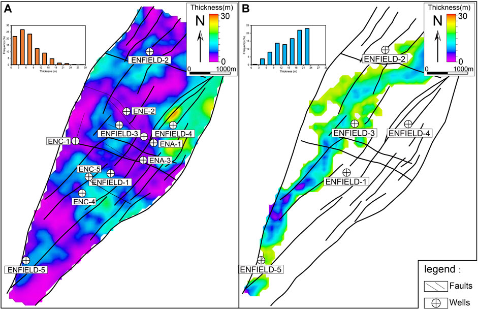
FIGURE 11. The shale interlayer thickness of top reservoir (A) and base reservoir (B).
Porosity modeling was crucial for reservoir characterization as it is closely related to permeability modeling, saturation modeling, and other geologic property modeling (Ma, 2019). Based on the well logging interpretation to obtain the porosity at the well location (Figure 8), the genetic inversion porosity volume was used as the second variable in co-kriging, and the facies model was used as the constraint to simulate the porosity distribution through the sequential gaussian simulation geostatistic method (Figure 12). Further combined with water saturation logging interpretation and the oil-water contact around −2165 m (Medd et al., 2020; Thomas et al., 2020), the effective reservoir distribution in the Enfield field was clarified (Figure 13).
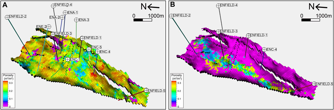
FIGURE 12. Porosity modeling results using the Sequential Gaussian Simulation method with co-kriging. (A) Porosity model of top reservoir; (B) Porosity model of base reservoir.
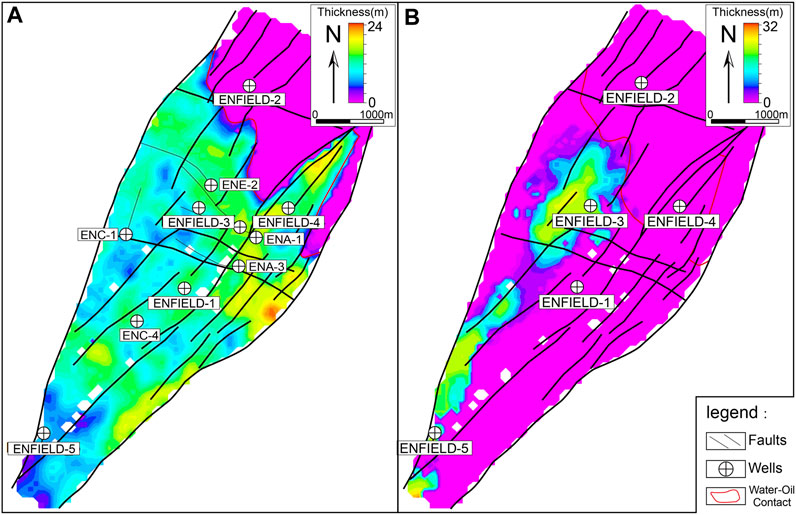
FIGURE 13. The effective reservoir thickness of top reservoir (A) and base reservoir (B).
Figures 12A, 13A represent the porosity model and net reservoir thickness map of the top reservoir, respectively. The porosity ranges from 15% to 30%, with an average of 24%, while the net thickness reaches up to 24 m. It is evident that the main horizontal production wells were drilled through zones with high porosity and net thickness (Figure 13A). Some of the initial exploratory wells, like ENFIELD-2, were non-commercial due to their location below the oil-water contact. The distribution of the base reservoir is influenced by the sand distribution, as shown in Figures 12B, 13B. The porosity ranges from 10% to 28%, with an average of 20%, and the net thickness reach up to 30 m. Overall, the top reservoir exhibited better reservoir properties compared to the base reservoir, and the thinner shale interlayer displayed better reservoir properties. Additionally, in the base reservoir, relatively higher porosity and net thicknesses were primarily found in the narrower upstream section of the channel. In the downstream section of the channel, the seismic section reveals moderate amplitude and low inversion porosity (Figure 10). As shown in Figure 11, this could be attributed to the downstream channel lower energy environment and wider width, resulting in increased shale volume and reduced reservoir quality. The relatively poorer reservoir property, thicker shale interlayers, and smaller oil-bearing areas have prevented the base reservoir from achieving efficient development (Figure 13B).
By applying geobody extraction and conducting a 3D characterization of the Enfield reservoir, we have gained a deeper understanding of the Macedon member turbidite sedimentary systems, including their types and evolution. The sedimentary characteristics of the Macedon member turbidite system within the Enfield field offer valuable insights into the development of deep-water sedimentary systems and their response to changes in sea level. These findings can enhance our comprehension of the intricate processes that govern the formation of sedimentary systems in deep-water environments.
As previously mentioned, the Macedon member sandstone deposited during a period of low sea level. Based on the morphology and distribution of sand bodies, it can be divided into two distinct sedimentary systems: the base reservoir is the confined, channelized turbidite, the top reservoir is the unconfined, amalgamated turbidite sheet (Figure 14).
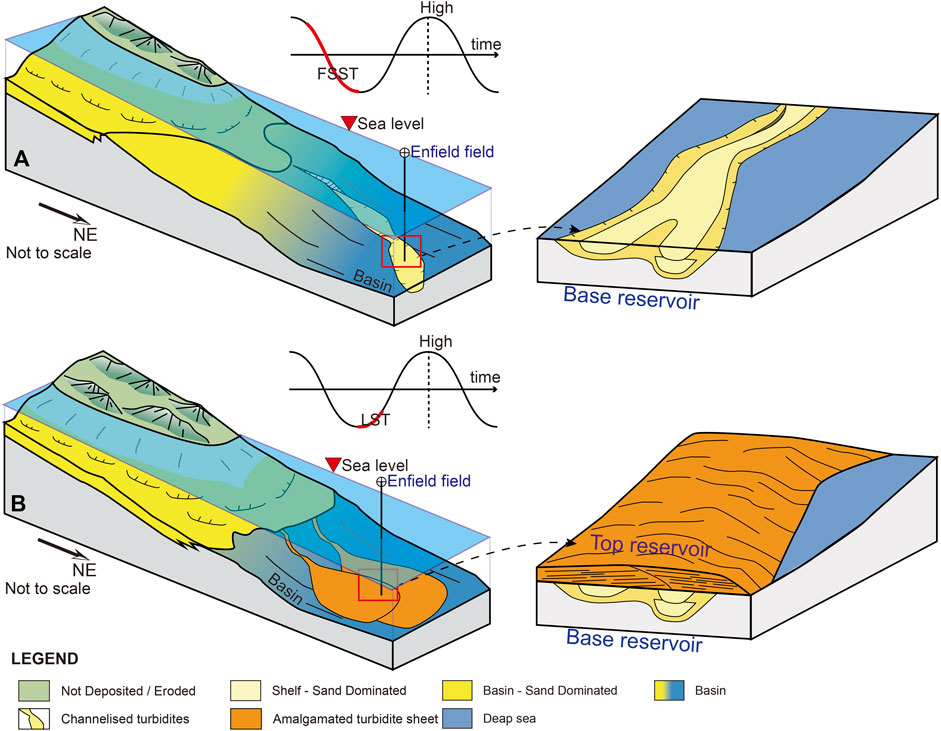
FIGURE 14. Schematic geological model for sedimentary facies of turbidite. (A) Turbidite geological model of base reservoir during the Falling-Ftage Systems Tract (FSST). (B) Turbidite geological model of top reservoir during the Lowstand Systems Tract (LST).
Previous research has suggested various methods for dividing sequences (Vail, 1987; Hunt and Tucker, 1992; Embry and Johannessen, 1993; Catuneanu et al., 2009; Catuneanu et al., 2012). In this study, we utilized the Model independent platform of sequence stratigraphy introduced by Catuneanu et al. (2009). This method incorporates four distinct systems tracts: the falling stage systems tract (FSST), the low stand systems tract (LST), the transitional systems tract (TST), and the high stand systems tract (HST). The development style of sand bodies and reservoir quality in the research area was influenced by changes in sea level. In contrast to the deep-water sequences documented by Posamentier and Kolla (2003), a rapid decline in relative sea level during the early FSST, resulting in limited accommodation. Consequently, sediment deposition did not occur during this time, and narrow banded channels were primarily formed through erosion. Towards the later stage of FSST, the decline in relative sea level slowed down, leading to sufficient sediment supply and the filling of channels with sand. Thus, during the FSST period, sand predominantly formed as the confined, channelized turbidite (Figure 14A). During the LST period, sea level changes tended to stabilize, providing a greater capacity for accommodating substantial amounts of clastic sediments. Moreover, more provenance supply, higher sand/mud ratio, and shorter distance of sediment transportation during the LST period would lead to the deposition of bigger scale turbidite, thus providing high-quality reservoirs. This facilitated the formation of an unconfined, amalgamated turbidite sheet (Figure 14B). As the TST period commenced, relative sea levels experienced a rapid rise, resulting in the capture of a significant volume of sediment in shallow continental shelves. This severed the supply of clastic sediments in the Enfield field and led to the formation of muddy seal.
The proposed a 90° phase adjustment—geobody extraction—genetic inversion joint reservoir characterization workflow outlined in this article proved to be effective in characterizing the Enfield field reservoir. This method successfully characterized geological attributes of the Macedon member turbidite reservoir.
Seismic sedimentology was employed to understand the distribution of sand bodies. By applying a 90° phase adjustment to establish a correlation between seismic events and lithofacies changes, the Macedon member sandstone was divided into a top reservoir and a base reservoir. Analyzing the amplitude and Sweetness changes of the selected stratal slices revealed that the top reservoir demonstrated a sheet-like turbidite pattern, while the base reservoir exhibited a channelized turbidite pattern. Geobody extraction was then utilized to identify and extract these abnormal seismic reflections. By combining geobody extraction with facies interpretation using well logging, geostatistical methods were employed for the facies modeling of the Macedon member turbidite.
Genetic inversion was employed to describe the net reservoir range. By applying a 90° phase adjustment seismic data and interpreting porosity through well logging, a genetic inversion porosity volume was obtained, enabling the modeling of Macedon member sandstone porosity. Overall, the top reservoir shale interlayers had a thickness of 0 m–9 m and a porosity of 15%–30%. The base reservoir shale interlayers had a thickness of 15 m–24 m and a porosity of 10%–28%. The former had better reservoir properties and a larger oil-bearing area, making it the main development layer.
Sea level change was recognized as the main controlling factor for the development style of turbidite in the study area. During the FSST period, confined and channelized turbidites with poor reservoir property were predominantly observed, whereas during the LST period, unconfined and amalgamated turbidite sheets with good reservoir property were primarily formed.
Publicly available datasets were analyzed in this study. This data can be found here: https://www.ga.gov.au/nopims.
YS: Writing–original draft. TY: Conceptualization, Software, Writing–review and editing. YW: Supervision, Writing–review and editing. HX: Writing–review and editing. YZ: Writing–review and editing. QL: Software, Writing–review and editing. YZ: Software, Writing–review and editing.
The authors declare that this study received funding from Petrochina key core technology research and development project 2023ZG18 and Beijing Zhongyou Ruisi Technology Development Co., Ltd. research project 2023FW01603. The funders were not involved in the study design, collection, analysis, interpretation of data, the writing of this article, or the decision to submit it for publication.
We are grateful to SLB for providing support for software such as Petrel. We also appreciate the detailed comments and suggestions by the editor YZ and two reviewers, VT and SK. Additionally, we are grateful for Yajie Tian’s assistance in revising manuscript.
Authors YS, YW, HX, and YuZ were employed by China Research Institute of Petroleum Exploration and Development, China National Petroleum Corporation. Authors TY, QL, and YaZ were employed by Digital & Integration, SLB.
All claims expressed in this article are solely those of the authors and do not necessarily represent those of their affiliated organizations, or those of the publisher, the editors and the reviewers. Any product that may be evaluated in this article, or claim that may be made by its manufacturer, is not guaranteed or endorsed by the publisher.
Ali, A., Taggart, I., Mee, B., Smith, M., Gerhardt, A., and Bourdon, L. (2008). “Integrating 4D seismic data with production related effects at Enfield, north west shelf, Australia,” in SPE Asia Pacific Oil and Gas Conference and Exhibition, Perth, Australia, October, 2008.
Arditto, P. (1993). Depositional sequence model for the post-barrow group neocomian succession, barrow and exmouth sub-basins, western Australia. APPEA J. 33, 151. doi:10.1071/AJ92012
Australian Government, (2023). Carnarvon Basin. https://www.ga.gov.au/scientific-topics/energy/province-sedimentary-basin-geology/petroleum/offshore-northwest-australia/canarvon (Accessed August 29, 2023).
Azevedo, L., and Soares, A. (2017). “Introduction—geostatistical methods for integrating seismic reflection data into subsurface Earth models,” in Geostatistical methods for reservoir geophysics. Editors L. Azevedo, and A. Soares (Cham, Germany: Springer International Publishing), 1–3.
Barbosa, G. S., Pena dos Reis, R., Garcia, A. J. V., Barberes, G. d.A., and Garcia, G. G. (2022). Petroleum systems analysis of turbidite reservoirs in rift and passive margin atlantic basins (Brazil and Portugal). Energies 15 (21), 8224. doi:10.3390/en15218224
Bussell, M. R., Jablonski, D., Enman, T., Wilson, M. J., and Bint, A. N. (2001). Deepwater exploration: north western Australia compared with gulf of Mexico and Mauritania. APPEA J. 41 (1), 289–320. doi:10.1071/AJ00014
Catuneanu, O., Abreu, V., Bhattacharya, J. P., Blum, M. D., Dalrymple, R. W., Eriksson, P. G., et al. (2009). Towards the standardization of sequence stratigraphy. Earth-Science Rev. 92 (1), 1–33. doi:10.1016/j.earscirev.2008.10.003
Catuneanu, O., Martins-Neto, M. A., and Eriksson, P. G. (2012). Sequence stratigraphic framework and application to the Precambrian. Mar. Petroleum Geol. 33 (1), 26–33. doi:10.1016/j.marpetgeo.2010.10.002
Chaves, M. U., Marco, L. D., Kawakami, G., and Oliver, F. (2011). “Visualization of geological features using seismic volume rendering, RGB blending and geobody extraction,” in 12th International Congress of the Brazilian Geophysical Society & EXPOGEF, Rio de Janeiro, Brazil, August, 2011, 848–850.
Embry, A. F., and Johannessen, E. P. (1993). “T–R sequence stratigraphy, facies analysis and reservoir distribution in the uppermost Triassic–Lower Jurassic succession, western Sverdrup Basin, Arctic Canada,” in Norwegian petroleum society special publications. T. O. Vorren, E. Bergsager, Ø. A. Dahl-Stamnes, E. Holter, B. Johansen, E. Lieet al. (Amsterdam, Netherlands: Elsevier), 121–146.
Ementon, N., Hill, R., Flynn, M., Motta, B., and Sinclair, S. (2004). “Stybarrow oil field - from seismic to production, the integrated story so far,” in SPE Asia Pacific Oil and Gas Conference and Exhibition, Perth, Australia, October, 2008.
Fairburn, M., Pedler, H. S., and Louis, J. (2022). “Reducing Laverda canyon field production uncertainty with early lifecycle time-lapse 4D seismic data,” in SPE Asia Pacific Oil & Gas Conference and Exhibition, Adelaide, Australia, October, 2022.
Feng, Y., Jiang, S., Hu, S., Li, S., Lin, C., and Xie, X. (2016). Sequence stratigraphy and importance of syndepositional structural slope-break for architecture of Paleogene syn-rift lacustrine strata, Bohai Bay Basin, E. China. Mar. Petroleum Geol. 69, 183–204. doi:10.1016/j.marpetgeo.2015.10.013
Fisher, R. V. (1983). Flow transformations in sediment gravity flows. Geology 11 (5), 273–274. doi:10.1130/0091-7613
Hart, B. S. (2008). Channel detection in 3-D seismic data using sweetness. AAPG Bull. 92 (6), 733–742. doi:10.1306/02050807127
Hunt, D., and Tucker, M. E. (1992). Stranded parasequences and the forced regressive wedge systems tract: deposition during base-level'fall. Sediment. Geol. 81 (1), 1–9. doi:10.1016/0037-0738(92)90052-S
Longley, I., Buessenschuett, C., Clydsdale, L., Cubitt, C. J., Davis, R., Johnson, M. K., et al. (2002). The North West shelf of Australia - a woodside perspective, the sedimentary basins of western Australia. Proc. West. Aust. Basins Symposium 3, 28–88.
Lou, M., Cai, H., He, X., Liu, Y., Huang, X., Zhang, X., et al. (2023). Application of seismic sedimentology in characterization of fluvial-deltaic reservoirs in Xihu sag, East China Sea shelf basin. Petroleum Explor. Dev. 50 (1), 138–151. doi:10.1016/S1876-3804(22)60375-6
Lowe, D. R. (1982). Sediment gravity flows; II, Depositional models with special reference to the deposits of high-density turbidity currents. J. Sediment. Res. 52 (1), 279–297. doi:10.1306/212f7f31-2b24-11d7-8648000102c1865d
Lutome, M. S., Lin, C., Chunmei, D., Zhang, X., and Harishidayat, D. (2020). Seismic sedimentology of lacustrine delta-fed turbidite systems: implications for paleoenvironment reconstruction and reservoir prediction. Mar. Petroleum Geol. 113, 104159. doi:10.1016/j.marpetgeo.2019.104159
Ma, Y. Z. (2019). “Multiscale heterogeneities in reservoir geology and petrophysical properties,” in Quantitative geosciences: data analytics, geostatistics, reservoir characterization and modeling (Cham, Germany: Springer International Publishing), 175–200.
Mayall, M., and Byrne, C. (2002). “Reservoir prediction and development challenges in turbidite slope channels,” in Proceedings of the Offshore Technology Conference, Houston, Texas, USA, May, 2022.
McCarthy, T. A., and Mickelburgh, I. J. (2010). “The evolution of sand control completion practices for the Enfield deep water development,” in SPE International Symposium and Exhibition on Formation Damage Control, Lafayette, Louisiana, USA, February, 2010.
Medd, D., Thomas, P., Sibbons, C., Smith, M., and Ali, A. (2020). “Integration of 4D seismic to add value: the Enfield ENC01 sidetrack story,” in SPE Asia Pacific Oil and Gas Conference and Exhibition, Brisbane, Queensland, Australia, October, 2020.
Mohsin, M., Tavakoli, V., and Jamalian, A. (2023). The effects of heterogeneity on pressure derived porosity changes in carbonate reservoirs, Mishrif formation in SE Iraq. Petroleum Sci. Technol. 41, 898–915. doi:10.1080/10916466.2022.2070210
Peng, C., Xian, B., Li, M., Fang, L., Rahman, N. U., Liu, J., et al. (2023). Intensified lacustrine turbidite deposition as a response to the carnian pluvial episode: insights from the triassic ordos Basin in north China plate. Palaeogeogr. Palaeoclimatol. Palaeoecol. 623, 111599. doi:10.1016/j.palaeo.2023.111599
Posamentier, H. W., and Kolla, V. (2003). Seismic geomorphology and stratigraphy of depositional elements in deep-water settings. J. Sediment. Res. 73 (3), 367–388. doi:10.1306/111302730367
Ruvo, L., Calderoni, M., Cesaro, M., Fonnesu, F., Franco, I., Lyne, A. M., et al. (2008). “Integrated reservoir petrophysical characterization and 3D modeling: a deep-water turbidite reservoir case study,” in Proceedings of the International Petroleum Technology Conference, Kuala Lumpur, Malaysia, December, 2008.
Samakinde, C. A., Donker, J. M. v.B., and Fadipe, O. A. (2020). A combination of genetic inversion and seismic frequency attributes to delineate reservoir targets in offshore northern Orange Basin, South Africa. Open Geosci. 12 (1), 1158–1168. doi:10.1515/geo-2020-0200
Sinan, S., Glover, P. W. J., and Lorinczi, P. (2020). Modelling the impact of anisotropy on hydrocarbon production in heterogeneous reservoirs. Transp. Porous Media 133, 413–436. doi:10.1007/s11242-020-01430-z
Smith, N., Dempsey, C., Jackson, M., and Preston, J. (2003). Overcoming historical bias: an integrated geological and engineering assessment of the coniston prospect, exmouth sub-basin. APPEA J. 43 (1), 363–383. doi:10.1071/AJ02019
Tao, C., Bai, G., Liu, J., Deng, C., Lu, X., Liu, H., et al. (2013). Mesozoic lithofacies palaeogeography and petroleum prospectivity in North Carnarvon Basin, Australia. J. Palaeogeogr. 2 (1), 81–92. doi:10.3724/SP.J.1261.2013.00019
Thomas, P., Harrowfield, G., Fitzpatrick, J., and Berglin, B. (2020). “A campaign of 4D seismic monitor surveys on Australia's northwest shelf,” in SPE Asia Pacific Oil & Gas Conference and Exhibition, Virtual, November, 2020.
Vail, R. P. (1987). Seismic stratigraphy interpretation using sequence stratigraphy: Part 1: seismic stratigraphy interpretation procedure. AAPG Stud. Geol. 1.
Veeken, P. C. H., Priezzhev, I. I., Shmaryan, L. E., Shteyn, Y. I., Barkov, A. Y., and Ampilov, Y. P. (2009). Nonlinear multitrace genetic inversion applied on seismic data across the Shtokman field, offshore northern Russia. Geophysics 74 (6), WCD49–WCD59. doi:10.1190/1.3223314
Wei, E. A., Holmes, J. J., and Driscoll, N. W. (2020). Strike-slip transpressional uplift offshore san onofre, California inhibits sediment delivery to the deep sea. Front. Earth Sci. 8. doi:10.3389/feart.2020.00051
Weimer, P., and Link, M. H. (1991). “Global petroleum occurrences in submarine fans and turbidite systems,” in Seismic facies and sedimentary processes of submarine fans and turbidite systems. Editors P. Weimer, and M. H. Link (New York, NY, USA: Springer New York), 9–67.
Wu, Q., Xian, B., Gao, X., Bai, Q., Wang, Z., Liu, J., et al. (2022). Differences of sedimentary triggers and depositional architecture of lacustrine turbidites from normal regression to forced regression: eocene Dongying depression, Bohai Bay Basin, East China. Sediment. Geol. 439, 106222. doi:10.1016/j.sedgeo.2022.106222
Zeng, H., and Backus, M. M. (2005a). Interpretive advantages of 90°-phase wavelets: Part 1 — modeling. Geophysics 70 (3), C7–C15. doi:10.1190/1.1925740
Zeng, H., and Backus, M. M. (2005b). Interpretive advantages of 90°-phase wavelets: Part 2 — seismic applications. Geophysics 70 (3), C17–C24. doi:10.1190/1.1925741
Zeng, H., Davies, R. J., Posamentier, H. W., Wood, L. J., and Cartwright, J. A. (2007). “Seismic imaging for seismic geomorphology beyond the seabed: potentials and challenges,” in Seismic geomorphology: applications to hydrocarbon exploration and production (London: Geological Society of London).
Zeng, H., Zhu, X., Zhu, R., and Zhang, Q. (2012). Guidelines for seismic sedimentologic study in non-marine postrift basins. Petroleum Explor. Dev. 39 (3), 295–304. doi:10.1016/S1876-3804(12)60045-7.ss
Zhang, F., Li, J., Xiong, L., Liu, Q., Zhang, W., and Maulana, I. (2021). Turbidite facies identification and analysis using geophysical methods in the salt diapir domain of Lower Congo basin. Mar. Petroleum Geol. 133, 105264. doi:10.1016/j.marpetgeo.2021.105264
Zhang, G., Qu, H., Chen, G., Zhao, C., Zhang, F., Yang, H., et al. (2019). Giant discoveries of oil and gas fields in global deepwaters in the past 40 years and the prospect of exploration. J. Nat. Gas Geoscience 4 (1), 1–28. doi:10.1016/j.jnggs.2019.03.002
Keywords: reservoir characterization, turbidite, seismic sedimentology, geobody extraction, genetic inversion
Citation: Song Y, Yu T, Wang Y, Xiang H, Zhang Y, Li Q and Zhang Y (2023) A workflow for turbidite reservoir characterization—a case study of the Macedon member, Northern Carnarvon Basin, NW Australia. Front. Earth Sci. 11:1308885. doi: 10.3389/feart.2023.1308885
Received: 07 October 2023; Accepted: 22 November 2023;
Published: 29 December 2023.
Edited by:
Yi Zheng, Sun Yat-sen University, ChinaCopyright © 2023 Song, Yu, Wang, Xiang, Zhang, Li and Zhang. This is an open-access article distributed under the terms of the Creative Commons Attribution License (CC BY). The use, distribution or reproduction in other forums is permitted, provided the original author(s) and the copyright owner(s) are credited and that the original publication in this journal is cited, in accordance with accepted academic practice. No use, distribution or reproduction is permitted which does not comply with these terms.
*Correspondence: Yanchen Song, c29uZ3ljMjJAcGV0cm9jaGluYS5jb20uY24=; Ting Yu, dHl1NEBzbGIuY29t
Disclaimer: All claims expressed in this article are solely those of the authors and do not necessarily represent those of their affiliated organizations, or those of the publisher, the editors and the reviewers. Any product that may be evaluated in this article or claim that may be made by its manufacturer is not guaranteed or endorsed by the publisher.
Research integrity at Frontiers
Learn more about the work of our research integrity team to safeguard the quality of each article we publish.