 Changyuan Lu1
 Linxiu Han
94% of researchers rate our articles as excellent or good
Learn more about the work of our research integrity team to safeguard the quality of each article we publish.
Find out more
ORIGINAL RESEARCH article
Front. Earth Sci., 28 December 2023
Sec. Geoinformatics
Volume 11 - 2023 | https://doi.org/10.3389/feart.2023.1308369
This article is part of the Research TopicInstability Mechanisms and Disaster Prevention of Coal and Rock in Deep Underground SpaceView all 12 articles
In order to accurately determine the location of fracture zone, optimize the design parameters of high-level boreholes, and improve the effect of gas drainage, take the No. 25030 working face of Xuehu Coal Mine, Henan Shenhuo Coal & Power Co., Ltd. as the research object to study the movement law of overburden strata in the working face. To determine the height of ‘vertical three zones’ of overburden strata by combining theoretical calculation, numerical simulation and field test. Through theoretical calculation, the maximum vertical height range of caving zone from coal seam roof is 5.5–9.2 m, and the maximum vertical height range of water flowing fractured zone from coal seam roof is 26.0–37.2 m. Through numerical simulation, the maximum height of the caving zone is 8.0 m from the roof, and the maximum height of the fracture zone is 27.0 m from the roof. Through field test, when the vertical height of the final borehole from the roof of the coal seam is 18.4–30.0 m, the gas concentration extracted by the borehole is generally high. When the vertical height of the borehole is 24.6–28.4 m from the coal seam roof, the gas concentration is in the peak area. The height distribution range of rock “vertical three zones” in Xuehu Mine No. 25030 working face obtained by three methods is roughly similar, and it is suggested to refer to the measured value in the design of goaf gas drainage. The test results show that the gas drainage effect is the best when the vertical distance from the coal seam roof is 24.6–28.4 m, and it is suggested that the high level boreholes should be arranged in this area.
Gas drainage represents a fundamental technique for the prevention of gas accidents within coal mines, simultaneously catering to modern requirements for the co-extraction of coal and gas, the utilization of coalbed methane, and the pursuit of environmentally-friendly coal mining practices (Li et al., 2023a; Li et al., 2023b). High-level borehole drainage, a widely employed technique for gas control in mined-out areas, is predicated on positioning the borehole terminus within the gas-enriched area of the fracture zone to maximize the extraction of depressurized gas from adjacent strata and the mined-out areas (Sun et al., 2017; Zhao, 2017). The accurate determination of the fracture zone’s location, the optimization of high-level borehole design parameters, and the enhancement of gas drainage efficiency hold significant practical value, particularly in addressing gas management issues at the working face and ensuring the safety of coal mine operations.
Scholars from home and abroad have extensively studied the movement patterns of overburden disturbed by mining and the strategic placement of high-level boreholes. Researchers including Minggao Qian, Jialin Xu, Liang Yuan, and Shugang Li (Yuan, 2016; Li et al., 2018; Chen et al., 2020; Chen et al., 2022; Liu and Li, 2023) have sequentially introduced classical theories such as the “key layer”, “O-ring”, “horizontal three zones”, “vertical three zones”, “returning ring”, “elliptical belt”, “trapezoidal platform”, among others. Further research by Ju et al. (Gao and Chen, 2016) examined the collapse process of overburden in extraordinarily high longwall faces, building upon the key layer theory. Jianliang Gao et al. (Lv et al., 2019) used CDEM software to identify the distribution of the “vertical three zones” in the mined-out area. Xiaobo Lü and colleagues (Li et al., 2017) pinpointed the top 1618 m of the roof as the location for high-level borehole placement based on observed roof fracture developments. Through numerical simulations paired with the key layer theory, Chunyuan Li and his team (Wang et al., 2019a) identified the layer for high-level gas drilling influenced by roof pressure and the development of macro flow channels. Shuanlin Wang et al. (Pan et al., 2023a) determined that the top 2035 m is the optimal final hole layer for high-level boreholes through the UDEC simulation analysis of overburden displacement and changes in stress parameters. Longhai Zhu (Pan et al., 2023b) conducted a numerical analysis of the developmental rules of overburden’s “three zones”, and by combining theoretical analysis with simulations of gas migration characteristics and analysis of gas influx sources on the working face, eventually ascertained the most suitable borehole placement for high-level drilling. In addition, some researchers used borehole television, ultrasonic penetration, borehole electromagnetic wave CT, and down-hole water injection leak detection (Wang et al., 2019b; Ye et al., 2023a; Ye et al., 2023b; Ma et al., 2023) to explore the damage patterns of overburden on the working face.
These studies demonstrate that methods to ascertain the layer positioning of high-level drilling encompass empirical formula calculation, physical simulation, numerical simulation, and field experiments. Most previous studies have employed a single method, and considering the limitations of each approach, this paper focuses on the 2-25030 working face of Xuehu Coal Mine, Henan Shenhua Group Co., Ltd. The study investigates the movement patterns of the working face’s overburden in the mining field. By integrating theoretical calculations, numerical simulations, and field testing, we determine the height of the “vertical three zones” in the overlying rock layer and identify the gas-rich areas within the fracture zone. This study holds significant practical value, especially in improving the efficiency of gas drainage and ensuring safe mining operations.
Xuehu Coal Mine is located in the northern part of Yongcheng City, Henan Province, and is under the jurisdiction of Yongcheng City. The thickness of the coal seam mined in the 2-25030 working face ranges from 0.6 to 3.7 m, with an average thickness of 2.3 m. The structure of the coal seam is simple, with an inclination of 15°–2° and an average of 10°. The coal seam within the working face area is stable and belongs to the category of simple-structured, medium-thick stable coal seams. The coal is of low quality, mainly bright coal with high hardness, classified as Class II∼III, and structural coal is not developed. The main components of the roof are fine-grained sandstone, mudstone, and carbonaceous mudstone, and the roof management method is to mine the full height at once in a fully caved manner.
Combining the dip angle of the coal seam and the condition of the overlying rock strata in the 2-25030 working face of Xuehu Coal Mine, the maximum heights of the caved zone and the water-conducting fracture zone are preliminarily estimated based on empirical formulas. Taking M as 2.3 m, the maximum height of the caved zone Hc and the maximum height of the water-conducting fracture zone (including the maximum height of the caved zone) Hf are calculated as:
Therefore, according to the empirical formula, it can be preliminarily determined that the maximum vertical height range of the caved zone in the roof of the No. 2 coal seam of Xuehu Coal Mine is 5.59.9 m, and the maximum vertical height range of the water-conducting fracture zone from the roof of the coal seam is 26.037.2 m.
This model, (Figure 1) set against the engineering background of the 2-25030 working face in Xuehu Coal Mine, Henan Shenhuo Coal and Electricity Co., Ltd., is located in the eastern wing of the 25th mining area of the mine. The horizontal elevation is −780 m and the ground elevation is +37.5 m. The composition of the rock layers of the top and bottom of the coal seam is shown in Table 1. Combined with the actual coal-rock distribution of the working face, the physical model size for simulation was determined to be 600 m (length) × 60 m (height). The simulated coal seam is buried at a depth of 817.5 m, and a vertical stress of 20.4 MPa is uniformly applied to the top. The horizontal displacement of the left and right boundaries is set to zero, and the vertical displacement of the lower boundary is set to zero. The Mohr-Coulomb constitutive model is adopted, starting to excavate from the 150 m mark. A coal pillar of 150 m is left at the left boundary to eliminate boundary effects. Each step is excavated by 10 m, and after equilibrium is reached, the next step is excavated. The mechanical parameters of the coal and rock layer models are determined in accordance with the mine geological report, as shown in Table 2.
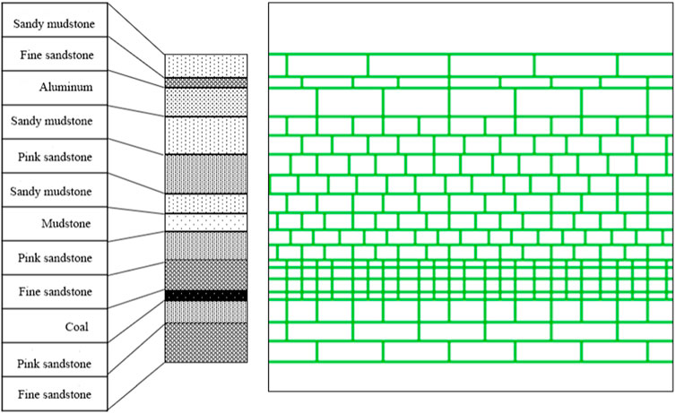
FIGURE 1. Geological Geometric Model of Coal and Rock.
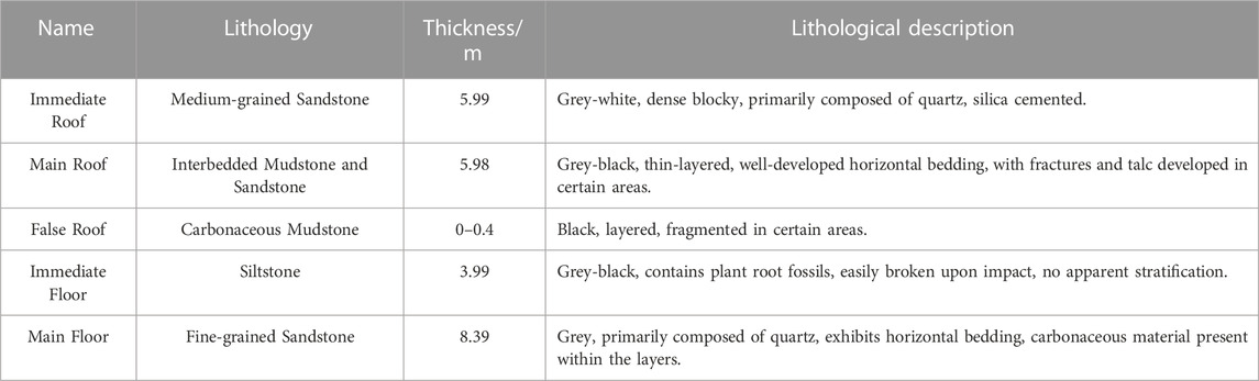
TABLE 1. Composition and lithology of the top and bottom rock layers of the coal seam.

TABLE 2. Mechanical parameters of coal and rock.
From the data of previous backfill mining faces, we find that the range of the initial pressure step of the main roof is 38.8–49.04 m, and the range of the periodic pressure step is 15.8–20.0 m. However, due to the thickness of the immediate roof, the goaf can be filled with gangue after collapse, so the increase in support pressure from the initial and periodic loading of the main roof is not very pronounced. When 50 m of simulated excavation was conducted, the overlying strata of the roof experienced the initial loading phenomenon (Figure 2A). The immediate roof rock, subjected to its own gravity and the squeeze from the rock layer above, gradually collapses into the goaf. Its displacement is largest in the middle of the goaf, reaching 2.0 m. As mining continues, the overlying strata in the goaf undergo a cyclic rupture process of “stable-unstable-re-stable”. After excavating to 200 m, the collapse pattern of the overlying strata in the goaf becomes stable, and the displacement cloud diagram of the overburden presents a trapezoidal distribution, wide at the bottom and narrow at the top. Because the overall displacement rule of the overburden is quite clear, the simulation is no longer continued. The exported displacement vector diagram of the overburden shows that when the initial loading phenomenon occurs, the central part of the overburden in the goaf has the largest subsidence, and the immediate roof almost entirely collapses into the goaf. The displacement on both sides is relatively small due to the support effect of the coal walls. After simulating the excavation of 200 m, the displacement vector of the overburden presents a trapezoidal distribution (Figure 3), wide at the bottom and narrow at the top, with the edge of the overburden in the goaf descending 0.2 m and the middle part sinking 2.1 m.
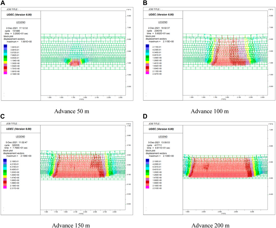
FIGURE 2. Overlying Strata Movement in the Mining Field. (A). Advance 50 m (B). Advance 100 m. (C). Advance 150 m (D). Advance 200 m.
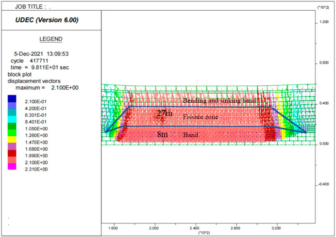
FIGURE 3. Division of the “Vertical Three Zones” in the Overlying Rock.
Upon analyzing the displacement vectors, we find that after the overburden in the goaf becomes stable following the excavation of 200 m, there is a significant decrease in the density of the displacement vectors at heights of 8.0 m and 27.0 m from the roof. After the rocks in the caving zone above the goaf fully settle into the goaf, the rock layers above the caving zone exert pressure on it and then compress and compact it, causing the rocks in the caving zone to arrange tightly. Therefore, the displacement vectors of the rocks in the caving zone are the most densely packed. As for the fracture zone above the caving zone, because its own subsidence is less than that of the caving zone, the length of the displacement vector in the fracture zone is shorter than that of the caving zone, and the pressure on the rock layer is lighter than that of the caving zone. Therefore, in the vector diagram, it is manifested as a smaller displacement vector density. Similarly, the displacement vector density of the rock layer in the bending subsidence zone is the smallest. According to the vector density in the overburden subsidence vector diagram, there is a pattern in the overburden subsidence vectors in the diagram, where the vector density changes significantly at two heights. This should be regarded as the dividing lines of the “vertical three zones” in the overburden of the goaf. That is, the maximum height of the caving zone is 8.0 m from the roof, the maximum height of the fracture zone is 27.0 m from the roof, and the division of the “vertical three zones” in the overburden of the goaf is shown in Figure 3.
Common methods for field inspection of the height of the “vertical three zones” in the mining field overburden include the borehole water injection method, borehole gas injection method, roof observation method, borehole television method, etc. In this study, the borehole drainage effect inspection method was selected.
Generally speaking, the entire extraction process of high-level drilling is divided into three stages [21]: 1) As shown in Figure 4A, when the end hole of the drilling falls near the top of the mining face, gas extraction from the goaf begins. During the process of advancing the working face to Figure 4B, the gas extraction concentration and flow rate are constantly increasing. At this time, it is in the intensification stage of gas extraction, and the gas extraction efficiency will reach its maximum in this process. 2) As the mining face continues to move forward, the end hole location gradually enters the compaction zone. As shown in Figure 4C, the gas storage and spatial position are not conducive to gas extraction, and the gas extraction concentration and flow rate begin to decline. This stage is the decay stage of gas extraction. 3) As the goaf continues to move towards the drilling field, the end hole location has completely fallen into the compaction zone (Figure 4D), and the borehole gradually approaches the caving zone of the goaf, leading to borehole collapse and failure. At this stage, the borehole has completely failed.
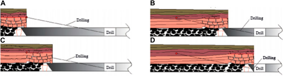
FIGURE 4. Schematic of high-level drilling with coal body mining.
Under normal circumstances, the concentration and extraction volume of borehole gas extraction depend on the sealing quality of the borehole, the negative pressure of extraction at the borehole, and the location of the borehole (Figure 5). When the quality of borehole sealing and the negative pressure of extraction at the borehole are constant, the mixed volume (concentration) of gas extraction from high-level drilling varies with the location of the end hole of the drilling in the shape of a parabolic curve. That is, when the extraction starts, the mixed volume and concentration of the extracted gas are small. This is because the coal (rock) layer around the high-level drilling has not yet been unloaded, and the gas in the neighboring layer has not been desorbed. As the working face gradually advances, the coal (rock) layer around the high-level drilling is fully unloaded, and the extraction concentration and mixed volume gradually increase to the highest, indicating that the borehole has entered the fracture zone. After a period of stable extraction, it begins to decline, which is due to the high-level borehole gradually entering the caving zone and sucking in air and the decrease of the unloaded gas source in the neighboring layer. Therefore, the height of the caving zone is analyzed and determined according to the initial extraction section, high extraction volume section, and attenuation section during the extraction process, thereby providing a basis for optimizing drilling parameters.
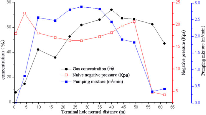
FIGURE 5. Change curves of borehole gas concentration, extraction negative pressure, and extraction volume.
To investigate the height of the “vertical three zones” in the overburden layer of the mining field, 4 sets of high-level boreholes with different end-hole heights were designed and constructed in the 25030 air lane, as shown in Figure 6. The high-level borehole construction was conducted on the roof at the junction of the coal wall and the roof in the lower side of the air lane. Each group of high-level boreholes was drilled with 8 boreholes, with a hole spacing of 0.7 m, a hole depth of 55–57 m, a high-level hole group spacing of 15 m, and the end hole locations were 20 m, 25 m, 30 m, and 35 m away from the coal seam roof, respectively.
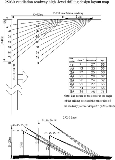
FIGURE 6. Schematic Diagram of High-level Borehole Construction Design.
The extraction effect of each group of high-level boreholes was investigated on-site, and the data during borehole extraction was organized to draw the change curves of borehole extraction volume and gas concentration. Among them, 35-2#, 35-8#, and 30-4# are shown in Figures 7–9 respectively.
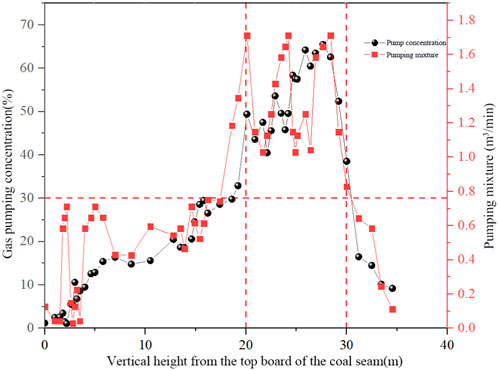
FIGURE 7. Change curves of gas concentration and extraction volume of 35-2# borehole.
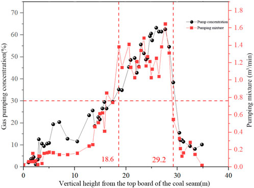
FIGURE 8. Change curves of gas concentration and extraction volume of 35-8# borehole.
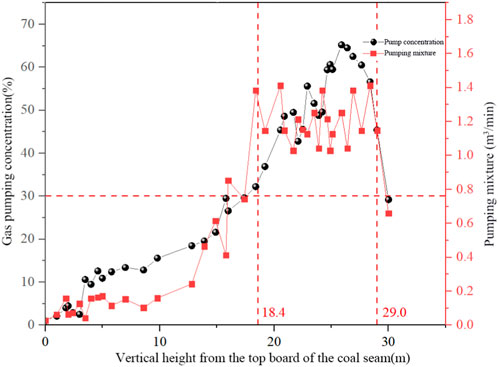
FIGURE 9. Change curves of gas concentration and extraction volume of 30-4# borehole.
Comparing Figures 7–9, it can be seen that the extraction changes of the three boreholes are basically the same. From the time when the working face advances to the end hole of the borehole until it exceeds the opening of the borehole, the gas extraction volume of each borehole increases from small to large, then decreases, conforming to a parabolic distribution. When the working face pushes a short distance past the end hole of the borehole, the extraction volume and gas concentration of the borehole significantly increase, and a high extraction volume and extraction concentration are maintained, indicating that the bottom of the borehole begins to enter the fracture zone. However, when the working face pushes past a certain distance of the borehole, the gas concentration of the borehole significantly reduces, indicating that the borehole starts to enter the caving zone. And as the borehole enters the goaf caving zone, the collapse of the overburden causes the borehole to be blocked, and the extraction volume of the borehole also significantly decreases.
As can be seen from Figure 7, with the working face advancing to the end hole of the 35-2# borehole, the vertical height of the end hole of the borehole from the coal seam roof gradually decreases. The gas concentration and extraction volume of the borehole overall gradually increase and then gradually decrease. When the end hole of the borehole is 20.0–30.0 m vertically above the coal seam roof, the gas concentration of the borehole is generally high (38.5%65.5%). When the vertical height of the end hole of the borehole from the coal seam roof is 25.928.4 m, the gas concentration is in the peak area (average 63.3%). With the gradual advancement of the working face, the borehole gradually enters the roof caving zone, causing the extraction volume to gradually decrease. Throughout the service period of the borehole, the gas extraction change curve of the borehole is generally parabolic.
As can be seen from Figure 8, the gas extraction change curve of the 35-8# high-level borehole is still generally parabolic throughout its service period. When the vertical height of the end hole of the borehole from the coal seam roof is 18.6–29.2 m, the overall gas concentration of the borehole is relatively high (34.9%–63.2%). When the vertical height of the end hole of the borehole from the coal seam roof is 25.9–27.7 m, the gas concentration is in the peak area, with an average value of 62.1%.
As shown in Figure 9, during the service period of the 30-4# high-level borehole, when the vertical height of the end hole of the borehole from the coal seam roof is 18.4–29.0 m, the overall gas concentration of the borehole is relatively high (36.9%–65.2%). When the vertical height of the end hole of the borehole from the coal seam roof is 24.6–27.6 m, the gas concentration is in the peak area, with an average value of 61.7%.
During the inspection period, the gas extraction, return wind concentration, and upper corner concentration of the 25030 working face are shown in Figure 10.
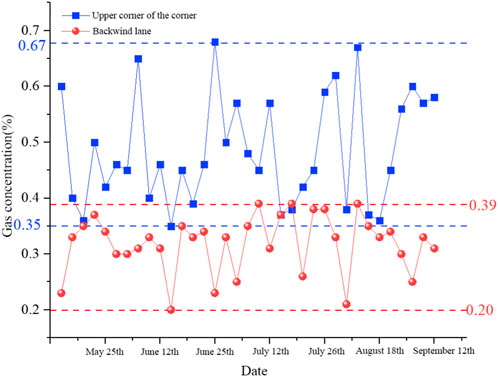
FIGURE 10. Changes in the gas concentration in the upper corner and return wind lane of the 25030 working face.
As shown in Figure 10, due to the extraction of the high-level boreholes, the upper corner concentration is controlled between 0.35%–0.67%, with an average of 0.51%, and the return wind lane concentration is controlled between 0.20%–0.39%, with an average of 0.30%. Therefore, the issue of gas exceeding the limit in the upper corner and the working face is basically eliminated, ensuring the safe production of the 25030 working face.
(1) The preliminary calculation of the “vertical three zones” height of the goaf overburden was conducted using empirical formulas, obtaining that the maximum vertical height of the caving zone from the coal seam roof is within the range of 5.5–9.2 m, and the maximum vertical height of the water-conducting fracture zone from the coal seam roof is within the range of 26.0–37.2 m.
(2) The preliminary calculation of the “vertical three zones” height of the goaf overburden was conducted using empirical formulas, obtaining that the maximum vertical height of the caving zone from the coal seam roof is within the range of 5.5–9.2 m, and the maximum vertical height of the water-conducting fracture zone from the coal seam roof is within the range of 26.0–37.2 m.
(3) The field investigation and analysis were conducted using the borehole gas extraction effect method. High-level boreholes were arranged for detection, and the results showed that as the vertical height of the end hole of the borehole from the coal seam roof gradually decreases, the gas concentration and extraction volume of the borehole overall gradually increase and then decrease, and the change curve of the borehole gas extraction is generally parabolic. When the vertical height of the end hole of the borehole from the coal seam roof is 18.4–30.0 m, the overall gas concentration of the borehole is relatively high. When the vertical height of the end hole of the borehole from the coal seam roof is 24.6–28.4 m, the gas concentration is in the peak area.
(4) The distribution ranges of the “vertical three zones” of the overlying strata in the 2-25030 working face of Xuehu Mine obtained by the three methods are roughly close. It is suggested to refer to the measured values in the design of gas extraction in the goaf. The test results show that the gas extraction effect is best when the vertical distance from the coal seam roof is 24.6–28.4 m. It is suggested that the mine arrange high-level boreholes in this area.
The original contributions presented in the study are included in the article/Supplementary Material, further inquiries can be directed to the corresponding author.
CL: Data curation, Formal Analysis, Investigation, Writing–original draft, Writing–review and editing. XZ: Conceptualization, Data curation, Resources, Supervision, Writing–review and editing. LH: Methodology, Validation, Writing–review and editing.
The authors declare financial support was received for the research, authorship, and/or publication of this article. National Natural Science Foundation of China (51734007, 51704099, and 52074106).
The authors declare that the research was conducted in the absence of any commercial or financial relationships that could be construed as a potential conflict of interest.
All claims expressed in this article are solely those of the authors and do not necessarily represent those of their affiliated organizations, or those of the publisher, the editors and the reviewers. Any product that may be evaluated in this article, or claim that may be made by its manufacturer, is not guaranteed or endorsed by the publisher.
Chen, S. J., Du, Z. W., Zhang, Z., Zhang, H., Xia, Z., and Feng, F. (2020). Effects of chloride on the early mechanical properties and microstructure of gangue-cemented paste backfill. Constr. Build. Mater. 235 (2), 117504. doi:10.1016/j.conbuildmat.2019.117504
Chen, S. J., Zhao, Z. H., Feng, F., and Zhang, M. Z. (2022). Stress evolution of deep surrounding rock under characteristics of bi-modulus and strength drop. J. Central South Univ. 29 (2), 680–692. doi:10.1007/s11771-022-4945-5
Gao, J., and Chen, S. (2016). Numerical simulation of "three zones" division of overlying rock strata in goaf. J. Saf. Environ. 16 (1), 36–39.
Li, C., Zhang, Y., Jia, L., and Zhang, G. (2017). High-level drilling extraction Technology of macro gas flow channel in goaf. J. Min. Saf. Eng. 34 (2), 391–397.
Li, H. T., Li, X. L., Fu, J. H., Gao, Z., Chen, P., and Zhang, Z. (2023a). Research on acoustic emission multi-parameter characteristics in the failure process of imitation steel fiber reinforced concrete. Phys. Fluids 35 (6), 107109. doi:10.1063/5.0170179
Li, H. T., Li, X. L., Fu, J. H., Zhu, N., Chen, D., Wang, Y., et al. (2023b). Experimental study on compressive behavior and failure characteristics of imitation steel fiber concrete under uniaxial load. Constr. Build. Mater. 399 (8), 132599. doi:10.1016/j.conbuildmat.2023.132599
Li, S., Xu, P., Zhao, P., and Lin, H. (2018). Time-induced effect of mining fracture elliptical throwing zone and gas extraction Technology. Coal Sci. Technol. 46 (9), 146–152.
Liu, S. M., and Li, X. L. (2023). Experimental study on the effect of cold soaking with liquid nitrogen on the coal chemical and microstructural characteristics. Environ. Sci. Pollut. Res. 30 (3), 36080–36097. doi:10.1007/s11356-022-24821-9
Lv, X., Li, R., and Cao, W. (2019). Research on the rationality of high-level drilling terminal layer position in large mining height face of thick coal seam. Coal Technol. 38 (1), 39–41.
Ma, Q., Liu, X. L., Tan, Y. L., Elsworth, D., Shang, J., Song, D., et al. (2023). Numerical study of mechanical properties and microcrack evolution of double-layer composite rock specimens with fissures under uniaxial compression. Eng. Fract. Mech. 289 (2), 109403. doi:10.1016/j.engfracmech.2023.109403
Pan, R., Hu, D., Jiangkun, C., Han, X., Jia, H., and Cong, L. (2023a). Oxidation and exothermic properties of long flame coal spontaneous combustion under solid-liquid-gas coexistence and its microscopic mechanism analysis. Sci. total Environ. 895, 165206. doi:10.1016/j.scitotenv.2023.165206
Pan, R., Zhang, T., Jiangkun, C., Hu, D., Liu, W., and Wang, L. (2023b). Study on thermal effects and gases derivation of spontaneous combustion of gas-containing coal. Fuel 354, 129336. doi:10.1016/j.fuel.2023.129336
Sun, R., Li, Q., Fang, J., and Xu, C. (2017). Construction Technology and development trend of high-level drilling in goaf gas extraction. Coal Sci. Technol. 45 (1), 94–99+213.
Wang, H., Wang, F., Gao, Y., Yan, J., Li, J., Cao, H., et al. (2019b). Optimization design of high-level drilling parameters based on luning coal mine. China Min. 28 (10), 131–137.
Wang, S., Zhao, J., and Zhang, L. (2019a). Numerical simulation study on the development of mining fractures in roof of shen'nan coal mine. Coal Mine Saf. 50 (10), 231–234.
Ye, D., Liu, G., Ma, T., Cheng, G., Fan, S., and Yang, T. (2023b). The mechanics of frost heave with stratigraphic microstructure evolution. Eng. Geol. 319, 107119. doi:10.1016/j.enggeo.2023.107119
Ye, D. Y., Liu, G. N., Wang, F. T., Gao, F., Yang, T. T., and Zhu, J. Y. (2023a). Fractal hydrological-thermal-mechanical analysis of unconventional reservoir: a fracture-matrix structure model for gas extraction. Int. J. Heat Mass Transf. 202, 123670. doi:10.1016/j.ijheatmasstransfer.2022.123670
Yuan, L. (2016). Reflections on the strategy of coal and gas Co-mining in deep areas of China. J. Coal Sci. 41 (1), 1–6.
Keywords: gas enrichment area, high level borehole, fracture zone, movement of overburden strata, gas drainage effect
Citation: Lu C, Zhang X and Han L (2023) Study on movement law of overburden strata and fracture zone height in deep mining work face. Front. Earth Sci. 11:1308369. doi: 10.3389/feart.2023.1308369
Received: 06 October 2023; Accepted: 20 October 2023;
Published: 28 December 2023.
Edited by:
Yubing Liu, China University of Mining and Technology, ChinaReviewed by:
Xuelong Li, Shandong University of Science and Technology, ChinaCopyright © 2023 Lu, Zhang and Han. This is an open-access article distributed under the terms of the Creative Commons Attribution License (CC BY). The use, distribution or reproduction in other forums is permitted, provided the original author(s) and the copyright owner(s) are credited and that the original publication in this journal is cited, in accordance with accepted academic practice. No use, distribution or reproduction is permitted which does not comply with these terms.
*Correspondence: Linxiu Han, ZG91Ymxld29vZHhpdUAxNjMuY29t
Disclaimer: All claims expressed in this article are solely those of the authors and do not necessarily represent those of their affiliated organizations, or those of the publisher, the editors and the reviewers. Any product that may be evaluated in this article or claim that may be made by its manufacturer is not guaranteed or endorsed by the publisher.
Research integrity at Frontiers
Learn more about the work of our research integrity team to safeguard the quality of each article we publish.