 Changgeng Hu
95% of researchers rate our articles as excellent or good
Learn more about the work of our research integrity team to safeguard the quality of each article we publish.
Find out more
ORIGINAL RESEARCH article
Front. Earth Sci. , 28 December 2023
Sec. Geoinformatics
Volume 11 - 2023 | https://doi.org/10.3389/feart.2023.1298414
This article is part of the Research Topic Response and Catastrophe Mechanisms of Geotechnical Underground Exploration: Theories and Numerical Modeling View all 14 articles
The construction of expressway tunnels in karst areas faces many challenges under complex geological conditions. It is of great scientific and engineering significance to study the deformation and failure laws of tunnels and surfaces. Taking the Qilinguan tunnel of the Hubei Expressway as an example, the deformation and failure laws of the tunnel are analyzed when the tunnel passes through the complex karst area. The composition of karst water and surrounding rock was analyzed by inductively coupled plasma mass spectrometry and XRD, and the compression-shear failure model of tunnels in karst areas was proposed according to the regional hydrological and geological conditions. It was found that the thickness of the protective layer and the water pressure were the main factors affecting the deformation and failure of the surrounding rock in this area, and the treatment scheme of this project was put forward accordingly. The geological characteristics of karst areas were explored by advanced geological prediction and advanced geological drilling. The primary support is provided by a steel arch and advanced small pipe grouting. The composite lining is composed of shotcrete as the primary support and molded concrete as the secondary lining. The primary support structure of the flexible support system is adopted in the design to give full play to the bearing capacity of the surrounding rock. After the support measures were adopted, the trend of settlement change gradually slowed down, indicating that the support measures were effective.
More than half of China’s completed tunnels are located in karst areas (Hui et al., 2018; Xu et al., 2021). The karst area poses a huge geologic hazard to highway tunnel construction and remains a potential risk for normal operations (Tian et al., 2018; Li et al., 2019). In the mountainous areas of Southwest China, the engineering, geological, and hydrogeological conditions are complex, and the karst development is changeable (Li and Li, 2014; Li and Wu, 2019). It is difficult to deal with the geological disasters in karst areas in all aspects during construction. Under the condition of a rainstorm, the surrounding rock fissure water is abundant, which forms great pressure on the tunnel face and lining, and the tunnel lining is prone to deformation and failure (Alija et al., 2013; Liu et al., 2019; Huang et al., 2022). Therefore, it is of great significance to study the deformation and failure laws of tunnel lining and surface in karst areas under complex geological conditions.
In order to study the deformation and failure characteristics of tunnels in karst areas, a series of effective studies have been carried out at home and abroad (Chen et al., 2020; Gang-jian et al., 2022; Liu et al., 2022). The representative studies are discussed in this paragraph. Jin (2020) studied the disaster-causing conditions of local high-water-depth buried tunnels and proposed that the disaster-causing conditions of deep, local pressure-bearing tunnels are mainly the vertical development of karst. Fan et al. (2022) carried out the mechanical response model test of a water-rich pipeline karst tunnel and studied the internal force characteristics of the lining structure under the influence of different cavity positions and different water head heights. It is found that when there is a pipeline-type cavity around the tunnel, the inner side of the lining in contact with the cavity bears a large positive bending moment, which is the most unfavorable stress position of the lining structure. Jia-qi et al. (2018) used the critical water pressure formula to establish a criterion for the instability and water inrush of the intermittent joint outburst prevention layer of the karst tunnel face based on the minimum safe thickness and then analyzed the karst water pressure in front of the tunnel face. At the same time, the study examined the effects of the intermittent main cracks, the spacing of intermittent cracks, and the angle between cracks and the maximum principal stress on the thickness of the minimum safety outburst prevention layer. In summary, a series of studies have been carried out on the deformation and failure characteristics of tunnels in karst areas. However, in the current research, the composition of surrounding rock and karst water is rarely analyzed, and the in-depth analysis of its deformation and failure mechanisms is lacking (Luo et al., 2022). Therefore, for karst areas with complex geological conditions, the development process of lining and surface deformation and failure in tunnels need further study.
In this paper, the Qilinguan extra-long tunnel of the Hubei Expressway was taken as an example, the characteristics of lining and surface deformation and failure in the cave are expounded. By analyzing the composition of the weak interlayer in the surrounding rock, the compression-shear failure model of the tunnel in this area was put forward. It was found that the thickness of the surrounding rock protection layer and fissure water pressure are the main factors affecting the deformation and failure of the surrounding rock in this area, and the treatment scheme was put forward accordingly. Based on advanced geological prediction and drilling, the construction treatment scheme in karst areas is put forward. The deformation monitoring of the surface and the hole shows that the treatment has achieved good results. The research results can provide theoretical and engineering support for the study of the deformation and failure of expressway tunnels in karst areas.
The Yidu end of the Qilinguan extra-long tunnel is located in Dagou Village, Wangjiafan Township, Yidu City, Hubei Province, and the Hunan end is located in Qilinguan Village, Yuyangguan Town, Wufeng Tujia Autonomous County, Hubei Province. It is a four-lane highway tunnel with up-and-down separation. The starting and ending stake number of the left line is ZK7 + 914∼ZK16 + 129, with a length of 8,215 m. The pile number of the right hole is YK7 + 931∼YK16 + 156, and the length is 8,225 m. The Yidu end of the left and right lines is located on the straight line. The Hunan end is on the left circular curve with R = 4,950 and R = 5,600, respectively. The spacing between the left and right lines of the Yidu end of the tunnel is 29.1 m, the maximum spacing of the tunnel body is approximately 40.0 m, and the spacing of the Hunan end is gradually changed to 25.1 m.
The tunnel area belongs to the low mountain landform and platform terrain of structural denudation and erosion. The tunnel crosses the east–west mountains of Renheping and is located on the north bank of the Nanhe River. The ground elevation of the crossing area is generally approximately 420 m–930 m, and the surface topography of the mountain top is undulating. The entrance of the tunnel is a sudden mountain mouth where two ditches meet. The slope is steep, and there is still high-level land above. The Yidu section is sandy shale, and the rock mass joints are developed. The slope block is loose, and the top is a kaolin mining area. The slope angle is 40°, and the inclination is approximately 30°. The south river at the Hunan end of the tunnel is a deep valley formed by deep karst dissolution. The bank slopes on both sides are steep. The portal is a concave bank slope, with a slope angle of 45° and a tendency of 180°. The surface and groundwater above the tunnel are developed, and the groundwater in the tunnel area is mainly karst water. Groundwater recharge mainly occurs through atmospheric rainfall. Discharge methods mainly include groundwater discharge, surface runoff, and evaporation.
When the right working face of the tunnel was constructed to YK15 + 667, the cavity collapsed, and the excavation of the working face was suspended. The design elevation of the tunnel working face here is 531.8 m, the surface elevation is approximately 625.3 m, and the buried depth is approximately 93 m. At this time, the working face of the left hole was constructed to ZK15 + 479, and the secondary lining was constructed to ZK15 + 588. Due to the large-scale karst cavity, the tunnel lining is deformed and damaged, the water seepage in the tunnel is serious, and the ground fissures appear on the surface.
The Qilinguan tunnel was excavated from the large pile number to the small pile number. On 6 March 2022, when the right hole was excavated to YK15 + 690, cracks appeared on the upper right side of the tunnel face, and water flowed out. During the construction, the drainage pipe was pre-buried at this fissure. From the time of burial to the present day, there has been an outflow of water. There was no mud at the outlet, and the water flow was clear.
On 12 March 2022, when the working face of the right tunnel reached YK15 + 667, a cavity collapse occurred on the upper left side of the working face. The collapse was yellow mud with stones. After the collapse, the initial support steel frame was intact, and there was no crack on the surface of the initial support shotcrete. There has been soil and rock falling in the collapse cavity, which cannot be observed, and the situation in the cavity is unknown. According to the monitoring results, the initial settlement and convergence of the right hole still exceed the warning value after the anti-pressure measures are taken in the tunnel working face. The surface of the collapse section is a sinkhole, where the buried depth is approximately 93 m. After the collapse occurs, the working face of the roadway immediately backfills approximately 500 cubic meters of waste rock, and the top of the back pressure area is approximately 7 m from the excavation working face. The photographs of the site under study are shown in Figure 1.
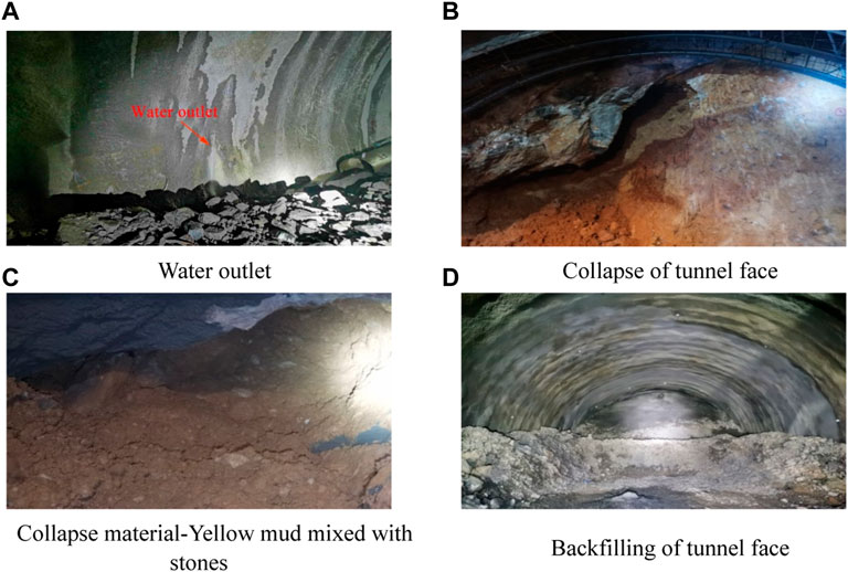
FIGURE 1. Deformation and failure characteristics of the tunnel. (A) Water outlet. (B) Collapse of the tunnel face. (C) Collapse material: yellow mud mixed with stones. (D) Backfilling of the tunnel face.
The analysis shows that there are two main reasons for the collapse. First, there are deposits with a large area, large range, and high height on the left side of the entry direction, which can easily lead to stress concentration and local instability. Second, the recent rainy weather is concentrated, and the rainwater enters the accumulation body through the cavity, which increases the water content of the cave top and the accumulation body. Due to these reasons, the self-stability of the accumulation body becomes worse and the sliding pressure is generated, which leads to the instability and deformation of the left arch of the vault under earth pressure.
The surface of the cave top is situated in a mountainous area with higher terrain surrounding it and lower terrain in the middle, and no one lives within 600 m. It is a deep sinkhole. After the face of the tunnel collapsed, the top of the cave was immediately examined. It was found that there were irregular annular cracks on the surface of the top of the cave, with an area of approximately 750 m2. The photographs of the surface cracks are shown in Figure 2. The surface cracks are mainly distributed between the left and right sides of the tunnel and the top of the right side of the tunnel, with an irregular ring. After cracking, the widest crack width was observed for the first time in the middle of the left and right amplitudes, with a width of approximately 20 cm.
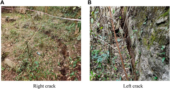
FIGURE 2. Surface cracks. (A) Right crack. (B) Left crack.
The supporting structure of the tunnel adopts the composite lining by applying the principle of the new Austrian method. The construction unit must carry out on-site monitoring during the construction process and timely grasp the mechanical characteristics of the surrounding rock and supporting structure during the excavation process. Based on this, the stability of the surrounding rock and supporting structure is evaluated to provide comprehensive information for tunnel construction so as to adjust the supporting parameters in time. Through data analysis, the stable state of surrounding rock support is predicted, and corresponding construction measures are formulated. According to the actual situation of the site, the monitoring is divided into two categories: the hole and the ground. Each type of monitoring project includes the required and selected test items. The specific monitoring scheme is shown in Figure 3. In order to distinguish, Figure 3A describes the surface deformation area, and Figure 3B describes the distribution of surface monitoring points.
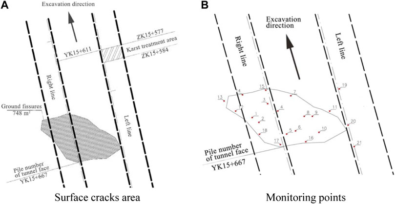
FIGURE 3. Surface crack area and monitoring points. (A) Surface crack area. (B) Monitoring points.
The main object of ground monitoring and measurement is the surface condition, and there are two necessary items: (1) Surface observation: daily observation of surface geology and hydrology and observation of surface anomalies are noted. (2) Surface subsidence: according to the surface subsidence, the influence of excavation on the surface is judged, and the tunnel support structure is determined.
After the blasting of the YK15 + 667 right hole working face of the Qilinguan tunnel, the surface settlement at the top of the hole increased. The deformation law of settlement observation is shown in Figure 4. The monitoring results show that after the collapse of the karst area, the surface-affected area generally has obvious settlement, the maximum settlement value reaches 343 mm, and the settlement value of other areas is generally between 150 and 300 mm. After the roadway is supported, the settlement trend gradually slows down, indicating that the support measures are effective.
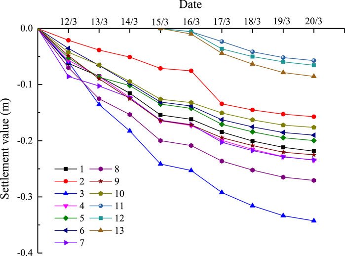
FIGURE 4. Surface subsidence tendency.
According to the tunnel engineering and hydrogeological characteristics, the cracks in this area are very developed, and the groundwater is sufficient. In order to study the failure mechanism of tunnel lining in this area, the weak interlayer of surrounding rock was sampled and analyzed by XRD. The results are shown in Figure 5. The analysis results show that the weak interlayer in this area contains a large number of clay minerals, carbonates, and sulfates, which are prone to seepage failure under high water heads. Based on this, it is considered that the failure mode of the lining and surrounding rock in this area is of hydraulic fracturing type. Under the high head pressure, the fissure water expands in the gap and induces a new fracture network. The fracture network gradually develops and finally induces the instability and failure of the lining and surrounding rock.
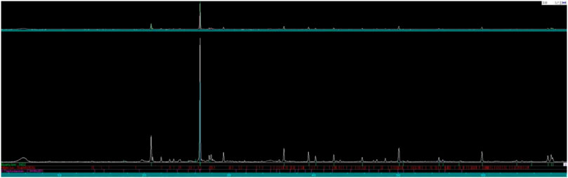
FIGURE 5. XRD analysis results of the weak interlayer.
In order to study the mechanical properties of the surrounding rock, samples were collected from typical areas, and uniaxial compression tests were carried out. The test results are shown in Table 1. According to the experimental results, it can be found that the surrounding rock in the karst area is mainly muddy siltstone. The compressive strength of the surrounding rock is concentrated at 10–20 MPa, and the internal friction angle ranges from 29° to 32°. The composition of the surrounding rock shows that its strength and stability are significantly affected by karst water and mineral content. Therefore, it is necessary to analyze the composition of karst water.
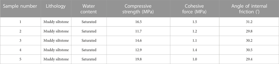
TABLE 1. Rock mass parameters.
The composition and chemical properties of karst water have an important influence on the stability of the lining structure and surrounding rock. The karst water is analyzed by inductively coupled plasma mass spectrometry and other methods. The results are shown in Table 2. The results show that the chemical composition of karst water in this area is low, and the corrosion is weak. Therefore, when analyzing the stability of the surrounding rock in the karst area, we do not need to consider the chemical weakening effect of karst water on the surrounding rock; however, we mainly need to analyze the deformation and failure mechanisms of the surrounding rock from a mechanical point of view.
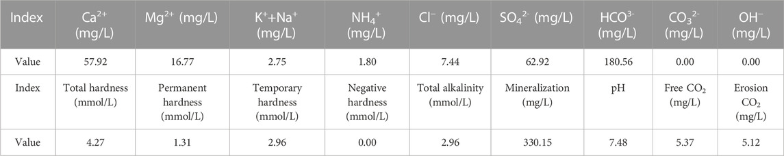
TABLE 2. Chemical composition of karst water.
Based on this, a compression-shear model of surrounding rock deformation and failure is established, as shown in Figure 6.
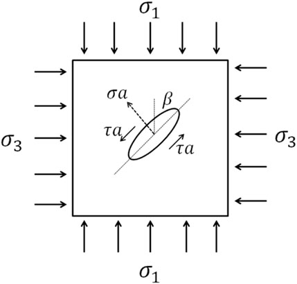
FIGURE 6. Compression-shear calculation model.
From this model, the normal stress and shear stress on the unit body can be known, as shown in Formula 1.
For this model, the distribution of the fracture discontinuous stress field is given as follows:
Here, K1 is the stress intensity parameter at the crack tip, and its expression is as follows:
The fracture will be closed under pressure, and the closed fracture can withstand pressure and shear stress. Based on the theory of fracture mechanics, the critical head pressure at which hydraulic fracturing occurs can be deduced, as shown in Eq. 4.
The tunnel lining is subjected to external water and mountain loads, and the lining thickness should be able to withstand its pressure without damage. In order to select a reasonable support type and carry out support design, it is necessary to analyze the lining thickness. Assuming that the lateral load is a trapezoidal distribution, the maximum bending moment of the lining is calculated as follows:
where p and p’ are water pressure at the tunnel roof and floor and H is the height of the tunnel.
At the same time, the maximum shear force of the lining is
The minimum thickness of the lining is calculated using bending strength and shear strength, respectively, as follows:
where ρ is the density of karst water, g is the acceleration of gravity, σt is the tensile strength of the lining, and τ is the shear strength of the lining.
In karst areas, there are often broken stones and other objects in the outer cavity of the tunnel lining. Considering this factor, the aforementioned critical lining thickness is corrected to the following expression:
where λ is the lateral pressure coefficient and γ is the bulk density of fillings in the karst cavity.
It can be found that the thickness of the protective layer of the surrounding rock and the fissure water pressure are the main factors affecting the deformation and failure of the surrounding rock in this area. Based on this, the treatment measures in the karst area of the tunnel can be put forward.
The YK15 + 850∼YK15 + 560 right hole of the Qilinguan tunnel is explored as moderately weathered, thick-layered limestone. Although the strength of the rock mass is high, there are deep collapse holes on the top surface of the section, and the holes contain continuous karst caves. There may be a large number of karst caves with silty clay fillings above the design elevation. At the same time, due to the action of compression-torsion faults, the rock mass is relatively broken, and it is possible to cut into the karst water channel. Instantaneous water inrush and mud gushing may occur during excavation and rainy season construction, and the water inflow is large. The groundwater system is mainly connected with karst water, surfaces, and large karst caves. Local cracks or karst development sites are prone to extensive, sudden outflows of water and mud gushing during construction excavation and the rainy season. Therefore, it is necessary to predict the support in advance, take waterproof measures, and adopt effective measures to control karst water and karst caves. There are a large number of silty clay and limestone fragments at the top of the tunnel, so it is necessary to prevent them from falling or collapsing. The construction period of the tunnel is short, the blasting is weak, and the support needs to be strengthened during treatment.
According to the advanced geological prediction results of the YK15 + 667∼YK15 + 637 section of the Qilinguan Tunnel Project of the HBSG-2 Bid of the Hubei Expressway, the mileage of the tunnel face is YK15 + 667 in this prediction, and the predicted mileage range is YK15 + 667∼YK15 + 637 (i.e., 30 m in front of the tunnel face). The detection results are shown in Figure 7.
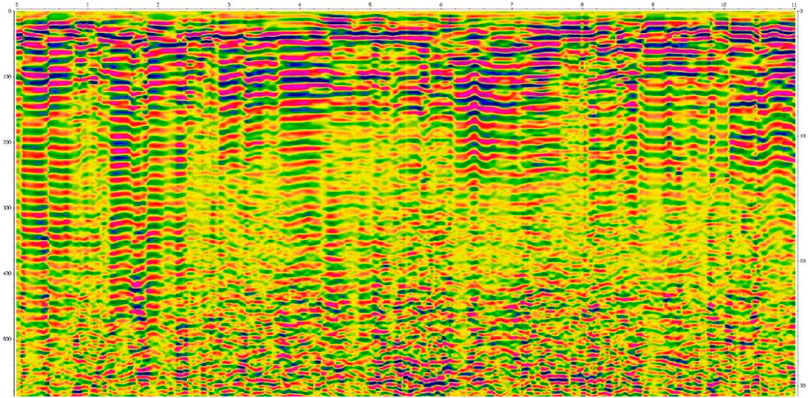
FIGURE 7. Detection results of geology radar.
The advanced prediction range is 30 m in front of the working face of the roadway. The exposed surrounding rock state of the tunnel working face is moderately weathered argillaceous siltstone and limestone. A mud cave cavity is exposed on the left side, with moderate water seepage and a lot of mud. The tunnel rock mass is broken, the stability of the surrounding rock is general, and the integrity is poor. From the radar detection results, it can be seen that the radar signal response of the YK15 + 667∼YK15 + 653 section in front of the working face of the roadway is obvious, and the radar wave phase is discontinuous in many places. According to this, it is speculated that the surrounding rock of this section is relatively broken, the interlayer bonding of rock mass is poor, and the surrounding rock in the middle of the roadway working face is slightly worse than that on both sides. In the YK15 + 659 mileage section, the radar reflection signal is abnormal, and the in-phase axis is discontinuous. It is speculated that this is the overlapping surface of the rock mass medium, and the joints and fissures of the interlayer rock mass are developed. Unfavorable geological phenomena such as seepage and formation of mud or small cavities are the common challenges that may be encountered during tunnel construction. In the range of YK15 + 653∼YK15 + 637, the radar signal reflection signal is weak, the energy group is unevenly distributed, and there is no obvious bad reflection wave. It is speculated that the overall situation of the surrounding rock in this section is roughly consistent with the current tunnel face. Through the observation and analysis of the surrounding rock of the tunnel face, the grade of the tunnel face is V grade.
In order to find out the geological conditions in front of the tunnel face, advanced drilling was carried out on the tunnel face, and a 150-m-long drilling rig was used for advanced drilling. The mileage pile number of the drilling hole is YK15 + 674, and the backfill slag accumulation section is 7 m away from the tunnel face. The details are shown in Figure 8.
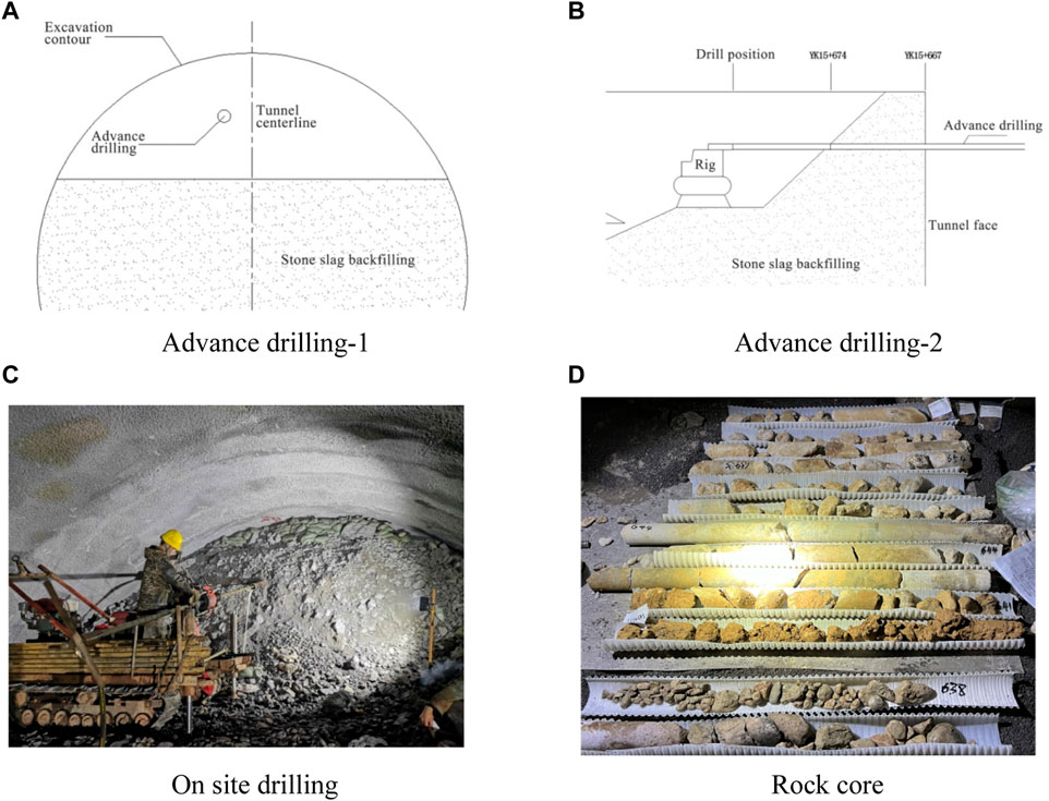
FIGURE 8. Advance drilling and rock core. (A) Advance drilling-1. (B) Advance drilling-2. (C) On-site drilling. (D) Rock core.
In this advanced drilling, the mileage of the working face is YK15 + 667, and the drilling mileage range is YK15 + 667∼YK15 + 629 (38 m in front of the working face). The preliminary analysis results are shown in Table 3.
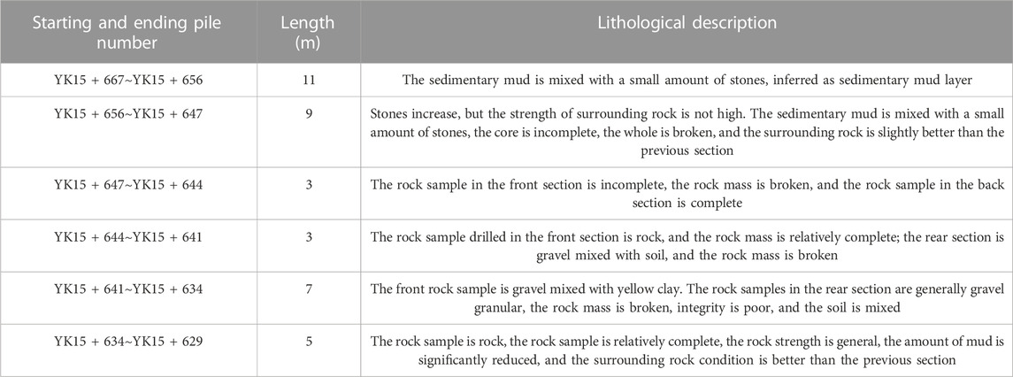
TABLE 3. Drilling results.
(1) The 108 × 6 mm hot-rolled seamless steel pipe with 40 cm circumferential spacing is used for advanced support, and the supporting length of the advanced steel pipe should not be less than 10 m per cycle. It can be divided into multiple cycles, and the construction site determines the advance support length according to the advance geological forecast. In order to ensure that there is still enough advance support length at the distal end of the steel pipe after excavation, the longitudinal lap length of the steel pipe is not less than 3 m, and the extension into the stable stratum is not less than 3 m. When the surrounding rock is broken and it is difficult to form a hole, the pipe drilling process can be used.
(2) I20 b is adopted for the initial support steel frame, the longitudinal spacing is 50 cm, and the connection between the steel frames is welded at 100 × 80 × 10. The temporary support pad at the locking foot of the arch section adopts I20 steel or 25 mm steel plate, and the adjacent arches are welded together by steel or steel plate. The bottom of the arch foot is a weak layer. Two φ108 × 6 mm steel pipes are added to the arch foot of the steel frame and welded firmly with the steel frame as the support of the steel frame using φ10 steel mesh (10 × 10 cm) and a 40-cm-thick C25 shotcrete.
(3) According to the monitoring data of the tunnel, the temporary stable state of the surrounding rock can be used to deal with the slag while cleaning the slag. The excavation section can be appropriately increased, and the spray anchor support can be used to reinforce the uncollapsed strata as soon as possible. After being relatively stable and safe, the grid arch + sprayed C25 concrete is used to strengthen the support along the outer contour of the inner primary support, and the support is divided into multiple layers. After the settlement deformation data of the inner and outer initial support monitoring and measurement are stable, the secondary lining is applied.
(4) The filling section of cohesive soil at the bottom of the inverted arch adopts φ108 × 6 mm grouting steel pipe, with L = 8 m. The longitudinal circumferential spacing is 50 (longitudinal) × 100 (ring), and the plum-shaped arrangement is reinforced.
(5) The secondary lining adopts 60-cm-thick C35 waterproof reinforced concrete (waterproof grade is not less than P10).
(6) According to advanced geological prediction and monitoring measurement, the excavation of the tunnel body is carried out using ring excavation with reserved core soil, central diaphragm (CD), and cross-central diaphragm (CDR) methods, and the long bench method is not suitable. According to the monitoring measurement, the support parameters and construction methods can be optimized and adjusted. In construction, site safety management should be strengthened to ensure construction safety.
The right hole of the Qilinguan tunnel is located in the complex area of engineering geology and hydrogeology. When it was constructed to YK15 + 667, a large-scale cavity collapse occurred. Through field monitoring, mechanical experiments, chemical analysis, and theoretical research, the deformation and failure mechanisms of the karst failure area are obtained, and treatment measures are put forward. The main conclusions are as follows:
(1) After the deformation and failure of the tunnel in the karst area, the collapse form is yellow mud with stones, and there are cracks on the upper right of the tunnel working face, accompanied by moderate seepage. A soil fall has occurred in the cave, and the situation in the cave is unknown. After the back pressure measures are taken in the roadway working face, the initial settlement and convergence of the right hole are within the warning range. There are irregular annular cracks on the top surface of the cave, and the crack area is approximately 750 m2. The surface cracks are mainly distributed between the left and right sides of the roadway and the top of the right side of the roadway, showing an irregular ring. The maximum settlement value is 343 mm, and the settlement value in other areas is generally between 150 and 300 mm.
(2) The composition of the weak interlayer of the surrounding rock was analyzed by XRD, the mechanical properties of the surrounding rock were measured using uniaxial compression tests, and the karst water was analyzed by inductively coupled plasma mass spectrometry. According to the analysis results, the compression-shear failure model of the tunnel in the karst area was proposed. It was found that the surrounding rock in the karst area is mainly muddy siltstone, the chemical composition of the karst water in this area is low, and the corrosion is weak. The thickness of the protective layer of the surrounding rock and the pressure of fissure water were the main factors affecting the deformation and failure of the surrounding rock in this area.
(3) Through advanced geological prediction and advanced geological drilling, the development of the karst area in front of the tunnel face is proved. The ring excavation reserved core soil method, middle partition method (CD method), and cross-middle partition method (CDR method) are selected for construction. The support parameters and construction methods are optimized and adjusted according to monitoring and measurement. In the design, the initial support structure of the flexible support system is adopted to give full play to the bearing capacity of the surrounding rock. Through on-site monitoring, it was found that the disposal method had a good effect.
The raw data supporting the conclusion of this article will be made available by the authors, without undue reservation.
CH: writing–original draft and writing–review and editing.
The author(s) declare that financial support was received for the research, authorship, and/or publication of this article.
The data used in this paper are available upon request from the corresponding author.
Author HC was employed by the company CCCC-SHEC First Highway Engineering Co., Ltd.
The authors declare that this study received funding from the Specialized Research Fund of China Communications Construction Co., Ltd. (20220513). The funder had the following involvement in the study: study design and data collection.
All claims expressed in this article are solely those of the authors and do not necessarily represent those of their affiliated organizations, or those of the publisher, the editors, and the reviewers. Any product that may be evaluated in this article, or claim that may be made by its manufacturer, is not guaranteed or endorsed by the publisher.
Alija, S., Torrijo, F. J., and Quinta-Ferreira, M. (2013). Geological engineering problems associated with tunnel construction in karst rock masses: the case of Gavarres tunnel (Spain). Eng. Geol. 157, 103–111. doi:10.1016/j.enggeo.2013.02.010
Chen, Y. F., Liao, Z., Zhou, J. Q., Hu, R., Yang, Z., Zhao, X. J., et al. (2020). Non-Darcian flow effect on discharge into a tunnel in karst aquifers. Int. J. Rock Mech. Min. Sci. 130, 104319. doi:10.1016/j.ijrmms.2020.104319
Fan, H.-B., Zhou, D.-k., Liu, Y., Song, Y.-X., Zhu, Z.-G., Zhu, Y.-q., et al. (2022). Mechanical response characteristics ofining structure of pipeline karst tunnels in water-rich areas. Rock Soil Mech. 43 (7), 1884–1898. doi:10.16285/j.rsm.2021.6730
Gang-jian, A., Zheng-zheng, C., Hong-fei, D., Guo-sheng, L., and Ao, L. (2022). Mechanical response of surrounding rock of karst tunnel under stress-damage-seepage coupling effect. Geofluids 2022, 1–11. doi:10.1155/2022/6879808
Huang, C., Dong, W., Cao, Z., Wang, Y., An, G., Chen, H., et al. (2022). Water inrush mechanism of fault zone in karst tunnel under fluid-solid coupling field considering effective stress. Geofluids, 2022. doi:10.1155/2022/4205174
Hui, H., Bowen, Z., Yanyan, Z., Chunmei, Z., Yize, W., and Zeng, G. (2018). The mechanism and numerical simulation analysis of water bursting in filling karst tunnel. Geotechnical Geol. Eng. 36 (2), 1197–1205. doi:10.1007/s10706-017-0386-6
Jia-Qi, G., Yan-bin, L. U. O., Fan, C., Yan-Bin, L., Qin, L., et al. (2018). Water inrush criterion and catastrophe process of a karst tunnel face with non-persistent joints. China J. Highw. Transp. 31 (10), 118–129. https://zgglxb.chd.edu.cn/CN/Y2018/V31/I10/118
Jin, M. (2020). Research on mechanical behavior of lining structure of concealed karst tunnel under local water pressure [D]. Chongqing: Chongqing University.
Li, S., Gao, C., Zhou, Z., Li, L., Wang, M., Yuan, Y., et al. (2019). Analysis on the precursor information of water inrush in karst tunnels: a true triaxial model test study. Rock Mech. Rock Eng. 52, 373–384. doi:10.1007/s00603-018-1582-2
Li, S. C., and Wu, J. (2019). A multi-factor comprehensive risk assessment method of karst tunnels and its engineering application. Bull. Eng. Geol. Environ. 78, 1761–1776. doi:10.1007/s10064-017-1214-1
Li, X., and Li, Y. (2014). Research on risk assessment system for water inrush in the karst tunnel construction based on GIS: case study on the diversion tunnel groups of the Jinping II Hydropower Station. Tunn. Undergr. Space Technol. 40, 182–191. doi:10.1016/j.tust.2013.10.005
Liu, Q., Sun, S., Wang, H., Dong, J., and Hu, H.s. (2020), A calculation method for safety distance between the confined karst cave and the shield tunnel based on upper bound theorem. Geotechnical Geol. Eng. 38, 6587–6599. doi:10.1007/s10706-020-01456-6
Liu, Y., Feng, Y., Xu, M., Zhang, Y., Long, H., and Zhu, H. (2019). Effect of an incremental change in external water pressure on tunnel lining: a case study from the Tongxi karst tunnel. Nat. Hazards 98, 343–377. doi:10.1007/s11069-019-03692-3
Luo, M., Chen, J., Jakada, H., Guo, X., and Zhou, H. (2022). Identifying and predicting karst water inrush in a deep tunnel, South China. Eng. Geol. 305, 106716. doi:10.1016/j.enggeo.2022.106716
Tian, Q., Zhang, J., and Zhang, Y. (2018). Similar simulation experiment of expressway tunnel in karst area. Constr. Build. Mater. 176, 1–13. doi:10.1016/j.conbuildmat.2018.04.209
Keywords: karst area, deformation and failure characteristics, karst water, compression-shear failure model, surface subsidence
Citation: Hu C (2023) Deformation and failure characteristics of high-speed tunnels in complex karst areas: a case at the Qilinguan tunnel. Front. Earth Sci. 11:1298414. doi: 10.3389/feart.2023.1298414
Received: 21 September 2023; Accepted: 31 October 2023;
Published: 28 December 2023.
Edited by:
Yongqiang Zhou, Chinese Academy of Sciences (CAS), ChinaReviewed by:
Guangdong Yang, China Three Gorges University, ChinaCopyright © 2023 Hu. This is an open-access article distributed under the terms of the Creative Commons Attribution License (CC BY). The use, distribution or reproduction in other forums is permitted, provided the original author(s) and the copyright owner(s) are credited and that the original publication in this journal is cited, in accordance with accepted academic practice. No use, distribution or reproduction is permitted which does not comply with these terms.
*Correspondence: Changgeng Hu, Y29uY3JldGVhbmR3b29kQG91dGxvb2suY29t
Disclaimer: All claims expressed in this article are solely those of the authors and do not necessarily represent those of their affiliated organizations, or those of the publisher, the editors and the reviewers. Any product that may be evaluated in this article or claim that may be made by its manufacturer is not guaranteed or endorsed by the publisher.
Research integrity at Frontiers
Learn more about the work of our research integrity team to safeguard the quality of each article we publish.