 Tao Wang1,2
 Weiwei Ye
 Liyuan Liu
- 1School of Civil and Resources Engineering, University of Science and Technology Beijing, Beijing, China
- 2Beijing Key Laboratory of Urban Underground Space Engineering, University of Science and Technology Beijing, Beijing, China
The increase in freezing depth requires thicker, stronger, and colder freezing walls, and various complex factors in deep strata greatly increase the risk of freezing pipe fracture. To address the phenomenon of freezing pipe fracture, this paper designs freezing pipe and joint mechanical performance experiments based on acoustic emission (AE) technology, mainly testing the deformation of freezing steel pipes and composite joints at normal and low temperatures, changes in load bearing capacity, and corresponding AE characteristics of the process. Additionally, the associated AE characteristics throughout the process will be analyzed. The ultimate goal is to establish a discriminative pattern for identifying the critical fracture of freezing pipes based on the analysis of AE signal characteristics in conjunction with mechanical properties. The sensitivity of the AE system under low-temperature conditions and the reliability of the test were tested through pencil lead break experiments, and saltwater noise detection experiments were conducted to prevent noise interference from low-temperature saltwater flow and pipe wall friction in the identification of crucial signals for freezing pipe fracture. This study provides a basis for identifying the deformation mechanics and fracture warning of freezing pipes through dynamic analysis of AE monitoring information.
1 Introduction
In freeze sinking, a method used for drilling in deep alluvial deposits, occurrences of wellbore wall fracturing and freezing pipe failures are not uncommon. Over the past 30 years, due to changes in energy structures, some developed countries have rarely initiated construction of large-scale freeze wellbores, and the development of freeze drilling technology has essentially stagnated (Li et al., 2011). In China, during the freeze sinking projects in the 1980s, particularly in the Lianghuai region, a large number of pipe failures and well flooding accidents were observed. While the continuous improvement of construction methods and the emergence of new technological solutions have facilitated the expansion of many domestic underground projects (Han et al., 2023), including artificial ground freezing techniques, the phenomenon of freezing pipe fractures in freeze well freezing has been temporarily brought under effective control. However, due to the lag in freeze technology theory, coupled with the increase in freeze circle diameter and the widespread adoption of multi-circle freeze schemes, a significant resurgence of freezing pipe fracture accidents has emerged once again (Sheng, 2009; Chen, 2012).
The safety of freezing pipes is one of the crucial factors determining the success or failure of freeze sinking projects. Scholars have conducted relevant research on the fracture mechanism and improvement measures of frozen pipes from various aspects, including frozen wall deformation, quality of frozen boreholes and frozen pipes, and blasting vibrations. Yang et al. (2013) established a relationship model between frozen wall displacement and the occurrence rate of pipe fractures based on statistical data, and used the maximum displacement of the frozen wall to predict the risk of frozen pipe fracture. Zheng et al. (2015) conducted numerical simulations, while Yang et al. (2016) performed engineering experiments to analyze the effects of blasting vibrations on frozen pipes. Wu and Lin (1992) designed flexible joints for frozen pipes by altering the stiffness and elongation rate of the joint location. Zhou (1996) calculated the stress and deformation characteristics of frozen pipes in the frozen wall deformation zone and during multi-loop freezing through stress analysis. Jing et al. (2004) established a more accurate mechanical model by analyzing the factors affecting the stress on frozen pipes during operation and studying the deformation characteristics. They conducted theoretical calculations to determine the critical locations of frozen pipe fracture. Zhang (2008) conducted tensile and bending tests on frozen pipes under both normal and low-temperature conditions, considering the presence or absence of joints. The results indicated the necessity of using inner lining steel pipes at the joint locations, as they demonstrated improved tensile and bending capacities. However, industry scholars’ focus is primarily on freezing theory (Cui et al., 2011), frozen soil mechanics (Yang et al., 2009; Zhao et al., 2013), design methods (Wang et al., 2010; Deng et al., 2023), fracture mechanism (Li et al., 2023) and related aspects. There is relatively less emphasis on the safety monitoring and evaluation of freezing pipes.
The assessment of freezing pipe fractures in a freezing station relies on observing certain direct or indirect phenomena. These include the saltwater tank and the advancing face of the wellbore, which provide clues about the occurrence of freezing pipe fractures. After a freezing pipe fracture occurs, several indications can be observed. The bottom heave volume at the working face increases significantly, and there is a noticeable displacement of the wellbore. Additionally, the temperature of the incoming air decreases, and there may be the presence of saltwater seepage from the wellbore or well wall, characterized by a bitter and turbid taste. A decline in the saltwater level within the saltwater tank becomes apparent, and discrepancies in flow rate may occur in the saltwater circulation loop. Within the freezing trench, one can hear a distinct sound of flowing saltwater, often resembling a thumping noise. Furthermore, the rubber hose at the top of the fractured freezing pipe may undergo deformation due to atmospheric pressure. Indeed, the aforementioned phenomena are based on the premise that freezing pipe fractures have already occurred. It is evident that when these observations are made, a significant amount of saltwater has already leaked into the formation. In severe cases, this can lead to the formation of windows in the freezing wall, which subsequently gives rise to a series of safety issues. Moreover, it poses a potential risk for the treatment of the formation after pipe failure.
In the 1980s, a technology group was formed under the leadership of the China University of Mining and Technology to address the issue of frozen pipe fractures when using the freezing method to penetrate thick topsoil layers in the Huainan mining area of China. They conducted research on the development of a system to prevent frozen pipe fractures and saltwater leakage alarm, using an external pipe clamp and thread connection. The aim was to trigger an alarm by capturing the vibration signal at the moment of frozen pipe fracture. At that time, the traditional processing method for frozen pipes involved using an external pipe clamp and thread connection, which was prone to detachment and fracture at the joints, accompanied by significant noise. Based on this phenomenon, Zhang et al. (1989), Zhang et al. (1990) conducted research on frozen pipe fracture warning methods. They established a fracture warning system based on the principle of seismic measurement, with a focus on the dominant frequency characteristics of vibration signals at the connection point of the pipe clamp and tapered thread under room temperature conditions. However, the current methods of connecting frozen pipes have undergone fundamental changes. Currently, frozen pipes are typically connected using a composite joint, such as a polyurethane outer layer with internal grooved joint welding or a water-expanding rubber outer protective layer with internal grooved joint welding. The deformation characteristics, mechanical properties, and failure modes of these types of joints have not been thoroughly investigated.
Acoustic emission (AE) is the generation of instantaneous elastic waves within a material due to the rapid release of localized strain energy. Each AE signal contains rich information about the internal structure, defect properties, state changes, and damage evolution of the material. Research on the mechanisms of AE generation, signal propagation modes, detection methods, and analysis techniques for different materials under various conditions is thriving (Hase et al., 2023; Ma et al., 2023; Zhou et al., 2023). With the continuous improvement of detection equipment performance and the advancement of analysis techniques, AE technology, as a dynamic non-destructive testing method, has been applied in various fields, including petroleum, petrochemicals, power generation, aerospace, astronautics, metallurgy, railways, transportation, coal mining, construction, and mechanical manufacturing. It enables regular equipment inspections and online monitoring. AE technology is increasingly recognized as an irreplaceable research method and testing means in certain domains (Prokop’ev et al., 2023; Banerjee and Mukherjee, 2023; Barat et al., 2021; Sohaib et al., 2019).
An ideal freezing pipe monitoring system should be capable of real-time monitoring of its stress and operational status. It should promptly issue warnings when abnormal stress or deformation is detected in the freezing pipes, thereby alerting relevant parties to take remedial measures in advance. These measures may include ceasing excavation, increasing support to control wellbore deformation, and improving the stress on the freezing pipes. Alternatively, it should provide early notifications to close the valves of the freezing pipes to prevent excessive saltwater leakage. The effectiveness of various measures to prevent freezing pipe fractures faces numerous uncertainties when confronted with unique and complex geological environments. Therefore, it is crucial to conduct real-time monitoring of the working status of freezing pipes. Analyzing the AE characteristics during the loading process of low-temperature freezing pipes and establishing the correlation between mechanical deformation and AE signals are particularly important and urgent for monitoring, analyzing, and early warning of freezing pipe fracture risks. This paper is based on AE testing techniques and aims to investigate the mechanical and AE performance of low-temperature freezing pipes and their joints. Through experimental analysis, the study captures and analyzes the spectral characteristics of AE signals at different stages of stress and deformation in freezing pipes and joints. It also examines the changing trends of different characteristic signals during the mechanical process. The paper establishes AE criteria for the deformation process and the critical state of fracture in freezing pipes. By dynamically analyzing the AE monitoring information, the study achieves the identification of the deformation mechanical process and enables fracture early warning in freezing pipes.
2 Materials and methods
2.1 Experimental apparatus
The mechanical performance experiments of the freezing pipes and joints were conducted on a loading reaction frame (Figure 1). The experimental freezing pipe section was subjected to loading using a bidirectional loading method. Axial tension was applied to the pipe section to provide preloading and control the axial stress state. Vertical loads were applied to induce radial displacement in the pipe section, simulating the deformation process of the freezing pipe.
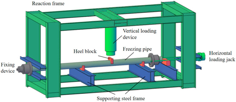
FIGURE 1. Experimental loading apparatus.
2.2 Sample parameters and structure
Selection of samples with the same material and specifications as the on-site frozen engineering, as well as identical joint processing methods, was made to replicate the construction conditions as closely as possible. The base material of the freezing pipe is a high-quality low carbon seamless steel pipe (20#), with a diameter of Φ159 mm and a wall thickness of 9 mm. The basic mechanical properties of the pipe material are shown in Table 1.

TABLE 1. Basic mechanical property indicators of pipe material.
The pipe sections were cut using mechanical cutting to minimize thermal damage and thermal stress. The experimental pipe sections, which included welded joints, were fabricated using an internal lining pipe and beveled butt welding (Figure 2). The length of the internal lining clamp was 80 mm. Compared to the external lining clamp joint configuration, this design reduced the number of joint seams by half, enhancing the reliability of the joints. The length of the experimental pipe section was determined as 4.2 m based on the dimensions of the experimental loading reaction frame. Both ends of the pipe section were welded with a variable diameter to facilitate the connection of the saline water circulation pipeline.
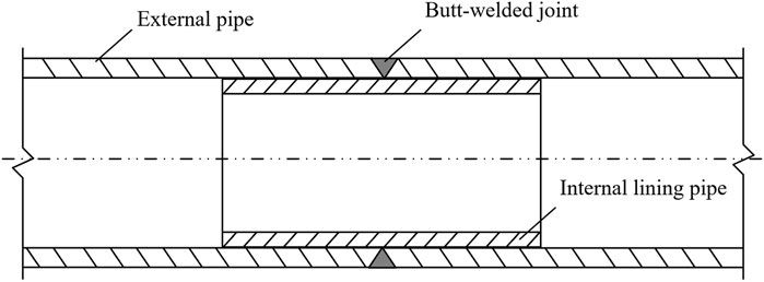
FIGURE 2. Structure of the internal lining pipe utilized with butt-welded joint.
2.3 Experimental procedure
The freezing pipe has a length of 2.5 m and a span of 1.8 m. The supports of the loading apparatus act as the fixed points of a simply supported beam. The load is applied at the midpoint, specifically at the welded joint of the freezing pipe, in a concentrated loading manner. Twelve strain gauges and one displacement gauge are installed on the upper and lower sides of the test pipe section. A load cell is mounted directly above the joint weld to measure the load applied to the freezing pipe joint. The load cell is connected to a data acquisition system (DT80G-dataTaker) to record the load data. To ensure uniform loading on the joint, a U-shaped groove is placed directly above the joint, and a layer of insulation material is inserted inside the U-shaped groove to avoid noise interference during loading, thus maintaining experimental accuracy. A thermocouple sensor is positioned at the middle of the pipe to monitor the surface temperature of the freezing pipe in real-time. In order to achieve rapid cooling of the freezing pipe and better simulate the on-site construction conditions, a layer of insulation material is specifically applied to the surface of the freezing pipe. To facilitate the circulation of saline water, which simulates the on-site saltwater circulation system, small variable-diameter openings are left at both ends of the pipeline.
The freezing pipe is loaded using a hydraulic oil pump as the power source. After each loading cycle, the instrument automatically records the data. Initially, the loading speed is relatively fast. As it approaches the yield deformation point, the loading rate gradually slows down. Yield deformation continues to develop at the point of concentrated force (the welding joint of the freezing pipe) until the joint fails or the pipe body becomes unstable, at which point the data collection stops. Additionally, an AE instrument is utilized to detect and record AE data during the experiment.
The measurement point layout of the freezing pipe is as shown in Figure 3. The strain gauges are labeled as ①–⑫, and (1)–(2) represent AE probes. The distance between each strain gauge and AE probe is 10 cm.
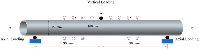
FIGURE 3. Schematic diagram of load measurement point layout for the freezing pipe.
2.4 Data monitoring
The data collection for freezing pipe strain, displacement, and load cell data is performed using the DT85 data logger with a sampling interval of 2 s. For AE experiments, the PCI-2 AE Detection System is used for AE monitoring. The sampling rate is set to 1MSPS (Mega Samples Per Second), with a sampling length of 2 k. The preamplifier gain is set to 40 dB, and the threshold values are adjusted based on specific experimental conditions. The sensor type used in this experiment is a resonant sensor (narrowband sensor), and its parameters are shown in Table 2.

TABLE 2. Parameters of the acoustic emission sensor.
The strain gauge data on the freezing pipe is collected in real-time using DT80G-dataTaker. Real-time calculations are performed to obtain the axial stress of the freezing pipe. Once the axial stress reaches the design value, vertical loading is applied until the freezing pipe fractures or reaches the maximum deformation limit.
3 Results
3.1 Mechanical performance of the freezing pipe
The experimental procedure employed hydraulic pressure controlled by an oil pump to regulate the loading speed, with the hydraulic pressure set at 0.2 MPa. The loading duration was approximately 600 s, and the load cell recorded a maximum load of around 240 kN. During the vertical loading process, the bending deformation of the pipe body exhibited a consistent trend with the vertical load curve. At the loading limit, the maximum bending deformation of the pipe body was approximately 150 mm (Figure 4).
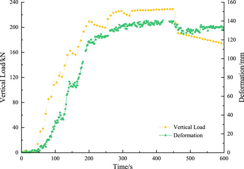
FIGURE 4. The loading and deformation process of the freezing pipe.
As the vertical load increases, the vertical displacement at the top surface of the freezing pipe steadily increases. However, the curve exhibits a parabolic shape (Figure 5), indicating that the deformation is a result of the combination of cross-sectional deformation (circular flattening into an elliptical shape) and bending deformation along the length of the pipe.
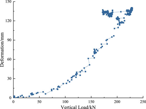
FIGURE 5. Load-deformation relationship of the freezing pipe.
The strain data from strain gauges 5 and 10 on the pipe body were selected to examine the stress distribution during loading (Figure 6). The calculations revealed that both the upper and lower surfaces of the pipe body were primarily under tension. When the vertical load was below 90 kN, the stress in the pipe body showed minimal variation. At this stage, the deformation was mainly due to compaction from the loading device and deformation in the radial direction at the loading point. As the vertical load continued to increase, the stress in the pipe body exhibited a linearly increasing trend. When the vertical load reaches approximately 230 kN, the loading cylinder reaches its maximum stroke. At this point, the strain gauge 5 on the pipe body experiences a stress of approximately 315 MPa, while the strain gauge 10 experiences a stress of approximately 450 MPa at its location.
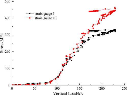
FIGURE 6. The stress curve of the freezing pipe under loading.
By examining the stress at the top surface of the pipe body at locations of strain gauges 8, 7, 5, and 4, the spatial stress distribution curve of the freezing pipe during the loading process is depicted (Figure 7). As the vertical load gradually increases, the curve transitions from a concave shape to a convex shape. Furthermore, during the initial stages of loading, the bending deformation and stress are relatively small near the loading point, primarily characterized by flattening and horizontal deformation. However, as the vertical load increases, the bending deformation of the pipe body becomes more significant, particularly at the loading point, where the deformation is greater compared to the distal end.
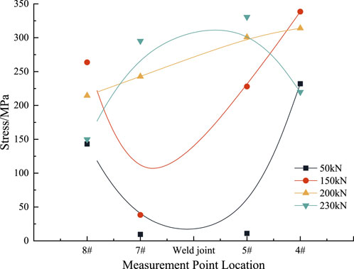
FIGURE 7. Spatial distribution patterns of stress in the freezing pipe under loading.
3.2 Pencil lead break signal testing
The freezing pipe was connected to a cold brine circulation system to test the sensitivity and reliability of the AE system under low-temperature conditions. The testing temperature was set at −28°C. From the characteristics of the AE amplitude, it can be observed that the AE testing system maintains good stability under low-temperature conditions (Figure 8). The amplitude of the AE signals ranges from 60 to 90 dB, which is comparable to the results obtained under room temperature conditions.
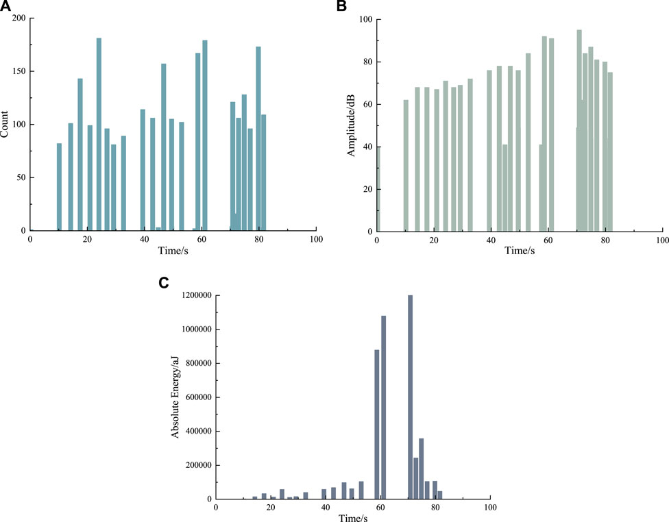
FIGURE 8. The characteristics of the pencil lead break signal under low-temperature conditions. (A) Acoustic emission count. (B) Amplitude of the acoustic emission signal. (C) Acoustic emission absolute energy.
Waveform data from three segments of the AE signals were selected for spectral analysis (Figure 9). From the observation of the AE waveform signals, they exhibit distinct burst signal characteristics. The spectral curve shows energy distribution in the frequency range of 6–50 kHz, with a peak around 47 kHz.
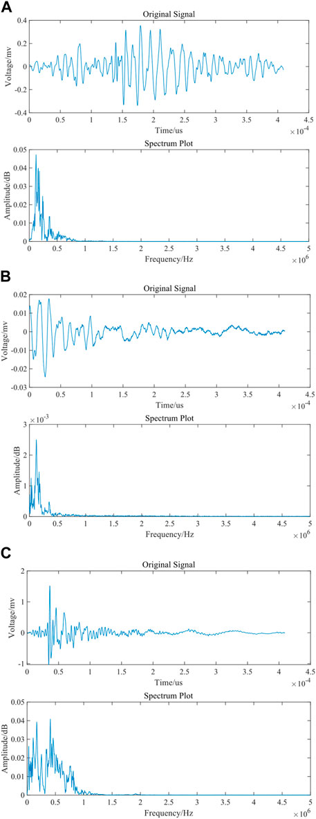
FIGURE 9. Waveform and spectral characteristics of the pencil lead break signal. (A) First segment. (B) Second segment. (C) Third segment.
3.3 Saltwater flow noise detection
In the operational state of a freezing pipe, low-temperature saltwater circulates within it, and the flow of saltwater creates interference noise through friction with the pipe wall. This noise mixes with the AE signals generated by the stress on the pipe material itself. It can be detected by the freezing pipe fracture monitoring system and interfere with the identification of critical signals related to pipe fracture. Therefore, it is necessary to identify the acoustic signal characteristics during saltwater flow. This will provide a basis for subsequent on-site AE signal detection, filtering, and signal processing.
In this saltwater noise detection experiment, an experimental section was designed to circulate low-temperature saltwater, simulating the operational state of a freezing pipe under field conditions. Subsequently, AE signals generated by the flow of saltwater in the freezing pipe were detected under unloaded conditions, obtaining AE characteristic parameters at different temperatures and saltwater pressures. Through pattern matching among multiple AE signal features and their mutual comparison, the detected AE signals were subjected to coupled extraction and comparative analysis of characteristic parameters. This process enables the identification of AE patterns corresponding to saltwater flow, leakage, and other states. The experimental section and connecting pipelines were insulated using polyurethane foam. Two AE measurement points were installed on the experimental section, and the pipe wall temperature was monitored using thermocouples.
Based on the experimental results, it was observed that normal saltwater flow within the freezing pipe generates continuous AE signals. The ringing count and energy remain stable within a certain range. The cumulative ringing count and energy exhibit linear growth, and the amplitude distribution is relatively uniform, consistently ranging between 40 and 43 dB (Figure 10). By detecting the normal flow of saltwater within the freezing pipe, it provides a basis for identifying signals related to saltwater leakage during pipe fracture.
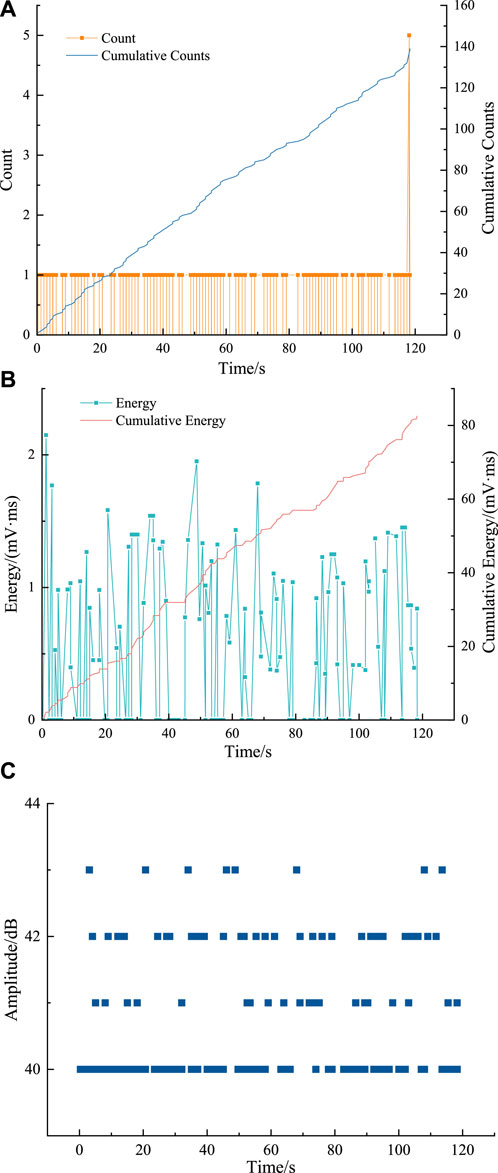
FIGURE 10. Saltwater flow noise test results. (A) Count-Time. (B) Energy-Time. (C) Amplitude-Time.
Three segments of typical waveform data from the saltwater flow during the AE signal were selected for spectral analysis (Figure 11). It can be observed that the saltwater flow signal exhibits continuous AE characteristics, which can be clearly distinguished from burst signals in the raw waveform. After Fourier transformation, the frequency components are concentrated in the range of 19.53–48.83 kHz.
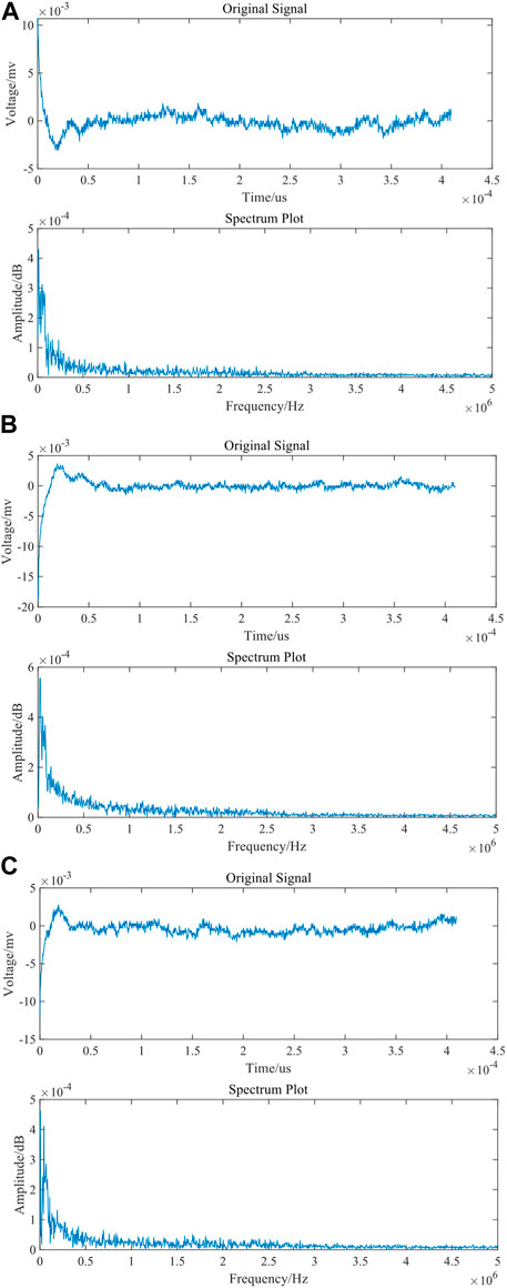
FIGURE 11. Spectral characteristics of saltwater flow noise. (A) First segment. (B) Second segment. (C) Third segment.
3.4 Acoustic emission signal characteristics of a loaded freezing pipe
The bending-tensile test of the freezing pipe had a duration of 650 s. At approximately 150 s into the test, a sharp and distinct sound was emitted. For this test, 11 strain gauges were used to measure the strain, and the maximum applied load was 227 kN. The AE threshold was set at 50 dB. Based on the results of the bending-tensile test on the freezing pipe (Figure 12), it is evident that the strain near the loaded section of the pipe is significantly higher than in other areas. The tensile strain on the loading side (Strain Gauge 10, approximately 60,000 με) is nearly twice the compressive strain on the opposite side (Strain Gauges 5 and 7, approximately 30,000 με). This indicates that tensile stress has a more pronounced effect on the deformation of the freezing pipe structure compared to compressive stress. These findings provide valuable insights for understanding the failure of welded joints in freezing pipes. As the pressure value increases, a significant number of AE signals are initially generated, mainly due to mechanical system noise. When the load reaches its maximum value and remains constant, there are no sudden bursts of AE signals. Instead, continuous signals are generated, indicating that the freezing pipe is in the plastic deformation stage. With the continuous increase in pressure, the deflection also increases. The maximum deflection reaches 138.9 mm, which is much larger than the deflection value of a regular freezing pipe. This demonstrates that the connection form of internal lining plus bevel groove welding greatly enhances the deformation capacity of the freezing pipe. The AE signals detected by the two channels show significant consistency and correlation. When the load increases linearly over time, the cumulative ringing count and cumulative energy exhibit linear consistency with the load growth. Furthermore, as the load increases, the magnitude of linear growth continues to increase.
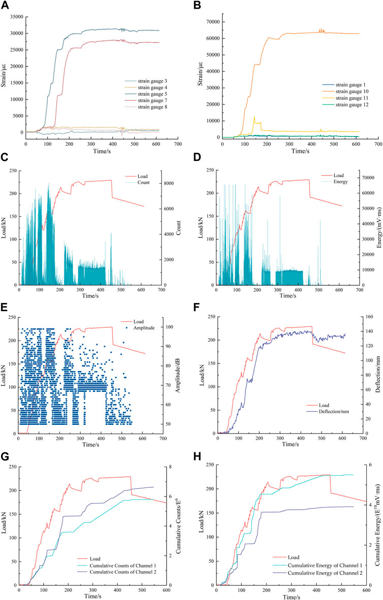
FIGURE 12. Results of the bending-tensile test on the freezing pipe. (A) Compressive strain. (B) Tensile strain. (C) Count. (D) Energy. (E) Amplitude. (F) Deflection. (G) Cumulative count. (H) Cumulative energy.
3.5 Acoustic emission signal characteristics of a fractured freezing pipe
The loading duration of the pre-notched freezing pipe fracture test was approximately 400 s with a threshold of 50 dB for AE signals. During the experiment, four distinct sound events were observed at 49, 112, 205, and 352 s, coinciding with the fracture occurrence at the welding joint of the freezing pipe. From the experimental data (Figure 13), it can be observed that the freezing pipe underwent significant plastic deformation, reaching a value of up to 160 mm. The compressive strain on the upper portion of the freezing pipe stabilized after reaching its peak pressure, while the tensile strain on the bottom side exhibited a certain correlation with pressure variations. This further supports the notion that the bottom portion of the freezing pipe under tension should be a critical focus area for research. Significant variations in pressure and tensile stress were observed at around 50, 115, 200, and 320 s. Concurrently, strong AE signals were detected around 50, 120, 200, and 340 s, indicating abrupt changes in the state of the freezing pipe at these instances. Furthermore, considering the substantial increase in cumulative count and cumulative energy around 100∼120 s, it can be inferred that the freezing pipe experienced failure during this period.
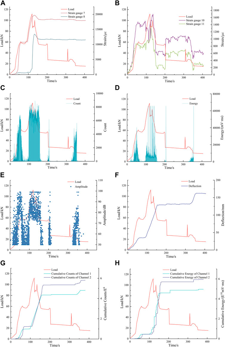
FIGURE 13. Results of the pre-notched freezing pipe fracture test. (A) Compressive strain. (B) Tensile strain. (C) Count. (D) Energy. (E) Amplitude. (F) Deflection. (G) Cumulative count. (H) Cumulative energy.
4 Conclusion
This study is based on AE technology and establishes an experimental system for the mechanical loading of freezing pipes and joints. We simulated the stress conditions of frozen pipes under different working conditions and investigated the AE signal characteristics of the mechanical performance and loading process of frozen pipes under low-temperature conditions.
With the presence of internal lining and clamps, freezing pipe joints can withstand higher loads and exhibit significant deformation capacity. The ultimate load-bearing capacity of the joints approaches the tensile limit of the pipe material, with a maximum deformation exceeding 120 mm. As the freezing pipe bears increasing loads, its deflection increases. However, the coordination of deformation between the joint and the freezing pipe becomes weaker. When the load eventually exceeds the strength of the joint, the joint fractures.
The flowing saltwater signal exhibits continuous AE signals, which can be distinctly differentiated from transient signals in the raw waveform. After performing Fourier transform for spectral analysis, the frequency components are concentrated within the range of 19.53–48.83 kHz.
During the elastic stage of the freezing pipe under tensile loading, the strain increases linearly with the increase in tensile stress. Significant AE signals are generated during this stage, accompanied by an increase in ringing count and energy. The cumulative ringing count also exhibits a linear growth characteristic with the increasing strain.
During the plastic deformation stage of the freezing pipe, there are no sudden bursts of AE signals. Most of the signals are continuous in nature. As the pressure continues to increase, the deflection of the pipe also increases, reaching a maximum deflection of 138.9 mm. The AE ringing count and energy remain relatively calm during this stage. The cumulative ringing count and cumulative energy curves exhibit a decreasing slope or even become flat, with amplitudes decreasing below 120 dB. The dominant frequency signal amplitudes of the AE during freezing pipe fracture are mainly concentrated around 50–90 dB and 160 dB. Prior to the fracture of the freezing pipe, the cumulative count and cumulative energy of the AE signals show a linear growth pattern. The maximum amplitude of the fracture signal can reach 220 dB.
By studying the changes in AE signals during the deformation and fracture of freezing pipes, it is possible to establish criteria based on AE for identifying the deformation process and the critical state of fracture in freezing pipes. These criteria provide a basis for the dynamic analysis of AE monitoring information, enabling the recognition of the mechanical deformation process and the early warning of fracture in freezing pipes.
Data availability statement
The original contributions presented in the study are included in the article/Supplementary Material, further inquiries can be directed to the corresponding author.
Author contributions
TW: Conceptualization, Formal Analysis, Funding acquisition, Methodology, Project administration, Resources, Supervision, Validation, Writing–original draft. WY: Conceptualization, Data curation, Formal Analysis, Methodology, Software, Validation, Writing–original draft. LL: Conceptualization, Funding acquisition, Methodology, Software, Supervision, Validation, Writing–review and editing.
Funding
The author(s) declare financial support was received for the research, authorship, and/or publication of this article. This research was funded by National Natural Science Foundation of China (Grant Nos 51874014, 52004015, and 52311530070), the fellowship of China National Postdoctoral Program for Innovative Talents (Grant No. BX2021033), the fellowship of China Postdoctoral Science Founda-tion (Grant No. 2021M700389), and the Fundamental Research Funds for the Central Universities of China (Grant Nos FRF-IDRY-20-003 and QNXM20210001).
Conflict of interest
The authors declare that the research was conducted in the absence of any commercial or financial relationships that could be construed as a potential conflict of interest.
Publisher’s note
All claims expressed in this article are solely those of the authors and do not necessarily represent those of their affiliated organizations, or those of the publisher, the editors and the reviewers. Any product that may be evaluated in this article, or claim that may be made by its manufacturer, is not guaranteed or endorsed by the publisher.
References
Banerjee, A., and Mukherjee, A. (2023). A mathematical algorithm for predicting the crack in the junction of a steel truss bridge using acoustic emission testing. Int. J. Steel Struct. 23 (3), 747–757. doi:10.1007/s13296-023-00727-1
Barat, V., Marchenkov, A., Ivanov, V., Bardakov, V., Elizarov, S., and Machikhin, A. (2021). Empirical approach to defect detection probability by acoustic emission testing. Appl. Sci. 11 (20), 9429. doi:10.3390/app11209429
Chen, X. (2012). A space-time-dependant design method and the stability of ice wall for deep shafts. Appl. Mech. Mater. 1975, 3275–3281. doi:10.4028/www.scientific.net/AMM.204-208.3275
Cui, H., Li, W., and Wang, H. (2011). The mechanics experimental study of the artificially frozen soil in cretaceous strata. Appl. Mech. Mater. 1447, 1844–1847. doi:10.4028/www.scientific.net/amm.94-96.1844
Deng, S., He, Y., Yang, M., Zhou, F., Liu, H., Zhu, R., et al. (2023). Numerical analysis of shield tunnelling breakthrough working shaft by artificial ground freezing method under extreme conditions considering phase change latent heat. Appl. Sci. 13 (6), 3651. doi:10.3390/app13063651
Han, J., Wang, J., Cheng, C., Zhang, C., Liang, E., Wang, Z., et al. (2023). Mechanical response and parametric analysis of a deep excavation structure overlying an existing subway station: a case study of the Beijing subway station expansion. Front. Earth Sci. 10, 1079837. doi:10.3389/feart.2022.1079837
Hase, A., Morita, M., and Onodera, K. (2023). Analysis of seizure-resistance-improvement mechanism of polymer additives by acoustic emission sensing. Tribol. Int. 184, 108441. doi:10.1016/j.triboint.2023.108441
Jing, L., Gao, Q., and Yang, R. (2004). Fracture stress analysis and fracture position determination of freezing pipe. Min. Metall. Eng. 24 (4), 9–12.
Li, J., Wang, Y., Li, D., and Zhang, C. (2011). Model tests on stress and deformation of freezing-pipes during multi-circlefreezing before excavation. Chin. J. Geotech. Eng. 33 (7), 1072–1077.
Li, T., Zhao, W., Liu, R., Han, J., Jia, P., and Cheng, C. (2023). Visualized direct shear test of the interface between gravelly sand and concrete pipe. Can. Geotech. J. 2023. doi:10.1139/cgj-2022-0007
Ma, Y., Liu, M., Yang, L., Dai, P., and Fan, J. (2023). Damage analysis of concrete-filled square stainless steel columns based on acoustic emission and Markov chain methods. Eng. Struct. 281, 115730. doi:10.1016/j.engstruct.2023.115730
Prokop’ev, L. A., Andreev, Ya. M., and Lukin, E. S. (2023). Assessing hazard degree of crack-like defects based on acoustic emission testing under local low-temperature loading. Russ. J. Nondestr. Test. 58 (12), 1064–1070. doi:10.1134/S1061830922700103
Sheng, Y. (2009). On the reasons for brine intake fractured and ways to prevent brine intake fractured. Coal Tech. 28 (7), 176–177.
Sohaib, M., Islam, M., Kim, J., Jeon, D. C., and Kim, J. M. (2019). Leakage detection of a spherical water storage tank in a chemical industry using acoustic emissions. Appl. Sci. 9 (1), 196. doi:10.3390/app9010196
Wang, T., Yue, F., Jiang, Y., and Zheng, T. (2010). Research and practice on forced thaw technology applied to frozen wall of mine shaft. J. China Coal Soc. 35 (6), 918–922. doi:10.13225/j.cnki.jccs.2010.06.010
Wu, X., and Lin, S. (1992). Research on the flexible connectors for freezing pipes. J. China Univ. Min. Technol. 21 (1), 51–56.
Yang, R., Fu, X., Yang, L., Li, X., Chen, Q., Chen, C., et al. (2016). Research on the shaping control of frozen wall and blasting vibration mitigation of shaft wall effect in mine vertical shaft. J. China Coal Soc. 41 (12), 2975–2985. doi:10.13225/j.cnki.jccs.2016.1487
Yang, W., Du, Z., Yang, Z., and Bo, D. (2013). Plastic design theory of frozen soil wall based on interaction between frozen soil wall and surrounding rock. Chin. J. Geotech. Eng. 35 (10), 1857–1862.
Yang, Y., Lai, Y., and Li, J. (2009). Laboratory investigation on the strength characteristic of frozen sand considering effect of confining pressure. Cold Reg. Sci. Technol. 60 (3), 245–250. doi:10.1016/j.coldregions.2009.11.003
Zhang, J. (2008). Experimental study of mechanical characteristics of frozen steel pipe under normal temperature and low temperature. Coal Tech. 27 (12), 102–103.
Zhang, W., Hu, X., Wang, Y., and Yue, F. (1989). Microcomputerized alarm system for freezing pipe rupture. J. China Univ. Min. Technol. 18 (3), 46–53.
Zhang, W., Hu, X., Wang, Y., and Yue, F. (1990). Research on the experimentation for obtaining freezing pipe rupture signal. J. China Univ. Min. Technol. 19 (3), 76–80.
Zhao, X., Zhou, G., and Chen, G. (2013). Triaxial compression strength for artificial frozen clay with thermal gradient. J. Cent. South Univ. 20 (1), 218–225. doi:10.1007/s11771-013-1479-x
Zheng, Z., Xu, Y., Dong, J., Zong, Q., and Wang, L. (2015). Hard rock deep hole cutting blasting technology in vertical shaft freezing bedrock section construction. J. Vibroeng. 17 (3), 1105–1119.
Zhou, X. (1996). Stressing of freeze pipe in the deformed section of ice wall. J. China Coal Soc. 21 (1), 30–34.
Keywords: acoustic emission, fracture, freezing pipe, spectrum, mechanical deformation
Citation: Wang T, Ye W and Liu L (2023) Study on the mechanical properties and acoustic emission signal characteristics of freezing pipe. Front. Earth Sci. 11:1298025. doi: 10.3389/feart.2023.1298025
Received: 21 September 2023; Accepted: 06 November 2023;
Published: 27 December 2023.
Edited by:
Jianyong Han, Shandong Jianzhu University, ChinaCopyright © 2023 Wang, Ye and Liu. This is an open-access article distributed under the terms of the Creative Commons Attribution License (CC BY). The use, distribution or reproduction in other forums is permitted, provided the original author(s) and the copyright owner(s) are credited and that the original publication in this journal is cited, in accordance with accepted academic practice. No use, distribution or reproduction is permitted which does not comply with these terms.
*Correspondence: Liyuan Liu, bGl1bGl5dWFuQHVzdGIuZWR1LmNu