 Keyue Zheng
 Chenghua Shi
 Qianjin Zhao3,4
 Mingfeng Lei
 Chaojun Jia
94% of researchers rate our articles as excellent or good
Learn more about the work of our research integrity team to safeguard the quality of each article we publish.
Find out more
ORIGINAL RESEARCH article
Front. Earth Sci., 29 December 2023
Sec. Geohazards and Georisks
Volume 11 - 2023 | https://doi.org/10.3389/feart.2023.1289251
This article is part of the Research TopicEvolution Mechanism and Control Method of Engineering Disasters Under Complex EnvironmentView all 30 articles
Squeezing deformation in tectonic fracture zones under high in-situ stresses has created great difficulties to deep tunnel construction in Southwestern China. This study reports an investigation on large deformation and failure mechanisms of the Wanhe tunnel on the China-Laos Railway through several field tests including the in-situ stress, loosened zone, deformation monitoring, and internal stresses of steel arches. The dynamic process control method is proposed following the combination principle of stress releasing and support resistance. Further, the dynamic process control measures including the advanced and primary supports, the deep-shallow coupled delayed grouting method, and the double steel arches method were applied on site to resist the deformation development. The results of this study indicate that the rapid growth of the tunnel deformation in the early stage was caused by the squeezing effect, and later the loosening effect led to another growing trend of the vault settlement. The dynamic process control method allows to release the deformation of the surrounding rock in the rapid growth stage. Then, it requires to control the deformation within the reserved range by reinforcing the surrounding rock and increasing the stiffness of supports in the later stage. From the feedback of monitoring results, large deformation of Wanhe tunnel was well released and effectively controlled within the deformation allowance. Thus these countermeasures based on the dynamic process control method can guarantee the construction safety of deep buried tunnels in tectonic fracture zones under high in-situ stresses.
For soft rock with an uniaxial compressive strength below 25 MPa (Ulusay, 2015), squeezing will cause large deformation under high geostress, which has been a difficult challenge in the construction of deep soft-rock tunnels for a long time. Typical squeezing tunnels in the world mainly include the Enasan highway tunnel in Japan (Kimura et al., 1987), the Tauern railway tunnel (Ayaydin and Leitner, 2009; Franz and Harald, 2009) and the Arlberg tunnel (John, 1980) in Austria, the Gotthard railway tunnel (Mezger et al., 2013) and the Simplon tunnel (Milnes, 1973) in Switzerland, the Lyon-Turin Base Tunnel (Bonini and Barla, 2012) connecting Italy and France, Y-Basque high-speed railway tunnels in northern Spain (Iasiello et al., 2021), etc. In China, most of the squeezing tunnels appear in the west, such as the Jiazhuqing tunnel (Zhang, 1997) on Nanning-Kunming Railway, the Wushaoling tunnel (Yang et al., 2006) on Lanzhou-Xinjiang Railway, the Guanjiao tunnel (Wan et al., 2014) on Qinghai-Tibet Railway, the Muzhailing tunnel (Zhang et al., 2010; Wu et al., 2015) on Lanzhou-Chongqing Railway, the Baozhen tunnel (Li et al., 2013) on Yichuan-Wanzhou Railway, etc. A large number of monitoring data from these projects showed that the squeezing deformation had the characteristics of large magnitude, large rate, and long duration, which led to the failure of the tunnel supports and even affected the operation stage.
Large squeezing deformation on site is difficult to control during tunnel construction. Generally, the controlling principles of large deformation include the stress releasing principle, the support resistance principle, and the combination principle of stress releasing and support resistance. The representative of stress releasing principle is the New Austrian tunneling method (NATM), which emphasizes the use of flexible support to release the rock deformation energy and make the most strength of rock mass itself so as to reduce the deformation load acting on the support structures (Jeong et al., 2014; Cao et al., 2018). Methods followed this principle mainly include increasing the reserved allowable deformation (Vrakas and Anagnostou, 2016; Guan et al., 2020; Zhang D. L. et al., 2022), driving the energy-absorbing rock bolts into the soft rock mass (VandeKraats and Watson, 1996; Li et al., 2014), arranging a compressible layer between rock and lining (Wang et al., 2012; Wu et al., 2018; Tian et al., 2021; Zhang Q. et al., 2022), using yielding supports such as steel arches with sliding connections (Cantieni and Anagnostou, 2009; Horyl et al., 2013; Rodríguez and Díaz-Aguado, 2013) or shotcrete lining with highly deformable elements (Radoncić et al., 2009; Barla et al., 2011; Schubert et al., 2018; Tian et al., 2018). However, for soft rock tunnel under high in situ stress, using only the controlling principle of stress releasing will easily lead to the plastic yielding and failure of the surrounding rock (Tian et al., 2016; Tan et al., 2017; Cao et al., 2018). Conversely, the purpose of the support resistance principle is to restrain the squeezing deformation energy of the soft rock. Methods following this principle can be categorized as active control and passive control based on different supporting mechanisms (Wu et al., 2021). Active control refers to improving the bearing capacity of the surrounding rock, which can be implemented in two ways. One is arranging advanced supports such as small pipes and pipe roofs before tunnel excavation (Deng et al., 2022). The other is reinforcing the surrounding rock after excavation by grouting (Kang et al., 2021) or applying strengthened rock bolts (Wu et al., 2020; Sun et al., 2021). Passive control refers to strengthening the supporting structures to restrain rock deformation. Common methods following the passive format include thickening the shotcrete (Mezger et al., 2017), using heavy steel arches (Tan et al., 2022), reducing the arch spacing, supplementing additional layers of the initial lining (Chen et al., 2019), applying new types of supporting structures with high strength (Wang et al., 2017; Wang et al., 2018), etc. However, to resist the deformation load of the squeezing rock, common supports have limited bearing capacity. Many engineering cases following the resistance principle showed that heavy supports frequently failed to restrain large squeezing deformation and eventually needed a large amount of repairs during tunnel construction (Kimura et al., 1987; Ortlepp and Stacey, 1998; Aksoy et al., 2012). Using only the controlling principle of support resistance is considered uneconomical and impractical (Wu et al., 2021). Therefore, for soft-rock tunnels under high in situ stress, the control of the large squeezing deformation ought to be based on the combination principle of stress releasing and support resistance. This means that it is necessary to not only allow the rock mass deformation to exert its bearing capacity, but also to prevent the rock failure and control the deformation within the reserved range by reinforcing the surrounding rock or strengthening support structures. This can be defined as the principle of dynamic process control, which means that the development of squeezing deformation should be controlled in process. However, there are few tunneling cases following this principle in the existing research. Most squeezing tunnels were still finished through multiple removals of supports, re-profiling of tunnel sections and design changes, which greatly increased the engineering cost and delayed the construction period.
In recent years, as an important part of the Belt and Road Initiative, the Sichuan-Tibet Railway (Zhang C et al., 2022) and the Trans-Asian Railway (Rowedder, 2020) are under construction. There are more and more tunnelling projects in southwestern China. The tectonic movement of plates in the Southwest (especially the Yunnan-Guizhou Plateau) is complex, which causes strong tectonic stress accumulated in deep formation (Qiao et al., 2022; Wang et al., 2022). Joints and faults are formed when the rock formations are damaged by the squeezing of tectonic stresses (Zhang Q. et al., 2022; Lin et al., 2023; Ma et al., 2023). Deep rock masses in these geological structures are broken with developed fractures and poor integrity, which is called the tectonic fracture zone. Due to poor self-stabilization ability and high in-situ stresses field, severe squeezing deformation easily occurs during the tunnel construction. The China-Laos railway is an important part of the TAR (Trans-Asian Railway) plan, which connects Kunming in China and Vientiane in Laos. The Wanhe tunnel of the China-Laos railway from DK32+100 to DK32+725 passes through a tectonic fracture zone, which was the broken Yanshanian granite strata with well-developed fractures and in the shape of breccia. The maximum burial depth of the tunnel is more than 500 m. Serious deformation was encountered during construction. In this paper, the Wanhe railway tunnel was presented as a case study to discuss deformation characteristics and failure mechanisms of deep buried tunnels in tectonic fracture zones under high in-situ stresses. Further, this paper proposed the countermeasures of large deformation based on the dynamic control principle and process, which can provide a reference for similar tunnel construction in tectonic fracture zones under high in-situ stresses.
The China-Laos railway connecting Kunming, China and Vientiane, Laos is an important part of the TAR (Trans-Asian Railway) plan, which is of great significance for China to implement the Belt and Road strategy and promote the development of the ASEAN Free Trade Area. The railway section in China starts from Kunming, Yunnan Province and ends at the Mohan on the China-Laos border, with a total length of 507 km. The Wanhe tunnel is located between the Eshan Station and Luoli Station, which is the second longest tunnel of the China-Laos railway with a length of 17.44 km. The starting and ending points of the tunnel are located at DK22+468 and DK39+909. Figure 1 shows the locations of the China-Laos railway and the Wanhe tunnel. The Wanhe tunnel is a double-track railway tunnel with a large section. The height and span of the tunnel are respectively 12.03 m and 12.96 m. The composite lining is used as the tunnel support system, which contains primary support, waterproofer, and secondary lining (shown in Figure 2). Figure 3 shows the geological conditions in the longitudinal sections of the Wanhe tunnel. The maximum buried depth of this tunnel is about 586 m. The Wanhe tunnel passes through two active fault zones, which are a reverse fault called Gongjipo and a normal faultnamed Lijiashan. The surrounding rock of the Wanhe tunnel is severely affected by the tectonic movement with developed faults and folds. The lithological characters of Wanhe tunnel consist of slate interbedded with sandstone, granite, sandstone interbedded with shale, mudstone interbedded with sandstone, and Quartz diorite. Laboratory experiments were conducted on core samples taken from core drilling. The mechanical properties of rock units, including density, uniaxial compressive strength, Young’s modulus, and Poisson’s ratio, are presented in Table 1.
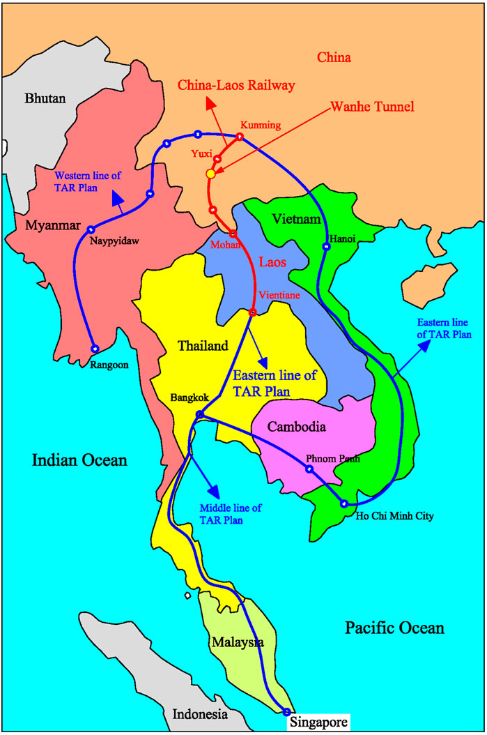
FIGURE 1. Locations of the China-Laos railway and the Wanhe tunnel.
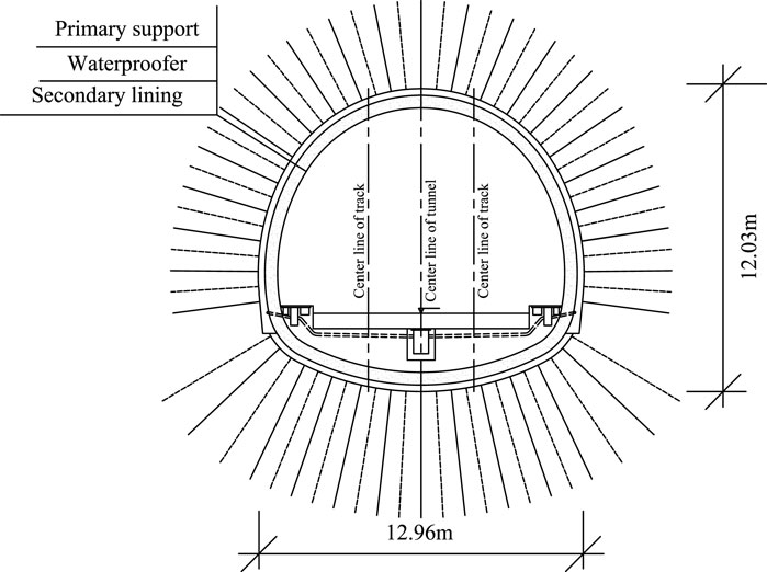
FIGURE 2. Cross section of the Wanhe tunnel.
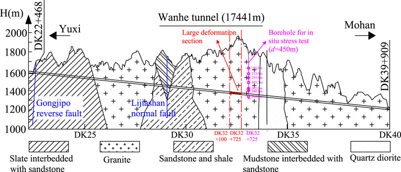
FIGURE 3. Geological conditions in the longitudinal sections of the Wanhe tunnel.
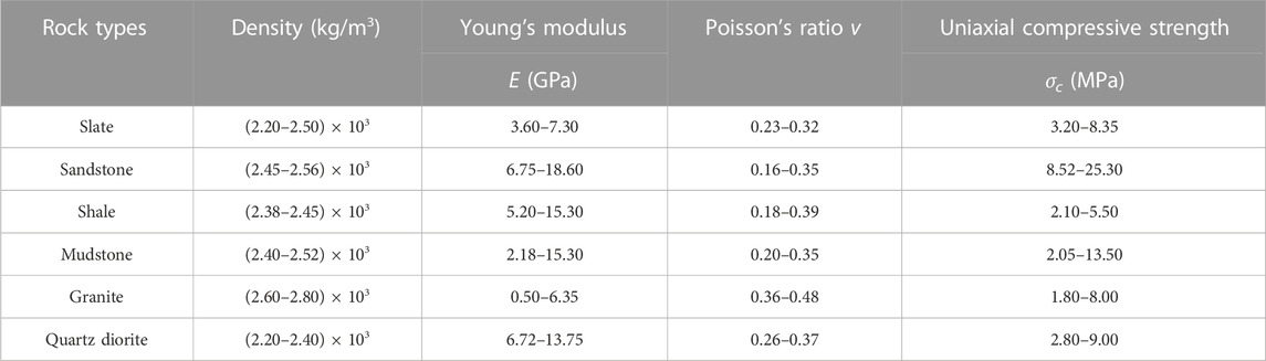
TABLE 1. Physico-mechanical parameters of rock units.
From July 2018 to March 2019, during the construction of the Wanhe tunnel from DK32+725 to DK32+100, large deformations frequently occurred at the vault and side wall. This section was excavated by the three-bench-step method and was supported with shotcrete, anchor bolts, steel arches, and lock-foot anchor pipes. According to the on-site monitoring of the railway section from DK32+475 to DK32+415, the maximum vault settlement reached 763.9 mm, and the maximum horizontal convergence reached 720.2 mm, which exceeded the deformation allowance and caused the cracking of shotcrete and the bending of steel arches. Failure problems of the primary supports on site are shown in Figure 4. The exposed stratum during the excavation of this heavily deformed section was the broken granite with well-developed joints, which is mostly in the shape of breccia as shown in Figure 5. Affected by complex tectonic movement, the originally hard granite in the deep (with the burial depth of nearly 500 m) was squeezed into broken rock mass with poor self-stabilization ability, which was easy to fail especially under high in-situ stresses during tunnel excavation.

FIGURE 4. Typical diseases of large deformation. (A) Shotcrete cracked. (B) Steel arches were twisted.
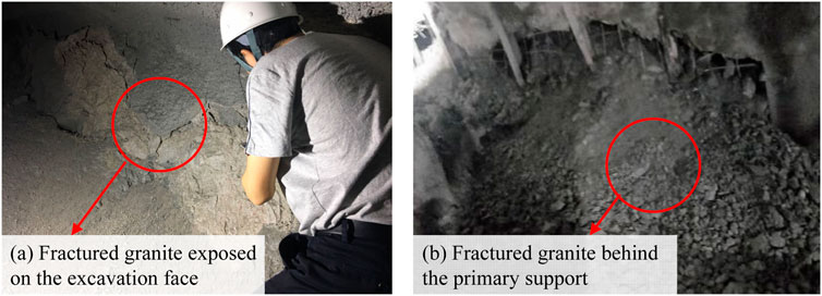
FIGURE 5. Rock mass of large deformation sections. (A) Fractured granite exposed on the excavation face. (B) Fractured granite behind the primary suppor.
The level of in situ stress is an important factor causing large deformation of tunnels. To explore whether the failure of the Wanhe tunnel was induced by high geostress or not, in situ stress test using the hydraulic fracturing method was conducted before the tunnel construction. Figure 6 shows the test principle of the hydraulic fracturing method (International society for rock mechanics, 1987). σH represents the maximum horizontal principal stress around the borehole, and σh is the minimum horizontal principal stress. It can be deduced that the tangential stress (σθ) around the borehole in the direction of σH is 3σh-σH. When the hydraulic pressure exceeds the sum of the tangential stress (σθ) and the rock tensile strength (Rt), the borehole wall will be fractured. Thereby, define the hydraulic pressure at this time as the initial fracturing pressure Pi with the formula as Eq. 1. Then, re-pressurize the borehole wall to make the fracture open again, and define the pressure at this time as the fracture reopening pressure Pr, which is equal to the tangential stress σθ (Eq. 2). When the fracture depth exceeds 3 times the borehole diameter, the hydraulic pressure will remain steady. It can be defined as the steady pressure Ps, which is equal to the in situ stress σh as shown in Eq. 3. By combing the Eqs 1–3, the maximum horizontal principal stress (σH) and minimum horizontal principal stress (σh) can be solved. After fracturing, use a directional imprinting machine to record the length and direction of the fractures. Thus the direction of the maximum horizontal principal stress can be obtained.
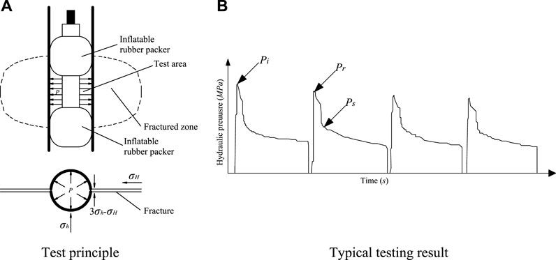
FIGURE 6. Test principle of the hydraulic fracturing method. (A) Test principle. (B) Typical testing result.
A borehole at DK33+58 with a depth of 450 m was drilled on site with the location shown in Figure 3, which is close to the tunnel section suffered large deformation. Figure 7 is the photo of the drilling on site. Seven measuring points at depths of 155.0 m, 213.0 m, 255.0 m, 303.7 m, 365.2 m, 389.1 m, and 444.0 m were selected for the test respectively. The directions of the maximum horizontal principal stress at depths of 303.7 m and 444.0 m were tested after fracturing. Table 2 shows the testing results of the borehole at DK33+58. In addition, the vertical stress (σv) is calculated according to the gravity of the rock mass. Figure 8 shows the distribution of stress with depth. The direction of the fractures at the depth of 444 m recorded by imprinting is shown in Figure 9. Thus, the distribution rules and characteristics of the in situ stress in the Wanhe tunnel can be summarized as follows:
(1) The horizontal principal stress increases almost linearly with depth, except for the test point at the depth of 300 m. For measuring points with a depth less than 400 m, the magnitudes of three principal stresses show the characteristics of “σv >σH> σh,” which indicates that the in-situ stress field is dominated by the gravity of the rock mass. This is because the shallow soft rock mass can release the horizontal principal stress through rock deformation. The ratio of the maximum horizontal principal stress (σH) to the vertical stress (σv) is defined as the maximum lateral coefficient (Kv), which is mainly in the range of 0.6–0.8 for those testing points within the depth of 400 m. It can be noticed that the horizontal principal stress tested at the depth of 300 m is greater than the vertical stress with a maximum lateral coefficient of 1.6. The reason for this is that the shallow strata were affected by unloading, denudation, and weathering for a long time, which led to complex horizontal stress distributions. For measuring points with a depth greater than 400 m, the magnitudes of three principal stresses show the characteristics of “σH >σv> σh,” and the maximum lateral coefficient ranges from 1.1 to 1.3. This indicates that the tectonic stress increases with depth and is dominant in the deep in situ stress field.
(2) The imprints of the fractures tested by the directional stamping machine are clear enough. It can be seen in Figure 9 that the fractures are vertical and symmetrical. The directions of the maximum horizontal principal stress at the depths of 303.7 m and 444.0 m are N33°W and N50°W, respectively, which is close to the trend of two active fault zones that the Wanhe tunnel passes through. This indicates that the directions of the maximum horizontal principal stress tested on site can represent the direction of the tectonic stress field. In addition, the direction of the maximum horizontal principal stress is nearly parallel to the direction of the tunnel axis with a small intersection angle, which indicates that the deformation of the tunnel section mainly depends on the minimum horizontal principal stress and vertical stress.
(3) The measuring point at the depth of 444 m is close to the large deformation section of the Wanhe tunnel. The maximum horizontal principal stress, minimum horizontal principal stress, and vertical stress at this point are 15.31 MPa, 10.92 MPa, and 11.77 MPa, respectively. In situ stress at this depth is dominated by horizontal tectonic stress. According to uniaxial compressive strength testing results of rock specimens, the uniaxial compressive strength (Rc) of soft granite at the large deformation section is 1.8 MPa. Thus the ratio of the uniaxial compressive strength (Rc) to the maximum principal stress (σmax) is 0.12. In accordance with code for design on railway tunnels in China [TB10003—2016, (Code for design on railway tunnel, 2017)], the region with such a strength-stress ratio is located in a high ground stress area, which can easily lead to large squeezing deformation of surrounding rock.
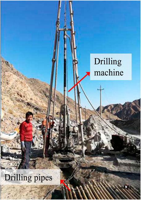
FIGURE 7. Borehole drilling on site.
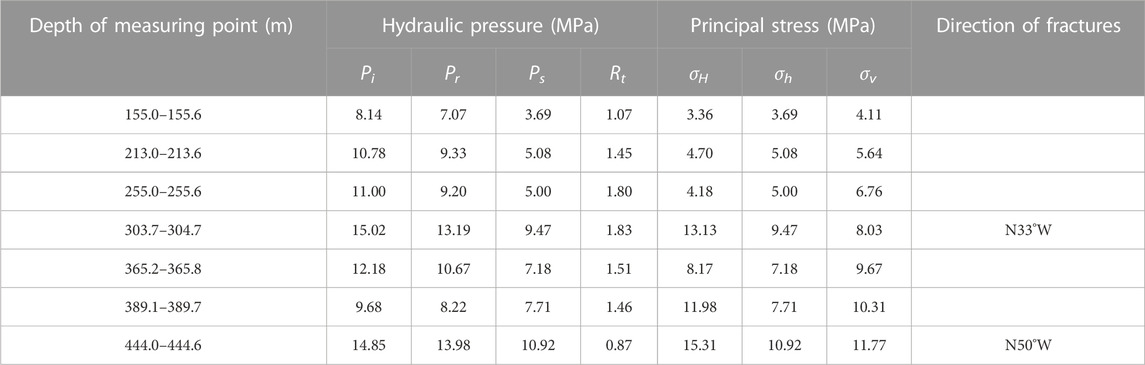
TABLE 2. Testing results of in situ stress by hydraulic fracturing method.
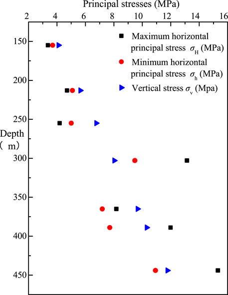
FIGURE 8. Distribution of principal stresses with depth.
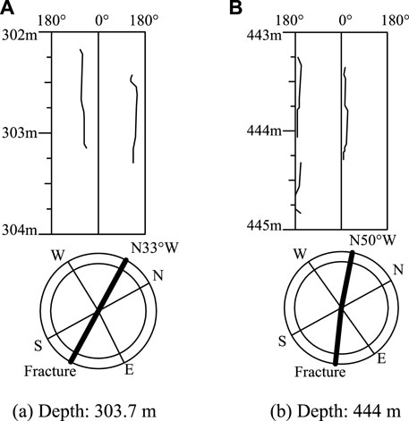
FIGURE 9. Direction of the fractures recorded by stamping. (A) Depth: 303.7 m. (B) Depth: 444 m.
Tunnel excavation will induce stress redistribution, plastic deformation, and fracture propagation in the surrounding rock, thus resulting in a loosened zone around the tunnel. Especially for deep soft rock tunnels under high in-situ stress, expansion of the loosened zone will further worsen the development of tunnel deformation. Therefore, the extent of the loosened zone is an important factor affecting the squeezing deformation. To assess the loosened zone of the Wanhe tunnel, ultrasonic wave testing was conducted after tunnel excavation. Since the wave speed depends on the strength of the medium, the ultrasonic wave propagates more slowly in the loosened zone with soft and broken rock (Chen et al., 2015; Xu et al., 2018). The test principle and specific test process are shown in Figures 10, 11.
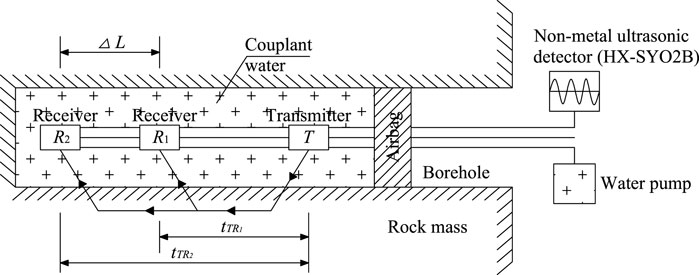
FIGURE 10. Test principle of loosened zone.
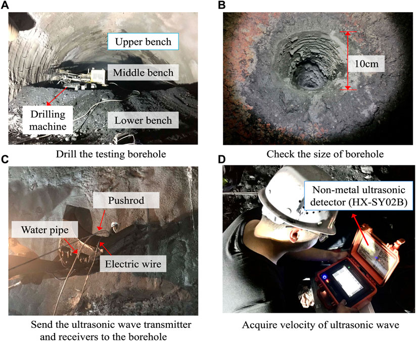
FIGURE 11. Test process of loosened zone on site. (A) Drill the testing borehole. (B) Check the size of borehole. (C) Send the ultrasonic wave transmitter and receivers to the borehole. (D) Acquire velocity of ultrasonic wave.
Firstly, drill several boreholes from the tunnel section to the deep by using the drilling machine of the pipe roof. Then, send the ultrasonic wave transmitter and receivers to the hole bottom, and inject water into this area as one kind of couplant. After that, the ultrasonic wave was emitted from the transmitter by operating the non-metal ultrasonic detector and received by two receivers after propagating in the rock mass. Thus the velocity of the ultrasonic wave (vp) can be determined by Eq. 4, of which the △L is the distance between two receivers and the tTR is the time when the receivers pick up the ultrasonic wave. By moving the transmitter and receivers 0.2 m each time from the bottom to the entrance and repeating the above steps, the wave velocity of surrounding rock at different borehole depths can be obtained. Ultrasonic waves propagate with lower velocity in soft media. Therefore, the wave speed in the loosened zone is lower than in other regions of the surrounding rock. According to Tan’s research (Tan et al., 2022), the depth of the loosened zone at this borehole is the section with a lower average wave velocity.
The Wanhe tunnel was excavated by the three-step method. Six boreholes with a depth of 20 m and a diameter of 10 cm were drilled in each test section of the tunnel. These boreholes were respectively located at both sides of the steps, with a distance of 1.8 m from the hole center to the step boundary. Since the drilling machine of the pipe roof cannot drill the deep hole at the vault, the depth of the loosened zone at the vault was estimated as the average of the testing results at the upper bench. Due to the hole collapse at the bottom, the maximum depth that the transmitter can reach was about 16–18 m on site. The distribution curve of the wave velocity with the hole depth at the DK32+460 section is shown in Figure 12, which was tested 45 days after excavation. Thus, the distribution characteristics of the loosened zone can be summarized as follows:
(1) By taking the testing results of borehole A2 as an example, the evaluation process of the loosened zone depth is introduced. The borehole A2 is located on the right side of the upper step, and the maximum testing depth was 16.0 m. According to the testing results, the wave velocity at the depth of 14.4 m is the largest reaching 2.923 km/s. There was severe velocity fluctuation in the depth range of 0 m–12.6 m, which was mainly caused by weak rock mass or discontinuous fractures. However, when the testing depth exceeded 12.5 m, the wave velocity increased significantly. The average wave velocity in the depth range of 0 m–12.6 m was 0.476 km/s, which reached 1.887 km/s in the depth range of 12.6 m–16.0 m. Thus, based on the average wave velocity, it can be indicated that the depth of the loosened zone at the A2 is 12.6 m. Based on this evaluation method, the depths of the loosened zone at other boreholes are respectively considered as 11.6 m (A1), 9.0 m (B1), 14.0 m (B2), 4.0 m (C1), and 6.8 m (C2).
(2) According to the testing results of the wave velocity, the loosened zone boundary of the surrounding rock at the DK32+460 section can be obtained as shown in Figure 12. It can be seen that the maximum depth of the loosened zone is 14.0 m, which is located at the right side of the middle step. In contrast, the loosened zone depth at the left side wall is only 4.0 m. In addition, the loosened zone area on the right side of the surrounding rock is slightly larger than that on the left side. The gravity of the loosened rock mass will directly apply to the supporting structure, which will further worsen the development of tunnel deformation.
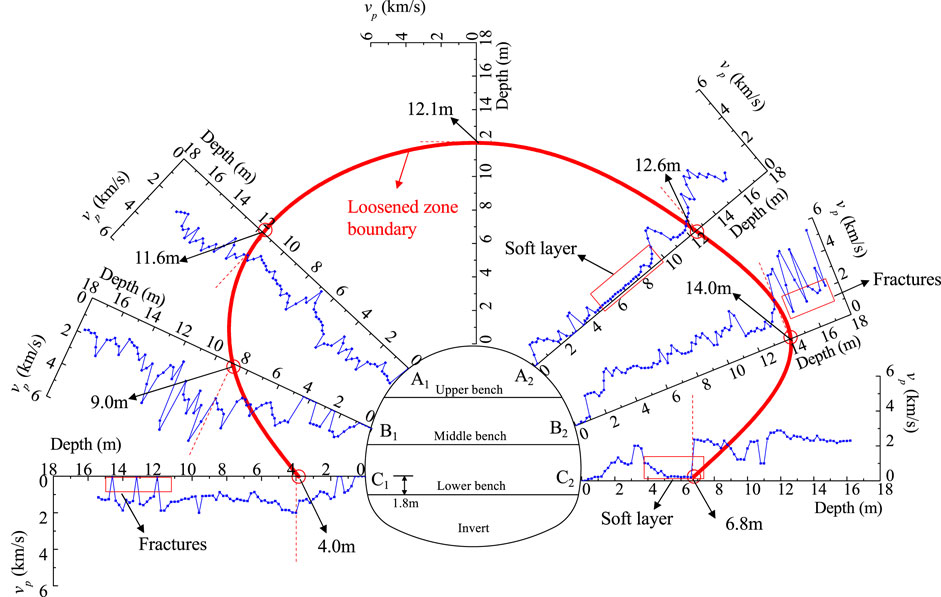
FIGURE 12. Loosened zone of the Wanhe tunnel tested on site.
The monitoring plan was implemented immediately to measure the vault settlement and horizontal convergence when the Wanhe tunnel suffered large deformation. On-site monitoring was carried out at least once a day and lasted for nearly 3 months, so as to obtain the whole process of the deformation development. Figure 13 shows the evolution curves of deformation and deformation rate at section DK32+460 of the Wanhe tunnel. Point V1 is the monitoring point for vault settlement. Line A1-A2, B1-B2, and C1-C2 are respectively used for monitoring the side wall convergence at the upper bench, middle bench, and lower bench. According to the monitoring results, the tunnel deformation characteristics are presented as follows:
(1) The evolution of vault settlement had gone through three stages, namely, the rapid growth stage, the slow growth stage, and the secondary growth stage. After the excavation of the upper bench, the vault settlement (Point V1) increased rapidly within 20 days, while the maximum deformation rate of which reached 100.5 mm/d on the 17th day. After 20 days, the deformation rate decreased significantly and entered the slow growth stage with a maximum deformation rate of 11.1 mm/d. However, on the 33rd day, the deformation rate of the vault showed another growth trend, which reached 69.6 mm/d. Since 50 days after the excavation of the upper bench, the accumulative vault settlement at section DK32+460 reached 763.9 mm, which far exceeded the allowable deformation and caused cracking of the vault shotcrete.
(2) The horizontal convergence was most severe at the side wall of the middle bench, which increased significantly within 20 days after excavation. Then the horizontal convergence increased slowly with decreased deformation rate. After 30 days of middle bench excavation, the horizontal convergence remained constant with the accumulated value of 720.2 mm, which caused the side wall cracking and bending of steel arches. The accumulated horizontal convergences at the side wall of the upper bench and the lower bench respectively reached 498.3 mm and 399.6 mm.
(3) The entire deformation of the section at DK32+460 showed an obvious deformation characteristic of “vault settlement > middle bench convergence > upper bench convergence > lower bench convergence”. The magnitude of the vault settlement is close to the middle bench convergence, which indicated that there is severe tectonic stress in the formation. In addition, the deformation development has the characteristics of the large growth rate and long duration in the early stage. In the later stage, the deformation development of vault settlement showed another growth trend with an increase of the deformation rate.
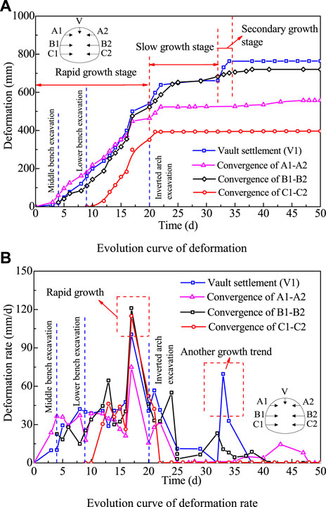
FIGURE 13. Deformation curve of DK32+460 section. (A) Evolution curve of deformation. (B) Evolution curve of deformation rate.
Strain gauges are arranged at DK32+460 section to monitor the internal stress of the steel arch. As shown in Figure 14, a total of nine monitoring points were placed on the tunnel profile. Among them, 5 points (G1∼G5) are at the upper bench, G6 and G7 are at the middle bench, and G8 and G9 are at the lower bench. Strain gauges are arranged on the upper and lower flanges of the steel arch. Based on the testing results of internal stresses, the distribution of axial forces and bending moments can be obtained, as shown in Figure 15. It can be seen that the maximum axial force of the steel arch is located at the arch shoulder, which reaches 1747.6 kN. The maximum bending moment is located at the vault, which reaches 75.0 kNm. The stresses in both the vault and the shoulder exceeds the yield strength of the steel arch, which indicates that failure of support would happened at these two places. Field investigations on site showed that the steel arches at the vaults and shoulders were twisted and bended.
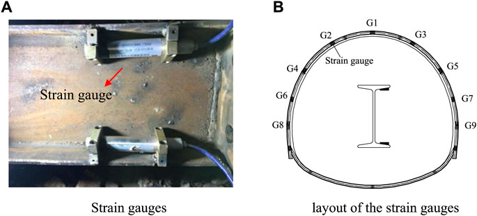
FIGURE 14. Test scheme of the internal stress of steel arches. (A) Strain gauges. (B) layout of the strain gauges.
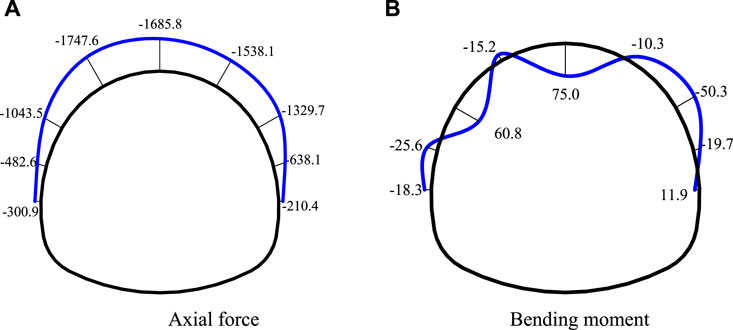
FIGURE 15. Testing results of the internal force. (A) Axial force. (B) Bending moment.
Through the analysis of on-site monitoring results, the failure mechanism of the Wanhe tunnel can be summarized as squeezing effect and loosening effect, which are explained as follows:
(1) The rapid growth of Wanhe tunnel deformation in the early first stage was caused by the squeezing effect. Due to tunnel excavation, the stress state of rock mass changes from a three-dimensional state to a two-dimensional state. Then the rock stress begins to redistribute with the release of deformation to reach a new equilibrium state. The field test results showed that the Wanhe tunnel was located in the broken granite stratum with low strength and high geostress. Thus tunnel excavation caused great disturbance to the surrounding rock, resulting in a sharp increase of the tangential stress around the tunnel section and a large amount of rock deformation squeezing the supporting structures. After 20 days, the tunnel deformation entered the slow growth stage, which means that most of the squeezing deformation had been released.
(2) The other growth trend of the vault settlement in the later stage was caused by the loosening effect. Figure 16 is the diagram of the convergence confinement method. GRC is the ground response curve, which represents the relationship between the rock pressure and the tunnel deformation. SCC is the support characteristic curve, which represents the relationship between the support force and the tunnel deformation. After tunnel excavation, the rock pressure gradually decreases with stress release and deformation development. The rock pressure at this stage is mainly the squeezing pressure. When the tangential stress around the tunnel section exceeds the yielding strength of the surrounding rock, plastic deformation and fracture propagation will develop in the rock mass, thus resulting in a loosened zone around the tunnel. The field test on site showed a significant loosened zone around the Wanhe tunnel, which created loosening pressure on the supporting structures and further worsened the tunnel deformation.
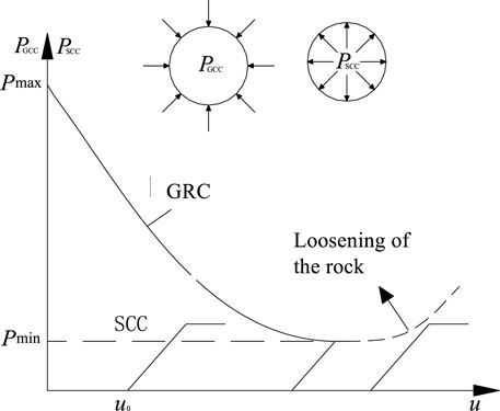
FIGURE 16. The convergence confinement method.
According to the on-site monitoring results, the deformation state of the tunnel in tectonic fracture zones under high in-situ stresses was considered to be a dynamic process, which was not usually instantaneous and showed an obvious space-time effect. Deformation is the most direct indicator to reflect the state of the surrounding rock. It has the characteristics of large growth rate and long duration in the early stage caused by the squeezing effect and showed another growth trend in the later stage due to the loosening effect.
Based on these characteristics, this paper proposed the dynamic control process method. This method is based on the combination principle of stress releasing and support resistance. It first allows the rock mass deformation to exert its bearing capacity. Then, it requires the reinforcement of rock and the strengthening of supports to prevent rock failure and control the deformation within the reserved range. Figure 17 is the flowchart of the dynamic control process method. It requires the control measures to be taken in process by identifying the evolution stages of deformation through on-site monitoring. Details are described as follow: 1) Firstly, predict the deformation grade and determine the deformation allowance based on the ratio of the uniaxial compressive strength to the maximum principal stress through on-site measurement. 2) Before the tunnel excavation, advanced supports are installed to prevent the tunnel face instability. 3) After excavation, the flexible primary supports including the shotcrete and the steel arches should be conducted in time to form the ring closure of the tunnel, which is the premise of subsequent construction safety. 4) In the rapid growth stage, it allows to release the deformation of the surrounding rock based on the stress releasing principle to fully utilize the original bearing capacity of the surrounding rock. 5) When the deformation rate decreases significantly and enters the slow growth stage, active control methods are used to reinforce the surrounding rock in time to improve the resistance. 6) If the deformation rate shows another growing trend in the later stage, based on the support resistance principle, the passive control methods are used to strengthen the supporting structures and restrain the rock deformation within the reserved range.
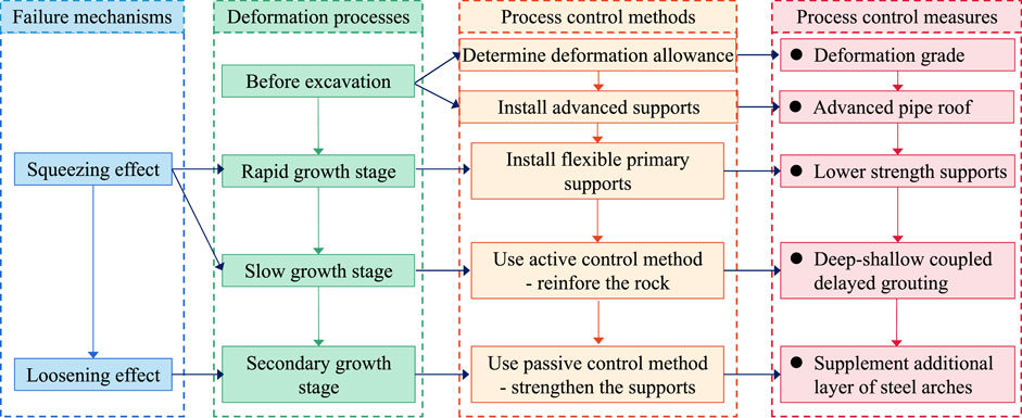
FIGURE 17. Dynamic process control method.
Predicting the potential squeezing intensity and the deformation grade is the premise of the squeezing tunnel construction, which can improve the applicability of the control measures. In this paper, the deformation grade of the Wanhe tunnel was determined according to the Code for Tunneling in Squeezing Rock in China [Q/CR9812-2019, (Code for Tunnelling in Squeezing Rocks, 2019)], which divides the squeezing potential into three grades with the index of rock strength-stress ratio as shown in Table 3. According to the field testing results on site, the ratio of the uniaxial compressive strength (Rc) to the maximum in-situ stress (σmax) is 0.12. Thus the deformation grade of the Wanhe tunnel can be determined as Grade Ⅲ, which means that the tunnel has great squeezing potential. Further, the Code [Q/CR9812-2019, (Code for Tunnelling in Squeezing Rocks, 2019)] gives the recommended values of deformation allowance for different deformation grades in Table 3. Considering the previous maximum deformation monitored on site, the proposed deformation allowance of the Wanhe tunnel was 500 mm in this study.
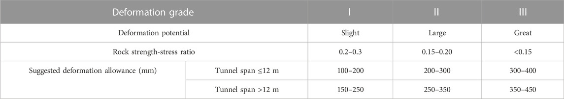
TABLE 3. Classification standard of deformation grade and suggested deformation allowance.
Due to weak rock mass with developed joints, collapses at the top of the tunnel face often occurred during excavation. To prevent the tunnel face instability, an advanced support scheme was proposed during the Wanhe tunnel construction. Steel tubes of 6 m in length, and 76 mm in diameter were used as the advanced pipe roofs, which were arranged above steel arches with 40 cm circumferential spacing and 3.6 m longitudinal spacing. The angle between the steel pipe and the longitudinal direction is about 1°–2°. There are grouting holes at the ends of the steel pipes. The grout in the advanced pipe roof was the cement paste, which can bond the steel tubes and rock mass to improve the effect of advanced support. After installing the advanced supports, the Wanhe tunnel was excavated through the three-step method and supported with the primary support in time. The primary support consisted of steel arches, shotcrete, and anchor bolts. The steel arches are made of shaped steel of I20b with 0.6 m spacing. Shotcrete with the strength of C25 and the thickness of 27 cm was used on site. Anchor bolts of 3.5 m in length and 25 mm in diameter are installed at intervals of 1.0 m. This is a flexible support system with deformation release ability.
Grouting is one kind of active control method to improve the bearing capacity of surrounding rock by bonding the broken rock mass with slurry. However, for deep buried tunnels in tectonic fracture zones, the fissures in the surrounding rock are compacted by high in-situ stresses in the early stage, which makes it difficult to inject the grout. Therefore, the delayed grouting method following the dynamic control principle is proposed in this paper. It firstly allows to release the deformation of the surrounding rock in the rapid growth stage to develop the fissures in the surrounding rock, thus improving the injectability of grout. The time when the tunnel deformation begins to enter the slow growth stage is suggested as the best grouting timing. Based on the monitoring results of real-time deformation on site, grouting was carried out when the deformation rate decreased significantly during the construction of the Wanhe tunnel.
The thickness of the grouted reinforcement layer depends on the thickness of the loosened ring. The loosened zone is the area where the fissures in the surrounding rock are highly developed after excavation. The injectability of this area is relatively large under high in situ stress. The purpose of grouting is to repair and consolidate the surrounding rock in the loosened ring. In Figure 12, the field test on site showed a significant loosened zone with an average depth of 9.6 m. In order to ensure the range of reinforcement, steel tubes with a length of 6.0 m were selected for grouting. This paper proposed the deep-shallow coupled grouting scheme, the process of which is described as follows:
(1) Firstly, deep and shallow grouting holes were drilled in the surrounding rock with the layout shown in Figure 18. They were arranged in the shape of plum blossoms with distances of 3.0 m (for deep grouting holes) and 1.2 m (for shallow grouting holes) respectively. Steel tubes of 6.0 m in length and 42 mm in diameter were used for the grouting of deep holes, while the tubes with 2.0 m in length and 42 mm in diameter were used for the shallow holes.
(2) When the monitored deformation began to decrease, the loosened and broken rock mass in shallow was grouted first through the steel tubes in the shallow holes. Grouting started from the side wall of the middle bench, then to the spandrels of the upper bench, and finally to the tunnel vault. The grout was the mixture of the ordinary portland cement slurry (with a cement strength grade of 42.5 and a water-cement ratio of 0.8) and the water glass (with a mixing amount of 3%). The grouting pressure was controlled within a lower range from 0.5 to 1.0 MPa to ensure the safety of the primary supports.
(3) When the shallow grouting layer was solidified, the rock mass in deep was grouted through the steel tubes in the deep holes. By increasing the grouting pressure and using high-permeability materials, the slurry can be diffused to the deep, thereby improving the grouting range. During high-pressure grouting, the finished shallow grouting layer can stop the slurry and prevent slurry leakage. Otherwise, the high grouting pressure would damage the soft rock in shallow and further crush the primary supports. The grouting order was the same as that of the shallow holes. The grout material with high permeability and high strength contains the ordinary portland cement slurry (with a cement strength grade of 52.5 and a water-cement ratio of 0.6) and the water reducer (with the mixing amount of 0.7%). The grouting pressure was controlled within the range from 2.0 to 3.0 MPa.
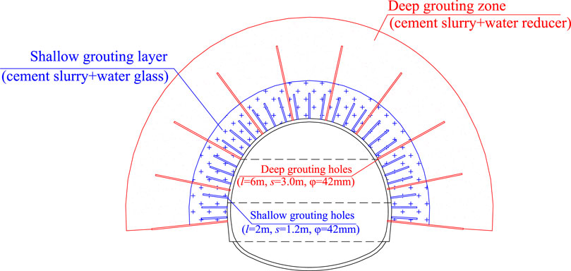
FIGURE 18. Deep-shallow coupled grouting scheme.
After grouting, some sections of the Wanhe tunnel continued to deform and even showed another growing trend in the later stage, which seemed difficult to converge within the deformation allowance. Thus, to restrain the tunnel deformation, the passive control method was carried out by supplementing another layer of steel arch. The second layer of steel arch is made of shaped steel of I22b with a spacing of 0.6 m, which were installed on the inverted arches reaching the required strength. Two adjacent arches were connected with the steel bars, which have a diameter of 22 mm and a circumferential spacing of 0.6 m. In addition, a total of six lock-feet anchor pipes with a diameter of 42 mm and a length of 4.5 m were installed at the arch foot of each ring. The end of the lock-feet anchor pipes has grout vent holes, which allows for consolidating the anchor pipes and the nearby rock by grouting so that the arch feet could not sink and slip. In order to transfer the deformation load from the first layer of the primary support to the second layer of steel arches, wooden blocks were used to wedge them.
According to the dynamic process control method proposed in this paper, the large deformation of the Wanhe tunnel (from DK32+725 to DK32+100) was generally controlled by the basic comprehensive measures containing advanced supports, flexible primary supports, and delayed grouting. Further, the deformation of some special sections (sections at DK32+338∼+171, DK32+400∼ DK32+340, and DK32+615∼ DK32+415) still kept increasing without a stable trend after grouting reinforcement. Therefore, the control measure of the double steel arch was supplemented in these sections.
Figure 19 shows the dynamic process control measures carried out on site. As mentioned, monitoring is an efficient approach to evaluate the effect that countermeasures play on controlling tunnel deformation. By real-time measuring during the following construction, the evolution curves of vault settlement with time under the modified controlling measures are shown in Figure 20. The control effect can be evaluated as follows:
(1) Figure 20A shows that the vault settlement of the DK32+155 section had a rapid growth stage lasting 28 days, and then entered a slow growth stage. The rock grouting was carried out on the 29th day. After that, the vault settlement gradually converged and reached stability on the 50th day. The cumulative amount of vault settlement was 375.2 mm, which was less than the deformation allowance. This indicated that the delayed grouting method effectively reinforced the loosened rock mass and well controlled the tunnel deformation.
(2) Since the deformation of the DK32+230 section had no stable trend after grouting, the second layer of steel arch was implemented when the vault settlement reached 450 mm. Figure 20B shows that the deformation rate was greatly reduced after installing the second layer of steel arches. After 29 April 2019, the vault settlement became stable within the deformation allowance and did not increase again. This indicated that the second layer of steel arches had an obvious effect on restraining the development of the rock loosened zone and stabilizing the tunnel deformation.
(3) In addition, the tunnel cracking and steel twisting were greatly reduced in the Wanhe tunnel. These all indicated the rationality and applicability of the dynamic process control measures for large deformation tunnels in tectonic fracture zones under high in-situ stresses. Finally, the Wanhe tunnel completed in March 2020.
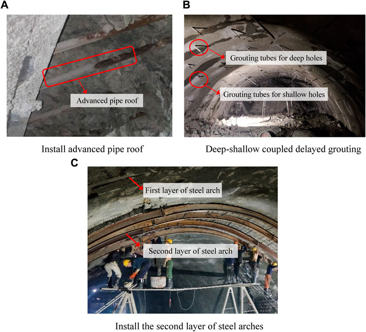
FIGURE 19. Dynamic process control measures on site. (A) Install advanced pipe roof. (B) Deep-shallow coupled delayed grouting. (C) Install the second layer of steel arches.

FIGURE 20. Deformation evolution after dynamic process control measures. (A) Deformation evolution of DK32+155 section. (B) Deformation evolution of DK32+230 section.
Based on the Wanhe tunnel of the China-Laos railway, this study discusses the failure mechanisms and proposed the dynamic process control measures for a deep buried tunnels in tectonic fracture zones under high in-situ stresses. The major conclusions of this study are as follows:
(1) In situ stress test through hydraulic fracturing method found out that the tunnel was located in a high geostress field and would be easily squeezed and deformed. The ultrasonic wave testing for the surrounding rock showed a significant loosened zone around the tunnel, which would further worsen the tunnel deformation. Deformation evolution had the characteristic of rapid growth in the early stage caused by the squeezing effect. In the later stage, the vault settlement had another growth trend due to the loosening effect of the surrounding rock. The squeezing and loosening effects lead to stresses in the vault and shoulder exceeding the yield strength of the steel arches.
(2) Aiming at the failure mechanism, this study proposed the dynamic process control method based on the combination principle of stress releasing and support resistance. It first allows to release the deformation of the surrounding rock in the rapid growth stage and then requires to control the deformation within the reserved range by reinforcing the surrounding rock and strengthening support structures in the later stage. Further, the dynamic process control measures were proposed in this paper including the advanced and primary supports, the deep-shallow coupled delayed grouting method, and the double steel arches method.
(3) Based on the in situ monitoring results, it was found that the vault settlement and horizontal convergence were well released and controlled with the dynamic process control measures and finally reached stability within the deformation allowance. In addition, tunnel cracking and steel twisting were greatly reduced. Finally, the construction of the Wanhe tunnel was well finished. This study suggests that the proposed measures can guarantee the construction safety of deep buried tunnels in tectonic fracture zones under high in-situ stresses.
The original contributions presented in the study are included in the article/Supplementary material, further inquiries can be directed to the corresponding author.
KZ: Writing–original draft, Writing–review and editing. CS: Writing–original draft, Writing–review and editing. QZ: Data curation, Investigation, Writing–original draft. ML: Formal Analysis, Methodology, Writing–review and editing. CJ: Conceptualization, Writing–review and editing. YL: Data curation, Investigation, Methodology, Writing–review and editing.
The authors thank the Kunming Group Co., Ltd. and the 12th Bureau Group Co., Ltd. of China Railway for cooperation in the field tests and data collection for this study. The authors acknowledge the financial support provided by the Science and Technology Research and Development Program Project of China railway group limited (Key Project, No. 2021-Key-09).
Authors KZ and CS were employed by China Railway Group Limited. Author QZ was employed by China Railway Kunming Group Co., Ltd.
The authors declare that this study received funding from the Science and Technology Research and Development Program Project of China railway group limited (Key Project, No. 2021-Key-09). The funder was involved in the study design, cooperation for field investigation and evaluation of research results.
The remaining authors declare that the research was conducted in the absence of any commercial or financial relationships that could be construed as a potential conflict of interest.
All claims expressed in this article are solely those of the authors and do not necessarily represent those of their affiliated organizations, or those of the publisher, the editors and the reviewers. Any product that may be evaluated in this article, or claim that may be made by its manufacturer, is not guaranteed or endorsed by the publisher.
Aksoy, C. O., Ogul, K., Topal, I., Ozer, S. C., Ozacar, V., and Posluk, E. (2012). Numerical modeling of non-deformable support in swelling and squeezing rock. Int. J. Rock Mech. Min. Sci. 52, 61–70. doi:10.1016/j.ijrmms.2012.02.008
Ayaydin, N., and Leitner, A. (2009). Tauern tunnel first and second tubes from the consultant's viewpoint. Geomech. Tunn. 2 (1), 14–23. doi:10.1002/geot.200900001
Barla, G., Bonini, M., and Semeraro, M. (2011). Analysis of the behaviour of a yield-control support system in squeezing rock. Tunn. Undergr. Space Technol. 26 (1), 146–154. doi:10.1016/j.tust.2010.08.001
Bonini, M., and Barla, G. (2012). The Saint Martin La porte access adit (Lyon–Turin Base tunnel) revisited. Tunn. Undergr. Space Technol. 30, 38–54. doi:10.1016/j.tust.2012.02.004
Cantieni, L., and Anagnostou, G. (2009). The interaction between yielding supports and squeezing ground. Tunn. Undergr. Space Technol. 24 (3), 309–322. doi:10.1016/j.tust.2008.10.001
Cao, C. Y., Shi, C. H., Lei, M. F., Yang, W. C., and Liu, J. W. (2018). Squeezing failure of tunnels: a case study. Tunn. Undergr. Space Technol. 77, 188–203. doi:10.1016/j.tust.2018.04.007
Chen, Y. F., Zheng, H. K., Wang, M., Hong, J. M., and Zhou, C. B. (2015). Excavation-induced relaxation effects and hydraulic conductivity variations in the surrounding rocks of a large-scale underground powerhouse cavern system. Tunn. Undergr. Space Technol. 49, 253–267. doi:10.1016/j.tust.2015.05.007
Chen, Z. Q., He, C., Xu, G. W., Ma, G. Y., and Yang, W. B. (2019). Supporting mechanism and mechanical behavior of a double primary support method for tunnels in broken phyllite under high geo-stress: a case study. B. Eng. Geol. Environ. 78 (7), 5253–5267. doi:10.1007/s10064-019-01479-1
Code for design on railway tunnel (TB10003—2016) (2017). The professional standards compilation group of peoples Republic of China. Beijing: China Railway Publishing House. (in Chinese).
Code for Tunnelling in Squeezing Rocks (Q/CR9812-2019) (2019). Code for tunnelling in squeezing rocks (Q/CR9812-2019). Beijing: China Railway Publishing House. (in Chinese).
Deng, H. S., Fu, H. L., Shi, Y., Zhao, Y. Y., and Hou, W. Z. (2022). Countermeasures against large deformation of deep-buried soft rock tunnels in areas with high geostress: a case study. Tunn. Undergr. Space Technol. 119, 104238. doi:10.1016/j.tust.2021.104238
Franz, W., and Harald, L. (2009). The Tauern tunnel first and second tubes from the contractor's viewpoint. Geomech. Tunn. 2 (1), 24–32. doi:10.1002/geot.200900002
Guan, K., Zhu, W., Liu, X., Wei, J., and Niu, L. (2020). Re-profiling of a squeezing tunnel considering the post-peak behavior of rock mass. Int. J. Rock. Mech. Min. Sci. 125, 104153. doi:10.1016/j.ijrmms.2019.104153
Horyl, P., Snuparek, R., and Hlavackova, M. (2013). Loading capacity of yielding connections used in steel arch roadway supports. Seventh Int. Symposium Ground Support in Min. Undergr. Constr., 461–470. doi:10.36487/ACG_rep/1304_31_Horyl
Iasiello, C., Guerra Torralbo, J. C., and Torrero Fernández, C. (2021). Large deformations in deep tunnels excavated in weak rocks: study on Y-Basque high-speed railway tunnels in northern Spain. Undergr. Space 6 (6), 636–649. doi:10.1016/j.undsp.2021.02.001
International society for rock mechanics (1987). Suggested methods for rock stress determination. Int. J. Rock Mech. Min. Sci. 24 (1), 55–73. doi:10.1016/0148-9062(87)91232-0
Jeong, S. S., Han, Y. C., Kim, Y. M., and Kim, D. H. (2014). Evaluation of the NATM tunnel load on concrete lining using the ground lining interaction model. KSCE J. Civ. Eng. 18 (2), 672–682. doi:10.1007/s12205-014-0597-9
John, M. (1980). Arleberg expressway tunnel - Part 4. Construction of the Arlberg expressway tunnel tube. Int. J. Rock Mech. Min. Sci. 17 (6), A114. doi:10.1016/0148-9062(80)90638-5
Kang, H., Jiang, P., Wu, Y., and Gao, F. (2021). A combined “ground support-rock modification-destressing” strategy for 1000-m deep roadways in extreme squeezing ground condition. Int. J. Rock Mech. Min. Sci. 142, 104746. doi:10.1016/j.ijrmms.2021.104746
Kimura, F., Okabayashi, N., and Kawamoto, T. (1987). Tunnelling through squeezing rock in two large fault zones of the Enasan Tunnel II. Rock Mech. Rock Eng. 20 (3), 151–166. doi:10.1007/BF01020366
Li, C. C., Stjern, G., and Myrvang, A. (2014). A review on the performance of conventional and energy-absorbing rockbolts. J. Rock Mech. Geotech. 6 (4), 315–327. doi:10.1016/j.jrmge.2013.12.008
Li, P. F., Tian, S. M., Zhao, Y., Zhu, Y., and Wang, S. (2013). In-situ monitoring study of mechanical characteristics of primary lining in weak rock tunnel with high grostress. Chin. J. Rock Mech. Eng. 32 (S2), 3509–3519. doi:10.3969/j.issn.1000-6915.2013.z2.066
Lin, Y. X., Lai, Z. S., Ma, J. J., Huang, L. C., and Lei, M. F. (2023). A FDEM approach to study mechanical and fracturing responses of geo-materials with high inclusion contents using a novel reconstruction strategy. Eng. Fract. Mech. 282, 109171. doi:10.1016/j.engfracmech.2023.109171
Ma, J. J., Zhao, J. X., Lin, Y. X., Liang, J. G., Chen, J. J., Chen, W. X., et al. (2023). Study on tamped spherical detonation-induced dynamic responses of rock and PMMA through mini-chemical explosion tests and a four-dimensional lattice spring model. Rock Mech. Rock Eng. 56 (10), 7357–7375. doi:10.1007/s00603-023-03426-9
Mezger, F., Anagnostou, G., and Ziegler, H. J. (2013). The excavation-induced convergences in the sedrun section of the gotthard Base tunnel. Tunn. Undergr. Space Technol. 38, 447–463. doi:10.1016/j.tust.2013.07.016
Mezger, F., Ramoni, M., Anagnostou, G., Dimitrakopoulos, A., and Meystre, N. (2017). Evaluation of higher capacity segmental lining systems when tunnelling in squeezing rock. Tunn. Undergr. Space Technol. 65, 200–214. doi:10.1016/j.tust.2017.02.012
Milnes, A. G. (1973). Structural reinterpretation of the classic Simplon tunnel section of the central alps. GSA Bull. 84 (1), 269–274. doi:10.1130/0016-7606(1973)84<269:SROTCS>2.0.CO;2
Ortlepp, W. D., and Stacey, T. R. (1998). Performance of tunnel support under large deformation static and dynamic loading. Tunn. Undergr. Space Technol. 13 (1), 15–21. doi:10.1016/S0886-7798(98)00022-4
Qiao, Y. F., Tang, J., Liu, G. Z., and He, M. C. (2022). Longitudinal mechanical response of tunnels under active normal faulting. Undergr. Space 7 (4), 662–679. doi:10.1016/j.undsp.2021.12.002
Radoncić, N., Schubert, W., and Moritz, B. (2009). Ductile support design. Geomech. Tunn. 2 (5), 561–577. doi:10.1002/geot.200900054
Rodríguez, R., and Díaz-Aguado, M. B. (2013). Deduction and use of an analytical expression for the characteristic curve of a support based on yielding steel ribs. Tunn. Undergr. Space Technol. 33, 159–170. doi:10.1016/j.tust.2012.07.006
Rowedder, S. (2020). Railroading land-linked Laos: China's regional profits, Laos' domestic costs? Eurasian Geogr. Econ. 61 (2), 152–161. doi:10.1080/15387216.2019.1704813
Schubert, W., Brunnegger, S., Staudacher, R., and Wenger, J. (2018). Further development of yielding elements and connecting elements for shotcrete. Geomech. Tunn. 11 (5), 575–581. doi:10.1002/geot.201800038
Sun, X., Zhao, C., Tao, Z., Kang, H., and He, M. (2021). Failure mechanism and control technology of large deformation for Muzhailing Tunnel in stratified rock masses. B. Eng. Geol. Environ. 80 (6), 4731–4750. doi:10.1007/s10064-021-02222-5
Tan, X., Chen, W., Liu, H., Chan, A. H. C., Tian, H., Meng, X., et al. (2017). A combined supporting system based on foamed concrete and U-shaped steel for underground coal mine roadways undergoing large deformations. Tunn. Undergr. Space Technol. 68, 196–210. doi:10.1016/j.tust.2017.05.023
Tan, Z. S., Li, S. T., Yang, Y., and Wang, J. J. (2022). Large deformation characteristics and controlling measures of steeply inclined and layered soft rock of tunnels in plate suture zones. Eng. Fail. Anal. 131, 105831. doi:10.1016/j.engfailanal.2021.105831
Tian, H. M., Chen, W. Z., Tan, X. J., Yang, D. S., Wu, G. J., and Yu, J. X. (2018). Numerical investigation of the influence of the yield stress of the yielding element on the behaviour of the shotcrete liner for yielding support. Tunn. Undergr. Space Technol. 73, 179–186. doi:10.1016/j.tust.2017.12.019
Tian, H. M., Chen, W. Z., Yang, D. S., Wu, G. J., and Tan, X. J. (2016). Numerical analysis on the interaction of shotcrete liner with rock for yielding supports. Tunn. Undergr. Space Technol. 54, 20–28. doi:10.1016/j.tust.2016.01.025
Tian, Y., Chen, W. Z., Tian, H. M., Tan, X. J., Li, Z., and Lei, J. (2021). Parameter design of yielding layers for squeezing tunnels. Tunn. Undergr. Space Technol. 108, 103694. doi:10.1016/j.tust.2020.103694
Ulusay, R. (2015). The ISRM suggested methods for rock characterization. Testing and monitoring 2007-2014. Springer International Publishing. doi:10.1007/978-3-319-07713-0
VandeKraats, J. D., and Watson, S. (1996). Direct laboratory tensile testing of select yielding rock bolt systems. Carlsbad,NM (United States): Westinghouse Electric Corp. doi:10.2172/367133
Vrakas, A., and Anagnostou, G. (2016). Ground response to tunnel Re-profiling under heavily squeezing conditions. Rock Mech. Rock Eng. 49 (7), 2753–2762. doi:10.1007/s00603-016-0931-2
Wan, F., Tan, Z. S., and Ma, D. (2014). Optimizing design of support structure for Guanjiao Tunnel in fault-rupture zone F2-1. Chin. J. Rock. Mech. Eng. 33 (3), 531–538. doi:10.13722/j.cnki.jrme.2014.03.011
Wang, H., Chen, W. Z., Tan, X. J., Tian, H. M., and Cao, J. J. (2012). Development of a new type of foam concrete and its application on stability analysis of large-span soft rock tunnel. J. Cent. South. Univ. 19 (11), 3305–3310. doi:10.1007/s11771-012-1408-4
Wang, Q., Jiang, B., Pan, R., Li, S. C., He, M. C., Sun, H. B., et al. (2018). Failure mechanism of surrounding rock with high stress and confined concrete support system. Int. J. Rock Mech. Min. Sci. 102, 89–100. doi:10.1016/j.ijrmms.2018.01.020
Wang, Q., Pan, R., Jiang, B., Li, S. C., He, M. C., Sun, H. B., et al. (2017). Study on failure mechanism of roadway with soft rock in deep coal mine and confined concrete support system. Eng. Fail Anal. 81, 155–177. doi:10.1016/j.engfailanal.2017.08.003
Wang, Y. Q., Li, J. Q., Wang, Z. F., and Chang, H. T. (2022). Structural failures and geohazards caused by mountain tunnel construction in fault zone and its treatment measures: a case study in Shaanxi. Eng. Fail. Anal. 138, 106386. doi:10.1016/j.engfailanal.2022.106386
Wu, F. Q., Miao, J. L., Bao, H., and Wu, J. (2015). Large deformation of tunnel in slate-schistose rock: a case study on muzhailing tunnel, lan-yu railway, China. China. Eng. Geol. Soc. territ. 6, 17–23. doi:10.1007/978-3-319-09060-3_3
Wu, G., Chen, W., Jia, S., Tan, X., Zheng, P., Tian, H., et al. (2020). Deformation characteristics of a roadway in steeply inclined formations and its improved support. Int. J. Rock. Mech. Min. Sci. 130, 104324. doi:10.1016/j.ijrmms.2020.104324
Wu, G., Chen, W., Tian, H., Jia, S., Yang, J., and Tan, X. (2018). Numerical evaluation of a yielding tunnel lining support system used in limiting large deformation in squeezing rock. Environ. Earth. Sci. 77 (12), 439. doi:10.1007/s12665-018-7614-0
Wu, K., Shao, Z., Qin, S., Wei, W., and Chu, Z. (2021). A critical review on the performance of yielding supports in squeezing tunnels. Tunn. Undergr. Space Technol. 115, 103815. doi:10.1016/j.tust.2021.103815
Xu, D. P., Zhou, Y. Y., Qiu, S. L., Jiang, Q., and Wang, B. (2018). Elastic modulus deterioration index to identify the loosened zone around underground openings. Tunn. Undergr. Space Technol. 82, 20–29. doi:10.1016/j.tust.2018.07.032
Yang, J. S., Yan, L., Deng, S. J., and Li, G. L. (2006). Interactions of four tunnels driven in squeezing fault zone of Wushaoling Tunnel. Tunn. Undergr. Space Technol. 21 (3-4), 359. doi:10.1016/j.tust.2005.12.176
Zhang, C., Tan, X., Tian, H., and Chen, W. (2022). Lateral compression and energy absorption of foamed concrete-filled polyethylene circular pipe as yielding layer for high geo-stress soft rock tunnels. Int. J. Min. Sci. Technol. 32 (5), 1087–1096. doi:10.1016/j.ijmst.2022.08.011
Zhang, D. L., Sun, Z. Y., and Fang, Q. (2022). Scientific problems and research proposals for Sichuan–Tibet railway tunnel construction. Undergr. Space. 7 (3), 419–439. doi:10.1016/j.undsp.2021.10.002
Zhang, Q., Li, Y.-J., Wang, H.-Y., Yin, Q., and Wang, X.-F. (2022). Re-profiling response of heavily squeezed tunnels via ground reaction curves. Tunn. Undergr. Space Technol. 123, 104411. doi:10.1016/j.tust.2022.104411
Zhang, W. Q., Wang, Q. L., Li, J. W., and Gao, P. (2010). Case study on large deformation control technology of Muzhailing tunnel. Tunn. Constr. 30 (2), 157–161. CNKI:SUN:JSSD.0. 2010-02-013.
Keywords: high in-situ stresses, tectonic fracture zone, squeezing effect, loosening effect, dynamic process control measures
Citation: Zheng K, Shi C, Zhao Q, Lei M, Jia C and Lou Y (2023) Failure mechanisms and dynamic process control measures of deep buried tunnels in tectonic fracture zones under high in-situ stresses—a case study in Southwestern China. Front. Earth Sci. 11:1289251. doi: 10.3389/feart.2023.1289251
Received: 05 September 2023; Accepted: 21 November 2023;
Published: 29 December 2023.
Edited by:
Pengjiao Jia, Soochow University, ChinaReviewed by:
Jianjun Ma, Sun Yat-Sen University, ChinaCopyright © 2023 Zheng, Shi, Zhao, Lei, Jia and Lou. This is an open-access article distributed under the terms of the Creative Commons Attribution License (CC BY). The use, distribution or reproduction in other forums is permitted, provided the original author(s) and the copyright owner(s) are credited and that the original publication in this journal is cited, in accordance with accepted academic practice. No use, distribution or reproduction is permitted which does not comply with these terms.
*Correspondence: Chenghua Shi, Y3N1c2NoQDE2My5jb20=
Disclaimer: All claims expressed in this article are solely those of the authors and do not necessarily represent those of their affiliated organizations, or those of the publisher, the editors and the reviewers. Any product that may be evaluated in this article or claim that may be made by its manufacturer is not guaranteed or endorsed by the publisher.
Research integrity at Frontiers
Learn more about the work of our research integrity team to safeguard the quality of each article we publish.