 Yong Mei
- Fire Prevention and Control Research Institute, China Coal Technology & Engineering Group Chongqing Research Institute, Chongqing, China
Fires formed by the high gas protrusion in coal mines are difficult and risky to extinguish during the mine closure process due to the mine’s large closed range and underground gas stock. To achieve efficient and safe unsealing, reduce the risk of re-ignition and gas explosion, and accurately determine the fire extinguishing effect, a dual-drive rapid fire extinguishing technology is proposed. This technology involves ground precise positioning of drilling holes, rapid and large flow of liquid nitrogen injection, and curtain grouting to block fires in ultra-large high-gas mines. The practical results demonstrate that the implementation of surface injection of liquid nitrogen for fire extinguishing and cooling, and plugging effectively reduces the concentration of CO in the underground space from 230 PPm to 0 PPm, and decreases the CH4 concentration content from 90% to less than 0.75%. The fire extinguishing and cooling effect is fast and significant. A technical scheme for unsealing the fire area of the whole mine is formulated on a large scale based on the state of pumping and releasing pressure in the closed space of the mine. This scheme has important guiding significance for safety rescue and rescue operations after serious fire accidents occur in similar high-gas prominent mines.
1 Introduction
Mine fires are a significant hazard for coal mining operations, posing a direct threat to the safety and wellbeing of production personnel while also causing major losses of national resources and property (Hu et al., 2015). In addition, mine fires generate toxic and harmful gases and inflict severe damage on the ecological environment, making them a serious environmental concern. Furthermore, mine fires can lead to gas explosions and other catastrophic disasters, compounding the damage and loss caused by the initial fire (Shekharsharan, 2009; Cloves, 2014; Yang et al., 2022). To extinguish a mine fire, the complex combustion state and environmental conditions pose significant challenges (Shen and Guo, 2009). In addition, the limitations of gas analysis time, equipment, and technical conditions further complicate the process (Sun et al., 2011; Xue et al., 2012).
Liquid nitrogen is an effective and promising extinguishing agent. When used to put out fires, it produces an inert gas as vapor (Shi et al., 2015; Hiroyuki et al., 2016). This gas is non-flammable, stable, and non-corrosive. Liquid nitrogen remains in a liquid state at low temperatures and absorbs a significant amount of heat during the process of changing from liquid to gas. As a result, it lowers the temperature in the mining area rapidly, which can delay or even prevent the spontaneous combustion of coal in the mining area (Mohalik et al., 2005). The gasification of 1 cubic meter of liquid nitrogen at normal temperature can produce approximately 700 cubic meters of nitrogen gas, which expands the volume by about 700 times. This process fills the effective space of nitrogen in a short amount of time, rapidly reducing the oxygen concentration in the goaf and cutting off the oxygen supply channel for the spontaneous combustion of remaining coal. This technique is beneficial not only for preventing the spontaneous combustion of leftover coal, but also for reducing air leakage in the goaf. In 1949, liquid nitrogen fire extinguishing technology was first applied at the Doubrave coal mine in the Czech Republic and successfully stopped the spread of coal mine fires (Vaughan-Thomas, 1964). Since then, this technology has been utilized at various mines worldwide, including Fernhilly and Fryston mines in the United Kingdom, Osterfeld, Schlagel, and Eisen mines in Germany, Rozelay mine in France, and Springfield mine in South Africa (Wastell and Walker, 1983; Bacharach et al., 1986; Fauconnier and Meyer, 1986; Banerjee, 1987; Ray and Singh, 2007). Liquid nitrogen is commonly used in coal mine fire extinguishing technology as vaporized nitrogen, but its full potential has not been realized (Xue et al., 2008). However, when liquid nitrogen is directly transmitted through pipelines, it can lead to pipeline blockages and pose safety hazards to the system. To mitigate these risks, accurate detection and location technology for underground fires in coal mines is necessary. Xue et al. conducted two underground coal fire field trials in Australia using 222Rn technology, while some domestic coal mining enterprises have started to use directional drilling technology for accurate detection and treatment of hidden water hazards at the coal seam floor (Li, 2014; Yan, 2016; Zhao et al., 2016). This technology allows for precise positioning at the surface to target fire sources for rapid suppression operations. In the process of blocking, the seepage property is also very important to the fire extinguishing (Ma et al., 2022a). The seepage mechanism of rock mass is the key of plugging effect (Ma et al., 2022b). Dan Ma proposed a new concept of pore tortuosity index of broken rock mass. This index can reflect the spatial distribution and particle size distribution characteristics of broken rock particles, and is not affected by water flow behavior (Geng et al., 2023; Ma et al., 2023).
This research proposes a novel “dual-drive” closed fire extinguishing technology for the efficient suppression and cooling of super large fires in mines, as well as for curtain grouting sealing. This technology combines the methods of ground precise positioning of drilling holes and rapid and large flow liquid nitrogen injection with curtain grouting sealing, to achieve rapid fire suppression and cooling, and fire source isolation through curtain grouting sealing. The “dual-drive” rapid fire extinguishing method not only enhances the efficiency of fire extinguishing, but also minimizes the risk of fire to mine facilities and personnel, providing an efficient and safe technical means of mine fire prevention and control. This technology is a crucial guideline for the safe and rapid extinguishing of fires in similar mines with high gas prominence.
2 General
2.1 Overview of the mine and face
Yanjing No. 1 Coal Mine is located in Hechuan District, Chongqing, China. It was built in December 2005 and put into operation in January of the following year. The coal seam K2 mined by the 10,201 coal mining face is a spontaneous combustion coal seam. Working face roadway side encounter reverse fault, coal seam superposition thickness of 9 m, in the direction of the exposed fault length of 20 m, then advance 139 m. CO gas appeared in the upper corner during the propulsion process, and measures such as injecting lime water, inhibitor and liquid nitrogen 50 tons were adopted to reduce the hidden danger.
2.2 Overview of fire accidents
Coal spontaneous combustion fire is a common phenomenon that occurs due to various factors such as the slow advance speed of the working face, loose and broken coal, and self-heating of the top coal. The ignition can happen when low-ignition point materials such as bamboo and wood cribs are used for the thickening of coal seam burn. Coal mine accident data indicate that any fuel can become the fuel of fire due to the underground airflow through the route (Mykola et al., 2019). The CO content of the mine return air shaft is an important indicator of the potential for a spontaneous combustion fire, and it can reach high levels (Sun and Yin, 2006; Xu et al., 2014; Rakesh et al., 2018; Dudley et al., 2019). For instance, the total air volume of the air shaft is 11,500 m3/min, and the maximum CO content is 180 × 10−6 m3/min, as illustrated in Figure 1. When a fire occurs, prompt action such as watering measures and timely evacuation can be effective in mitigating the damage.

FIGURE 1. CO monitoring data chart of mine return air shaft.
3 Wellbore closure disaster relief analysis
3.1 Wellbore closure disaster relief process
Following the accident, the mine was closed to deal with the disaster. During the process of sealing the mine shafts, several critical steps were taken, including sealing the man-vehicle and main inclined shafts, auxiliary inclined shafts, and return air inclined shafts. The sealing work was carried out sequentially, starting with the man-vehicle inclined shaft, followed by the main slope and masonry pouring concrete sealing. These measures helped to contain the disaster and prevent further harm to the mine workers and the surrounding environment. The successful sealing of the mine shafts also created a controlled environment that facilitated subsequent rescue and recovery operations.
Following the ‘Coal Mine Safety Regulations’ (2022 Edition) (Yin, 2017) fire zone closure requirements, first, close the side branch, and then close the main wind path. Before closing the main air path. To close the main air path, a gradual reduction of ventilation air volume is carried out by reducing the section of the inlet and return airway, and utilizing fan frequency conversion. After the main fan stops ventilation, the air inlet is sealed. After a certain period, stability is achieved, and the gas drainage pump is closed, followed by disconnecting of the drainage pipeline. Figures 2A–D illustrates the closed wall profile, closed wall, and reserved pipeline diagram of the main inclined shaft and the man-vehicle inclined shaft.
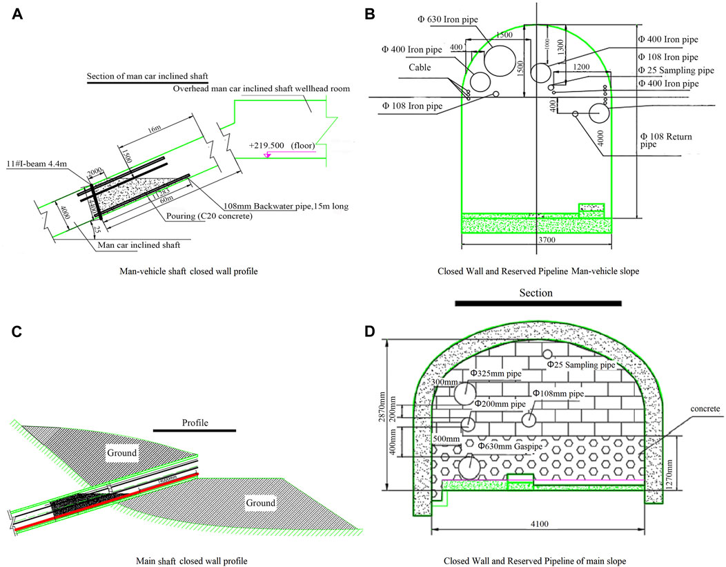
FIGURE 2. The closed wall profile, closed wall and reserved pipeline diagram of the main inclined shaft and the man-vehicle inclined shaft.
The closed wall and reserved pipeline section of the auxiliary inclined shaft and the return air shaft can be observed in Figures 3A, B. During the closure of the auxiliary inclined shaft and return air inclined shaft, the ventilation section frame and door are initially reserved, followed by the construction of a surrounding sandbag wall. The pipeline is then reserved for pouring concrete, which is ultimately poured by masonry.
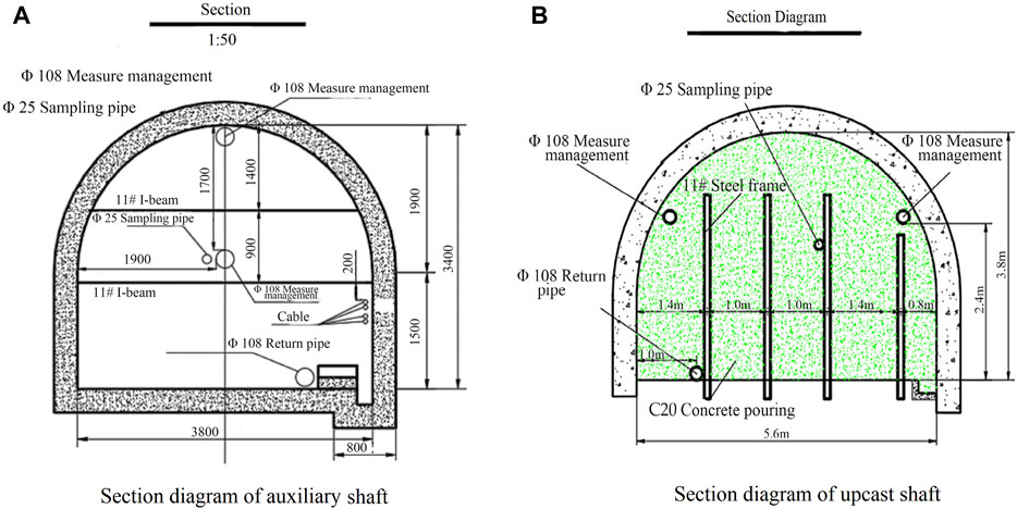
FIGURE 3. The closed wall and reserved pipeline section diagram of auxiliary inclined shaft and upcast shaft.
To ensure maximum safety during the disaster relief process, a closed wall with a thickness of 4 m at the bottom and 2 m at the top is adopted for the main inclined shaft, auxiliary inclined shaft, pedestrian inclined shaft, and return air inclined shaft. Additionally, sampling pipelines are reserved to facilitate post-accident analysis and further enhance safety measures.
3.2 Investigation of the effect of wellbore closure disaster relief
After a month of gas emission, the concentration of CH4 increased, and the oxygen concentration decreased to less than 5%. The changing trend of sampling and analysis data of closed wall in the return air shaft, auxiliary inclined shaft, main inclined shaft and man-vehicle inclined shaft was consistent, and the concentration of O2 and CO continued to decrease (see Figures 4A,B). CH4 gushed out of the mine, O2 decreased, and the CO2 fluctuation of combustion products increased; after nitrogen injection, CO2 of combustion gas products showed a continuous downward trend. As can be seen from Figures 4B,C, return air shaft closed detection pipeline sampling chromatography analysis, CO concentration from a maximum of more than 3000 PPm continued to fall below 100 PPm, CO2 concentration to maintain a stable trend of fluctuations, the development of fire has been effectively controlled.
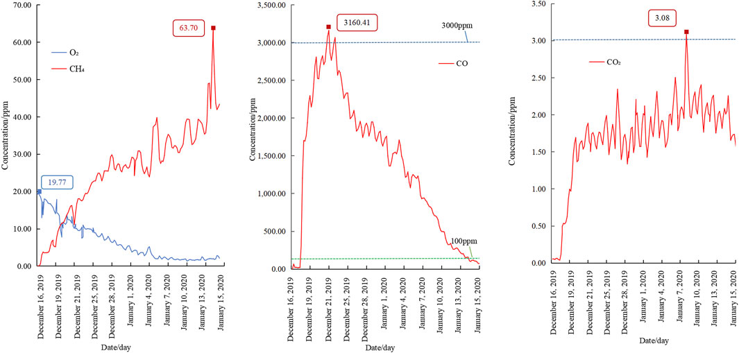
FIGURE 4. The concentration curves of O2, CH4, CO and CO2 in the return air shaft.
The complete closure of the mine has successfully prevented the expansion of damage and secondary accidents during the underground rescue operation of the protruding mine. However, it has also presented challenges for extinguishing the fire and reopening the mine.
4 Ground precise positioning drilling hole injection liquid nitrogen fire extinguishing analysis
4.1 Mechanism of liquid nitrogen injection for fire prevention
To prevent and extinguish fires using nitrogen injection, non-combustible nitrogen is injected into spaces that may cause coal spontaneous combustion or that have already caught fire. This reduces the oxygen content in the space and stops the combustion of combustibles, thus preventing and extinguishing the fire. The mechanism of nitrogen fire prevention and extinguishing is mainly based on oxidation (Bobo and Fubao, 2014), spontaneous combustion, and combustion of combustibles in coal, which can create an inert and flame-retardant effect (Zhao and Wang, 2007; Dong et al., 2011; Lin et al., 2022), suppressing explosions. Injecting inert gas has several advantages, such as permeating the entire fire area to eliminate potential ignition sources, preventing re-ignition, and reducing the oxygen concentration in the fire area to suppress gas explosions (Zhao and Xue, 2012; Christopher, 2013; Deming et al., 2014; Wang et al., 2017).
Nitrogen forms liquid nitrogen at high pressure and lowers its temperature to −195.8°C. Liquid nitrogen is heated at 760 mm mmHg with a bulk weight of 0.808 kg/L, where the volume of liquid nitrogen into 0°C gaseous nitrogen expands by 643 times. One liter of liquid nitrogen can be vaporized into 25°C of nitrogen for 700 L (usually 700 times of volume expansion).1 kg of liquid nitrogen can form 780L of gaseous nitrogen by weight.424 KJ in 1 kg of liquid nitrogen into 20°C of gaseous nitrogen. The vaporization heat of the liquid nitrogen Q1 = 199kj/kg, Q2 is the absorption heat, and the Q2 formula is:
C- specific heat, kj/kg;
m- The quality of nitrogen, kg;
T1- Initial state temperature, °C;
T2- Final state temperature, °C;
According to the above formula, the heat absorption caused by nitrogen reduces the temperature, and weakens the combustion reaction to a certain extent to achieve the fire extinguishing effect. Secondly, coal combustion requires sufficient oxygen content. The essence of nitrogen injection fire protection is to use non-combustible nitrogen gas, which is injected into the areas where the coal may be spontaneously burned or has already caught fire, to prevent and extinguish the fire. The goal is to reduce the content of oxygen in these spaces, thereby preventing combustible material from further burning. The mechanism of nitrogen fire prevention and fire extinguishing mainly lies in its ability to inhibit coal oxidation, spontaneous combustion and combustion. Nitrogen plays the role of flame retardant and explosion-proof by inserting into the space (Pandey et al., 2015). Injection of an inert gas has many advantages, including the ability to penetrate the entire fire area and eliminate potential ignition sources. It can also prevent the fire areas from catching fire again, reduce the oxygen concentration, and inhibit the gas explosion. In addition, injecting nitrogen into the goaf will increase the internal static pressure, reduce air leakage, and is conducive to reducing the oxidation, spontaneous combustion or fire extinguishing of floating coal.
4.2 Analysis of fire extinguishing schemes
In surface construction with large-diameter drilling, the direct injection of a large amount of liquid nitrogen into the high-temperature area can effectively extinguish the fire. In the case of mine shaft closure, this method allows for the direct injection of liquid nitrogen from the ground into the high-temperature area, resulting in rapid and complete fire extinguishing and facilitating safe unsealing in a short period. This method is widely used in high-gas mines during underground fire rescue and disaster relief and is considered the most efficient and safest technical approach due to its speed and directness. Even in situations where a large amount of coal and gas are involved in the combustion and heat accumulation is substantial, complete fire extinguishing can be achieved simply by increasing the amount of liquid nitrogen injected.
According to the actual situation of the mine and the requirements of safe and rapid opening and closing, the feasibility of fire extinguishing was fully discussed. In the case of mine shaft closure, the fire extinguishing and blocking solution of direct injection of liquid nitrogen into the high temperature area by means of a ground accurate positioning borehole, and the implementation of ground blocking borehole at the inlet end to seal the inlet end of the coal mining face, forming a “dual-drive” rapid fire extinguishing technology application.
The field confirmed that the ground terrain can be a new road length of about 500 m, flat width of 30 m, 40 m long as the ground rig construction site, construction of precise positioning drilling about 560 m directly to the fire zone. Confirm that the construction’s precise positioning drilling can pass through the underground goaf. The corresponding downhole positions of nitrogen-injected drilling and plugging drilling holes are shown in Figure 5. It was determined that the ground sealing of the intake and return air roadways in the fire zone was necessary to achieve rapid unsealing of the mine while reducing the difficulty and complexity of the unsealing process. After plugging the inlet and return air roadways in the fire area, the fire extinguishing and cooling effect of liquid nitrogen injection can be improved, and the amount of liquid nitrogen can be saved. Once the fire is extinguished, the ground sealing section acts as a flameproof wall and isolates the fire area. This provides favorable conditions for safe and rapid unsealing during the process of underground gas drainage, which maintains a high concentration of nitrogen and a low-temperature state at the working face.
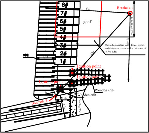
FIGURE 5. The location of nitrogen-injected drilling and plugging drilling corresponds to the downhole working surface.
4.3 Liquid nitrogen injection drilling arrangement
The direct injection of liquid nitrogen into the ground borehole has proven to be an efficient and rapid method for extinguishing high-temperature fires in the salt well area. In recent years, there have been several instances of large-scale liquid nitrogen fire-fighting using ground drilling during gas combustion fires and disaster relief events in China. Each liquid nitrogen fire extinguishing situation is unique, and some mines may face challenges with open area fire-fighting that require a larger amount of liquid nitrogen. To address these challenges, plugging measures such as the injection of polymer materials, water sealing into the air inlet section of the roadway, and other methods are combined with ground drilling injection to achieve fire extinguishing and rescue in the gas combustion explosion fire area.
Drilling in the roof of the coal seam, strengthening the measures such as mud displacement flow and drilling fluid performance system, geological logging, geological guidance, real-time fine drill bit regulation, real-time optimization control of borehole trajectory and other measures to control the wellbore trajectory in sandstone 2 m above the roof of the lower 10 coal seam.
The equipment of this project adopts the American schramminc T450 drilling rig, TZJ100 drilling rig, etc., to complete the major accident rescue tasks such as coal mine flood drainage and drilling, and participate in the ground drilling liquid nitrogen fire-fighting and rescue many times. The low temperature resistant drilling pipeline is used as the nitrogen injection casing, which is connected by pipe thread and matched with the drilling construction. It is connected to the liquid nitrogen tank truck, and the nitrogen injection flow rate can reach 10 t/h. A small amount of liquid nitrogen perfusion or vaporization of a small amount of liquid nitrogen vaporizer, to achieve the nitrogen injection pipeline cooling, to prevent the casing pipe heating uneven cracks. The material of P110 casing is mainly carbon steel. The temperature in the pipe is −196°C, and the linear expansion coefficient is 9.1 × 10⁻⁶. After calculation, the length of the assembly is 560 m, and the length is about 1.05 m due to low temperature shrinkage. Site construction layout of drilling rig is shown in Figure 6.
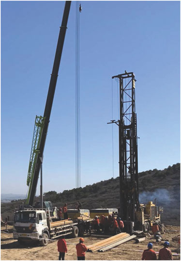
FIGURE 6. Drilling rig site construction.
4.4 Determination of liquid nitrogen flow
4.4.1 Determination of liquid nitrogen dosage
(1) Extinguishing and cooling the fire point directly by drilling precise positioning.
(2) To estimate the required amount of nitrogen injection, the residual combustion scale must be determined. This can be achieved by using a calculation model that considers the outlet air volume, temperature, O2 and CO concentration value of each wellhead reserved pipeline after liquid nitrogen injection. Once the residual combustion scale has been calculated, the remaining nitrogen injection amount can be estimated.
(3) To determine the amount of cooling nitrogen injection, the closed wall of the air shaft is subjected to pressure relief, and the change in outlet gas temperature is used to determine the nitrogen injection rate. A curve of the temperature change is then drawn, and when significant changes in temperature, CO, and O2 concentrations are observed, the nitrogen injection flow rate is reduced and controlled accordingly.
(4) Intermittent injection of nitrogen surplus can achieve the anticipated cooling and fire extinguishing effect if required.
Accurately measuring the amount of liquid nitrogen needed for fire extinguishing is challenging due to the heat exchange between underground space gas and surrounding rock. So employing empirical formula calculated by the inert index of oxygen content.
QN- The amount of nitrogen injection for fire extinguishing, m3;
V- Closed fire area volume, m3;
C1- Raw oxygen content before nitrogen injection in the fire zone (measured or averaged), %;
C2- Oxygen index after nitrogen injection for fire extinguishing (5%)
A preliminary estimate shows that 1000t of liquid nitrogen is required to cool completely burning wood cribs and fences. The nitrogen injection process is designed for 10 tons per hour, and it takes approximately 20–25 days to achieve fire extinguishing and cooling. During liquid nitrogen injection, the flow rate should be controlled when the downhole air temperature drops rapidly. After the air temperature reduces to 0°C, intermittent nitrogen injection is preferred. At this stage, the air and surrounding rock adequately exchange heat, preventing too rapid temperature reduction that can damage underground equipment and avoid unnecessary waste of nitrogen injection.
4.4.2 Liquid nitrogen flow determination process
1) The amount of underground fuel combustion is not clear, resulting in the amount of fire extinguishing liquid nitrogen is difficult to accurately measure.
The nitrogen is a low-temperature liquefied gas with a boiling point of-195.65°C at a pressure of 101.325 kPa. The temperature rises from −196°C to 0°C, and the heat absorption of nitrogen is 203 kJ/kg; The calorific value of 1 kg standard coal is 7000 kCal, the combustion calorific value of 1 kg pine is about 1700 kCal, about 0.5t of 1 m3 dry pine and about 0.8t of 1 m3 wet pine; the K2 coal seam is lean coal, Carbon content is 89%, hydrogen content is generally 4.2%, and the combustion calorific value is 24.41 MJ/kg. According to the complete combustion of wood stack and fence sheet, 1000t liquid nitrogen is needed to achieve fire cooling, In order to achieve safe and smooth unsealing, after the realization of fire suppression and cooling, the continuous intermittent supplement of temporary estimated injection is 2 times the surplus coefficient.
In the formula - the total nitrogen injection
The total volume of the mine roadway and goaf is estimated to be 1839000 m3. The mine is flooded at the level of −230 m, and the space of roadways and goafs of −150 m and above is 179.2 × 10⁴ m3, take
4.5 Precise positioning injection of nitrogen to extinguish fires
After a fire accident occurred at an underground coal face in a high gas outburst mine, all four shafts were closed for disaster relief. We first analyzed the development and spread trend of fire according to the fire occurrence location, combustion storage location and CO concentration, so as to determine the high temperature area, and finally determined the best drilling location in the high temperature area combined with the design drawings. It is determined that the construction 1 # nitrogen injection fire extinguishing hole is the underground end hole 15 m behind the coal side position and 15 m in the inclined upward back wind direction. To efficiently and rapidly extinguish the fire and ensure safe reopening, two boreholes were precisely constructed using a Sherm drill. These boreholes penetrated the goaf at the upper part of the coal face, facilitating the accurate positioning and large flow liquid nitrogen perfusion process.
The directional drilling method is a significant improvement over conventional techniques as it allows for multiple drilling into abandoned mine wellheads and processing the underground area from a surface location (Ozment and Trevits, 2018). It is important to maintain continuous ventilation during a mine fire, therefore, promptly plugging the fire zone into the return airway is not recommended as it will significantly increase the amount of liquid nitrogen required. Construction of the ground drilling platform and road in the return airway of the working face is difficult while sealing drilling construction in the intake airway of the working face requires ground platform conditions. Deviated drilling to the return airway for precise positioning of construction is costlier and not conducive to the implementation of casing plugging. Taking into account the implementation conditions of the construction platform, it has been determined that ground sealing drilling will be implemented at the air inlet end to ensure the safe and rapid unsealing of the salt well mine.
5 Analysis of fire extinguishing effect
5.1 Sampling analysis
5.1.1 Analysis of gas sampling in closed wall
This experiment during the ground drilling liquid nitrogen injection, shaft closed wall for methane, O2, CO, carbon 2 gas manual detection, monitoring equipment is mining gas detector, micro-GC is using gas chromatography principle mining portable instrument, capillary column and special micro thermal conductivity element, can meet the needs of mine daily measurement, and single chip machine control, storage data, and forecast natural ignition function. In order to ensure the comprehensive authenticity of the data, the sampling analysis of the wellbore closed wall detection pipeline is conducted every 4 h, and the sampling is sent for chromatographic analysis. The detection instrument is gas chromatography analyzer, which has many kinds of detectors, which can complete the analysis of all gases in the coal mine.
To analyze the changes in CO concentration, wellhead samples were collected before and after nitrogen injection. The following observations were made: 1) Before penetration of the 1# borehole, CH4 was emitted and O2 levels decreased, resulting in suffocation underground and a continuous decline in CO. 2) Following nitrogen injection, the gas pressure within the fire zone increased, causing the gas to flow from the center of the fire zone to the wellbore. 3) Due to a sustained increase in pressure within the enclosed underground space after the injection of liquid nitrogen, the maximum pressure difference exceeded 8000 Pa.The field headquarters decided to seal and relieve the wellhead.
After the pressure relief operation, nitrogen is injected into the underground space, which gradually replaces the other gases present. Monitoring sensors and analysis of gas samples taken from outside the sealed wellhead show a general decrease in CO concentration. After drilling hole 2#, a significant amount of gas pressure relief occurred, causing the CH4 concentration to reach up to 90% in the upper part of the fire zone and nearby areas. The monitoring data for pressure differences among the sealed wellheads decreased significantly to below 1,000 Pa. However, the CO accumulated in the underground space entered the air leakage line, causing the CO concentration of each closed wellhead to increase noticeably and the pressure difference to fluctuate markedly. Ground sealing was implemented in 2# drilling, and after a large amount of liquid nitrogen was injected and cooled the area, the CO concentration decreased to 0 PPm within 3 days, as shown in Figures 7A,B. These results indicate that the desired cooling effect was achieved for the fire zone, and the liquid nitrogen injection was stopped at the site.
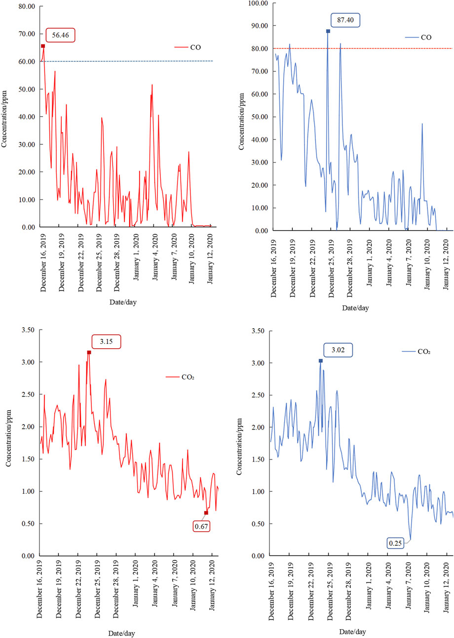
FIGURE 7. Variation of CO and CO2 concentration in return air shaft and man-vehicle inclined shaft.
After 1# and 2# drilling holes, the gas chromatograph was used to detect the gas in the wellhead closed wall. The results showed that CO, C2H4 and C2H2 continued to be 0 PPm, and the O2 concentration was less than 3%. It can be seen from Figure 7, Figure 8 that the concentrations of CO, CO2, N2, CH4 and O2 in each wellhead closed wall change.
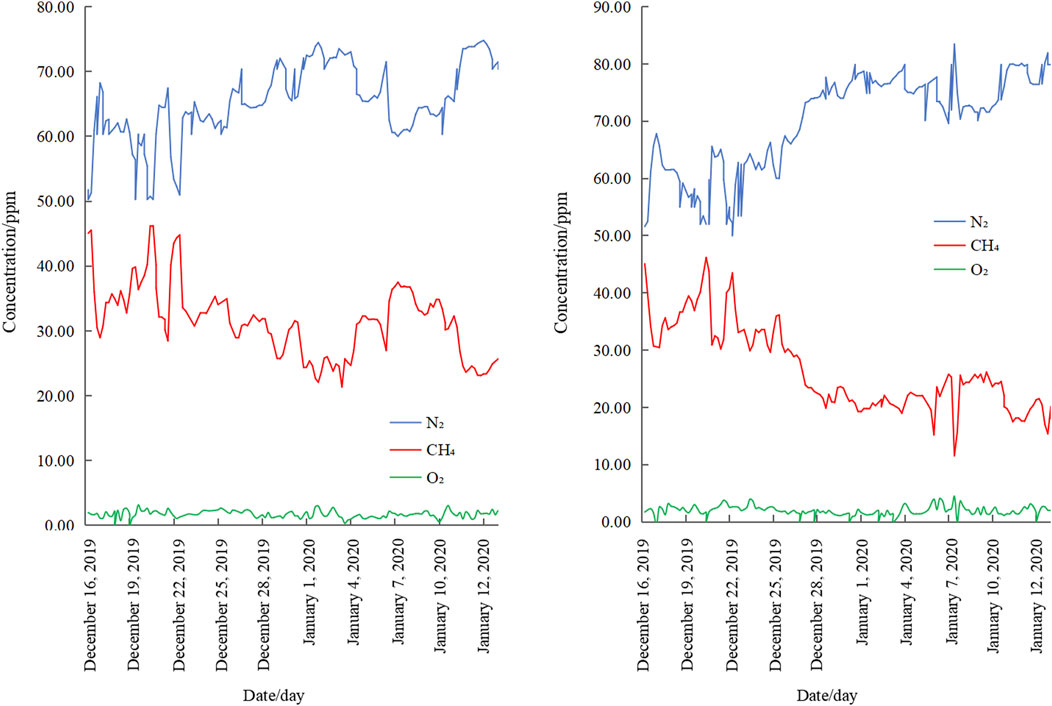
FIGURE 8. Variation of N2, CH4 and O2 concentration in return air shaft and man-vehicle inclined shaft.
5.1.2 Drilling hole sampling and analysis data
On October 26, Hole 1# was completed and confirmed to achieve precise positioning (offset 0.84 m).
The detection data indicated a significant presence of CH4 with a concentration of 90% and a maximum CO concentration of 230 PPm, which suggested the presence of a substantial amount of high concentration CO in the fire zone and the upper goaf. A large amount of incomplete combustion is occurring in the goaf, generating a large amount of CO, leading to the rise of CO content. A graphical representation of the results is provided in Figure 9A.
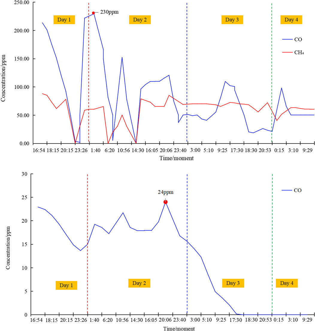
FIGURE 9. Gas concentration detection data in 1 # and 2 # boreholes.
On November 5, the 2# drilling completed the lower casing, and on November 6, it was repeatedly confirmed by inclination measurement and video peeping that the drilling hole was accurate in place (offset 0.99 m). The roof of the hole bottom fell to a certain extent, forming a certain amount of crushed coal rock accumulated around the bottom of the borehole casing of borehole No. 2, and the casing orifice was about 1.4 m away from the floor of the 2# coal seam.
After the 2# borehole penetrated the caving zone, gas detection data was collected from the borehole. The results showed that the concentration of CH4 was as high as 90%, and the highest concentration of CO was 24 PPm. During the continuous injection of nitrogen, the CO concentration and temperature in the 2# hole showed a significant decrease. It can be seen from Figure 9B that the CO concentration decreased from 24 PPm to 0 PPm, and the bottom temperature of 2 # borehole decreased from 30 C to 26 C. It shows that the fire extinguishing and cooling effect of liquid nitrogen injection was very obvious to the center of the fire area. Liquid nitrogen vaporizes by absorbing heat and lowering the temperature. At the same time, the volume expansion after gasification relatively reduces the content of CO, CH4 and other gas, but the heat exchange is still in the whole fire area, each gas is in a chaotic state, and CH4 is still incomplete combustion, leading to the rise of CO content in the later stage.
5.2 Effect analysis of fire extinguishing cooling and formation sealing
To ensure safe and effective liquid nitrogen injection for fire extinguishing, several measures must be taken during the ground drilling process. First, the air pressure in the closed well area should be maintained at 1.5 atmospheres, and the air outlet temperature should be kept above 0°C. Secondly, the nitrogen injection flow control should be adjusted based on the actual fire extinguishing effect and cooling situation on-site. Once the CO concentration is reduced to 0 PPm, and the air pressure is maintained at 1.5 atmospheres with an air outlet temperature around 0°C, it is recommended to switch from large-flow liquid nitrogen injection to controlled flow or intermittent liquid nitrogen injection for cooling before unsealing the shaft. This will ensure that there is full heat exchange between the underground gas and surrounding rock, creating favorable conditions for the safe and smooth opening of the seal. During the process of nitrogen injection, it is essential to manually test the wellbore sealing wall every hour and sample and analyze the testing pipeline every 4 hours to ensure the sealing wall’s integrity. After nitrogen injection has been stopped, manual inspections should be conducted at least once per shift, and sampling and analysis should be performed once a day before opening. All data should be collected and analyzed to track downhole changes promptly. These measures will help to ensure that the liquid nitrogen injection process is conducted safely and effectively. A comparative plot of ground plugging drill holes and stratigraphies is shown in Figure 10.
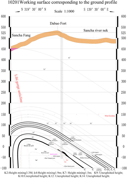
FIGURE 10. Ground plugging drill hole and stratigraphic comparison map.
The effect of fire extinguishing and cooling plugging was evaluated, and the three processes of field monitoring, sampling analysis and data detection were obtained.
(1) The results of borehole orifice detection data show that the CO concentration in the fire area decreases rapidly after liquid nitrogen injection. By injecting nitrogen into the goaf, it is necessary to dilute the oxygen in the original air. The lower the oxygen concentration in the goaf area, the slower the oxidation rate of floating coal is. The process of nitrogen injection is the process of reducing the oxygen content, that is, the process of slowing down the oxidation rate of coal, which is the process of nitrogen inertia and flame retardant. It indicates that nitrogen has begun to hinder the combustion reaction in local areas, resulting in the gradual reduction of CO generated, but the nitrogen in the goaf does not spread to the whole area, and its content is not enough to be completely flame retardant. Therefore, the combustion reaction still occurs at this stage.
(2) Ground drilling was conducted on 1# and more than 2,300 tons of liquid nitrogen were perfused with a large flow rate. Gas detection data analyzed at the wellhead’s closed wall revealed that liquid nitrogen injection was successful in extinguishing the fire in the area, achieving the desired outcome of fire cooling. The CO concentration at the wellhead has decreased to 0 PPm and has remained stable for three consecutive days.
(3) After blocking the ground, 308 cubic meters of cement fly ash slurry are poured into the borehole until the ground pipe mouth is filled to the expected level.
The ground drilling technique was utilized to precisely locate the fire zone, and the use of liquid nitrogen effectively extinguished and cooled the high-temperature fire. Compared to conventional fire extinguishing methods, this technique presents unparalleled advantages. The fire extinguishing and cooling targets were achieved, as well as ground drilling plugging, with no occurrences of repetition or fluctuation. This achievement has created a favorable environment for safe and unobstructed unsealing.
6 Closed fire area unsealed
6.1 Overall plan for unsealing
Based on the increasing gas concentration in the enclosed underground space after mine closure, an estimated amount of 40 m3/min of gas is expected to gush out from underground. However, the temporary ventilation system and the pressed-in fans of the underground ventilation line can only handle 500–800 m3/min of air volume. The gas discharge process takes a long time, making it challenging to maintain the gas concentration in the tunnel and return side below the limit. To address this, the overall unsealing plan of the project is divided into three stages.
The first stage involves preparing for the unsealing operation, which includes confirming the unsealing operation conditions and obtaining approval from experts. In the second stage, closed demolition is implemented using the main fan gas to create underground negative pressure, which minimizes air leakage in the return air shaft and auxiliary inclined shaft. This stage is comprised of several steps: 1) forming underground negative pressure; 2) blasting and demolishing the closed return air shaft; 3) closing the explosion-proof door, butterfly valve, and pedestrian door to establish a downhole negative pressure, and dismantling the auxiliary inclined shaft; 4) returning the air shaft and auxiliary inclined shaft and controlling air volume and negative pressure ventilation once the CH4 concentration has decreased to 0.75%.; 5)At this point, the temporary base of the depot is established 50 m below the well’s bottom, and the ambulance team investigates and temporarily closes the intake and return air roadway of the working face; 6) The final step in this stage is closing the intake and returning air roadway of the working face once the mine’s temporary recovery system and conditions are available. In the third stage, the closed walls of the main inclined shaft and car inclined shaft are unsealed, and full negative pressure ventilation is restored.
6.2 Pressure relief in the underground space before unsealing
The gas drainage pump station’s gas drainage pump is utilized to alleviate pressure in the enclosed space. Before starting the pump to relieve pressure, safety measures are confirmed throughout the underground space pressure relief process to ensure that the pressure remains below 1 standard atmosphere. As pressure is relieved, the concentration of CH4 in the underground gas decreases continuously until it falls within the explosion limit concentration range. Gas chromatography is used to analyze samples taken during each shift from the reserved pipeline of the sealed wall, the drilling pipeline of the ground, and the extraction pipeline to confirm that CO, C2H4, and C2H2 remain at 0 PPm without abnormal changes. The precise drilling of a small amount of liquid nitrogen at ground level has created an outward wind from the area of the 10,201 working face.
To ensure safety during the pressure relief process in the underground space, safety confirmation is carried out when the gas drainage pump is activated. The concentration of CH4 in the underground gas is gradually reduced to the explosive limit concentration range. Gas samples are taken from the underground gas via the reserved closed wall, ground drilling, and drainage pipelines, and are analyzed using a gas chromatograph every shift to confirm that the concentration of CO, C2H4, and C2H2 remains within normal ranges without any abnormal changes, and is maintained at 0 PPm. Figure 11 illustrates the concentration curve of CH4 over time.
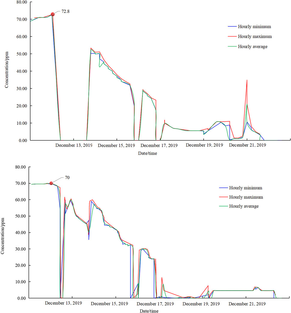
FIGURE 11. Detection data of CH4 concentration in the closed wall of man-vehicle inclined shaft and main inclined shaft.
6.3 Return air shaft closed wall blasting demolition
Yanjing No. 1 Mine organized and implemented the protection of explosion-proof doors and butterfly doors, monitoring sensor installation, main fan testing, firing busbar installation, press-in fan installation, compressor installation, sprinkler spray pipeline and slag belt preparation before the concrete closed wall blasting and demolition, and organized the acceptance confirmation item by item. And the gun hole construction was carried out in advance, and then the concrete closed wall blasting and demolition of the return air well began, the specific process is as follows: 1) Open the pipeline on the closed wall of the return air shaft in advance as the inlet air, and confirm that the closed wall of the return air shaft is in a negative pressure state; 2) Strict implementation of the ‘one gun three inspection’, CH4 concentration is less than 1%; 3) Site Management According to Safety Standardization of Tunneling Face; 4) Multi-cycle tunneling, drilling once in each cycle, fractional charging, fractional blasting; 5) Strictly implement the prohibition of firing artillery; 6) Strict management of explosive detonators and other fireworks; 7) On-site inspection and confirmation of the charge.
6.4 Demolition of the closed wall of the secondary inclined shaft
After the blasting demolition of the concrete closed wall of the return air shaft and the cleaning of the sandbag wall, the explosion-proof door, butterfly door and pedestrian door of the return air shaft are closed, and the underground negative pressure is formed by extraction, and the closed wall pipeline of the auxiliary inclined shaft enters the air. Then began the auxiliary inclined shaft concrete closed wall demolition, and completed the auxiliary inclined shaft closed wall demolition and sandbag cleaning. In the process of removing the closed wall, through the reserved pipeline, ground drilling pipeline and drainage pipeline of the closed wall of the main inclined shaft and the man-vehicle inclined shaft, the underground gas sampling and analysis were carried out to confirm that the concentrations of CO, C2H4 and C2H2 did not change abnormally and continued to be 0 PPm.
6.5 Main fan drains underground gas
During the process of underground anti-air and negative pressure gas drainage, the maximum concentration of CH4 was 13.7% when discharged by the main fan. However, it remained within the explosion limit for a prolonged period. The concentrations of CO, C2H4, and C2H2 remained at 0 PPm without any abnormal changes, as confirmed by underground gas sampling analysis through the reserved pipeline of the main inclined shaft, the vehicle inclined shaft closed wall, ground drilling pipeline, and drainage pipeline. Afterward, negative pressure gas was initiated. Figures 12–15 illustrates the changes in CH4 concentration and wind speed in the return air shaft, the front, and rear auxiliary inclined shafts during the process of main fan reverse air exhaust gas and negative pressure ventilation exhaust gas.
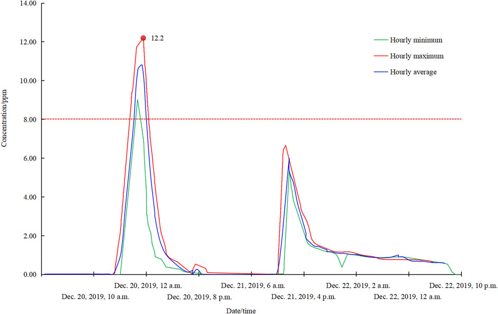
FIGURE 12. Changes in the concentration of CH4 in the return air well during the reverse wind gas discharge and negative pressure ventilation gas discharge of the main fan.
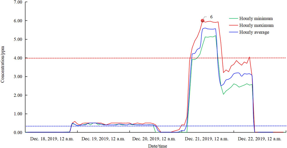
FIGURE 13. Changes in the wind speed of the return air shaft during the reverse wind gas discharge and negative pressure ventilation gas discharge of the main fan.
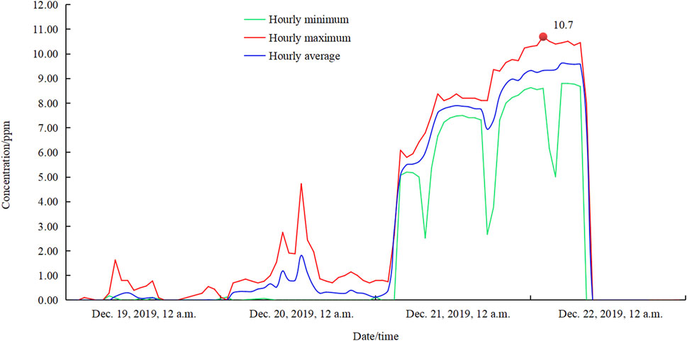
FIGURE 14. Changes in the wind speed of the auxiliary inclined shaft before and after the reverse wind gas discharge and negative pressure ventilation gas discharge of the main fan.
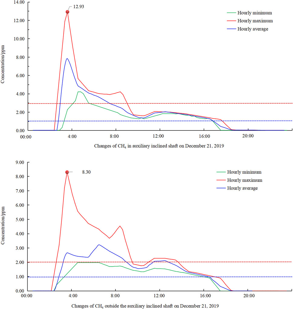
FIGURE 15. Variation of CH4 concentration inside and outside the auxiliary inclined shaft during the main fan reverse ventilation and negative pressure ventilation.
The press-in ventilation backwind effectively reduced the CH4 concentration at the outlet of the sub-inclined shaft to less than 0.75% for a longer duration than what was initially estimated. An analysis revealed that this was due to higher CH4 concentration accumulated in the goaf and roadway space than that in the main line. Similarly, during negative pressure ventilation and gas drainage, the time for the CH4 concentration in the return air shaft to decrease to 0.75% was longer than expected. This was because the CH4 stored in the underground excavation area was discharged through the hard air duct set on the damper in the mine, under the condition of negative pressure ventilation. It was calculated that the total gas storage space in the underground boring area was 19,637 m3.
6.6 The ambulance team undergoes reconnaissance and closes the working surface
Before the ambulance team descended into the mine, the closed wall was fitted with a pipeline and an extraction pipeline to sample and analyze the downhole gas, which confirmed that CO, C2H4, and C2H2 concentrations were continuously at 0 PPm with no abnormal fluctuations. The return air roadway of the 10,201 working face was investigated for gas temperature, blockage, and air leakage. The results showed that the inlet end was well-blocked with no obvious air leakage, the local maximum temperature of the roadway roof was 44°C, and the maximum CO concentration detected in the return air lane was 110 PPm. Air leakage volume detection was carried out, and the results showed that the air leakage rate was 20 m3/min, confirming the safety of the plugging process. The sealing work of the two alleys of the working face was immediately initiated, using fire doors to construct the brick wall sealing.
The research project was conducted between October 26 and 15 November 2019. During this period, ground fire extinguishing and cooling nitrogen injection, ground sealing construction, monitoring analysis, and opening plan preparation were completed. From October 26 to December 15, intermittent liquid nitrogen injection was carried out, and program discussions were held to refine the plan for unsealing. Preparations for unsealing were made from 16 December 2019, to 15 January 2019. The results show that sealing can be implemented 30 days after the CO concentration of the mine reaches the standard and stabilizes. The shaft opening time can meet the requirement of being 50 m free from water gusher, and the technical time, progress, and risk of fire extinguishing can be controlled.
7 Summary
After an open fire occurred in the mine with high gas outburst, the " dual-drive " super large fire strategy can achieve efficient fire extinguishing and cooling, and curtain grouting to seal the entire mine. This method determines a reasonable sealing sequence for the large fire area, safely accomplishing the sealing of the large fire area, and effectively preventing secondary accidents such as gas explosions and the spread of the fire’s influence area during the sealing process.
(1) The mine experienced high gas outbursts and an underground fire, which were promptly addressed using the rapid injection of a large flow rate of liquid nitrogen and ground precise positioning of drilling holes to achieve efficient fire cooling and curtain grouting sealing. The reasonable closure sequence of the large-scale fire area was determined to ensure its safe closure, and the process of sealing effectively prevented the risk of secondary accidents such as gas explosions and the spread of fire influence. To effectively block the air inlet end of the coal mining face, cement fly ash slurry curtain grouting was used, and accurate positioning was achieved by drilling on the ground and monitoring the collapse of coal and rock at the bottom of the hole via video. The cement fly ash slurry passed through the borehole casing, the lower sieve tube, and curtain grouting was carried out to achieve effective sealing of the inlet end and the inlet lane. The plugging time was determined to effectively extinguish the fire after nitrogen injection, and the CO concentration was reduced to 0 PPm in the downhole space to plug the high-temperature area on the inlet side of the plugging section. This approach effectively prevented the rapid re-ignition of the high-temperature area during gas drainage, facilitated efficient fire extinguishing, cooling, and curtain grouting sealing, and created favorable conditions for the safe unsealing of the mine.
(2) The fire extinguishing effect of a large-scale closed fire area was accurately identified by conducting underground space pressure relief and gas sampling analysis. The effectiveness of fire extinguishing, cooling, and plugging in the underground fire area was determined through drilling construction, nitrogen injection, and plugging, as well as continuous sampling and analysis of the ground drilling and mine shaft sealing process wall. The reduction of CO concentration to 0 PPm and O2 concentration to less than 3% in the downhole space was attributed to the completion of liquid nitrogen injection for fire cooling and sealing on the ground. These results demonstrate the remarkable sealing effect of the dual-drive rapid fire extinguishing technology for ultra-large high gas mines, with no observed repetition or fluctuation. This creates favorable conditions for the safe and smooth unsealing of the mine. After the completion of surface liquid nitrogen injection extinguishing, cooling and sealing, the concentration of CO in underground space decreased from 230 PPm to 0 PPm, and the concentration of CH4 decreased from 90% to less than 3%. These results indicate that the ‘dual drive’ fire system employed in this project had a remarkable effect on rapidly extinguishing the fully closed mine without any repetition or fluctuations, creating favorable conditions for the safe and smooth opening of the mine.
(3) The technical scheme for safe and efficient unsealing of the large-scale closed fire area was scientifically determined. Ground-fixed gas drainage pumps were utilized to remove high-concentration gas accumulated in the underground space. Ground fixed gas drainage pump is used to drain high concentration gas accumulated in underground space. When the negative pressure state is formed in the drainage space and the CH4 concentration near the closed wall is confirmed to be less than 1%, the concrete closed wall is demolished by blasting. The formation of a return ventilation system, using the main fan pressure ventilation, drainage of underground space accumulation of high concentration gas. After confirming that the outlet CH4 concentration is lower than 0.75%, the main fan extraction ventilation is used to discharge the gas accumulated in the underground space.
Data availability statement
The original contributions presented in the study are included in the article/Supplementary material, further inquiries can be directed to the corresponding author.
Author contributions
YM: Writing–original draft, Writing–review and editing, Resources, Conceptualization, Data curation, Formal Analysis, Funding acquisition, Investigation, Methodology, Project administration
Funding
The author(s) declare that no financial support was received for the research, authorship, and/or publication of this article.
Conflict of interest
Author YM was employed by China Coal Technology & Engineering Group.
Publisher’s note
All claims expressed in this article are solely those of the authors and do not necessarily represent those of their affiliated organizations, or those of the publisher, the editors and the reviewers. Any product that may be evaluated in this article, or claim that may be made by its manufacturer, is not guaranteed or endorsed by the publisher.
References
Bacharach, J. P. L., Craven, A. L., and Stewart, D. B. (1986). Underground mine fire control with in-erting systems. Cim. Bull. 79, 67–72. doi:10.4095/304744
Banerjee, S. P. (1987). Nitrogen flushing in coal mines as a measure against mine fires. Trans. Min. Geol. Metall. 84, 1–9.
Bobo, S., and Fubao, Z. (2014). Impact of heat and mass transfer during the transport of nitrogen in coal porous media on coal mine fires. Sci. World J. 2014, 1–9. doi:10.1155/2014/293142
Christopher, J. B. (2013). American coal mining: methods and applications. Englewood, CO, United States: Mining Engineering, Society for Mining, 65. doi:10.1016/j.fuel.2013.09.070
Cloves (2014). Numerical simulation of low-temperature nitrogen injection in goaf[D]. China University of Mining and Technology.
Deming, W., Guolan, D., Xiaoxing, Z., Xin, H., and Qin, B. (2014). An experimental approach to selecting chemical inhibitors to retard the spontaneous combustion of coal. J. Fuel 117, 218–223. doi:10.1016/j.fuel.2013.09.070
Dong, W., Wang, X., Shi, B., and Wang, K. (2011). Research and application of liquid nitrogen fire prevention and extinguishing technology in open area in Yangchang Bay coal mine_Dong Wei. Coal Eng. (12), 47–49. doi:10.3969/j.issn.1671-0959.2011.12.020
Dudley, M., Caroline, S., and Frank, A. (2019). Morwell coal mine fire as a cascading disaster: a case study. Prehospital Disaster Med. 34 (s1), s8. doi:10.1017/S1049023X19000360
Fauconnier, C. J., and Meyer, M. J. R. (1986). Conceptual mathematical models for the injection of nitrogen into sealed colliery fires. J. S Afr. Inst. Min. Metall. 86, 81–88. doi:10.520/AJA0038223X_1563
Geng, J., Cao, L., Zhong, C., Wang, H., and Baiqiao, C. (2023). Investigation of dynamic response of drilling parameters and deformation characteristics of coal around borehole during multi-stage reaming in tectonic coal. Int. J. Rock Mech. Min. Sci., 170. doi:10.1016/j.ijrmms.2023.105540
Hiroyuki, T., Miho, I., and Akihiko, I. (2016). Examination of extinguishment method with liquid nitrogen packed in a spherical ice capsule. Fire Technol. 52 (4), 1179–1192. doi:10.1007/s10694-015-0534-6
Hu, X., Yang, S., Zhou, X., Yu, Z., and Hu, C. (2015). Coal spontaneous combustion prediction in gob using chaos analysis on gas indicators from upper tunnel. J. Nat. Gas Sci. Eng. 26, 461–469. doi:10.1016/j.jngse.2015.06.047
Li, Q. (2014). Drilling technology of directional borehole for over-slurry reinforcement of coal seam floor. Coal Sci. Technol. 42 (01), 138–142. doi:10.13199/j.cnki.cst.2014.01.032
Lin, J., Ren, T., Wang, G., Booth, P., Cheng, Y., Black, D., et al. (2022). Field trials of nitrogen injection enhanced gas drainage in hard-to-drain coal seam by using underground in-seam (UIS) boreholes. Fuel 328, 125293. doi:10.1016/J.FUEL.2022.125293
Ma, D., Duan, H., Zhang, J., and Bai, H. (2022b). A state-of-the-art review on rock seepage mechanism of water inrush disaster in coal mines. Int. J. Coal Sci. Technol. 9, 50. doi:10.1007/s40789-022-00525-w
Ma, D., Duan, H., Zhang, J., Liu, X., and Li, Z. (2022a). Numerical simulation of water-silt inrush hazard of fault rock: a three-phase flow model. Rock Mech. Rock Eng. 55, 5163–5182. doi:10.1007/s00603-022-02878-9
Ma, D., Li, Q., Cai, Kc., Zhang, J. x., Li, Z. h., Hou, W. t., et al. (2023). Understanding water inrush hazard of weak geological structure in deep mine engineering: a seepage-induced erosion model considering tortuosity. J. Cent. South Univ. 30, 517–529. doi:10.1007/s11771-023-5261-4
Mohalik, N. K., Singh, R. V. K., Pandey, J., and Singh, V. K. (2005). Application of nitrogen as preventive and controlling subsurface fire–Indian context. 64 (4), 273–280.
Mykola, A., Vadym, T., and Olha, Z. (2019). Analysis of fire and hazardous sites (zones) in coal mines and the causes of coal self-ignition[J. ]. Technol. Audit Prod. Reserves 6 (3). doi:10.15587/2312-8372.2019.185953
Ozment, A., and Trevits, M. A. (2018). New application of directional drilling and gas-enhanced foam for suppression of abandoned underground coal mine fires. Min. Eng. 70 (5). doi:10.1016/j.ijggc.2012.09.006
Pandey, J., Mohalik, N. K., Mishra, R. K., Khalkho, A., Kumar, D., and Singh, V. K. (2015). Investigation of the role of fire retardants in preventing spontaneous heating of coal and controlling coal mine fires. Fire Technol. 51 (2), 227–245. doi:10.1007/s10694-012-0302-9
Rakesh, K. M., Roy, P. N. S., Virendra, K. S., and Pandey, J. K. (2018). Detection and delineation of coal mine fire in Jharia coal field, India using geophysical approach: a case study. J. Earth Syst. Sci. 127 (8), 107. doi:10.1007/s12040-018-1010-8
Ray, S. K., and Singh, R. P. (2007). Recent developments and practices to control fire in undergound coal mines. Fire Technol. 43 (4), 285–300. doi:10.1007/s10694-007-0024-6
Shekharsharan, M. (2009). Coal mine fire - an overview and methods to deal alongwith some case studies. J. Mines, Metals Fuels 57 (11).
Shen, Y., and Guo, J. (2009). Gas safety prevention in excavation of Xiangjiaba hydropower station. Yangtze River 40 (5), 98–100. doi:10.16232/j.cnki.1001-4179.2009.05.013
Shi, B. B., Ma, L. J., Dong, W., and Zhou, F. (2015). Application of a novel liquid nitrogen control technique for heat stress and fire prevention in underground mines. J. Occup. Environ. Hyg. 12 (8), D168–D177. doi:10.1080/15459624.2015.1019074
Sun, R., Wang, H., Zhou, X., and Sun, Z. (2011). Safety analysis and discrimination criteria for unsealing in mine fire area. China Saf. Sci. Technol. 7 (8), 42–46. doi:10.3969/j.issn.1673-193X.2011.08.007
Sun, Z., and Yin, Z. (2006). Study on the law of gas outflow during reverse wind in mine. Hebei Coal (1), 18–19. doi:10.3969/j.issn.1007-1083.2006.01.009
Vaughan-Thomas, T. (1964). The use of nitrogen in controlling an underground fire at fernhill colliery. Min. Eng. 123, 311–336.
Wang, H., Van, E. P. J., Medwell, P. R., Birzer, C. H., Tian, Z. F., and Possell, M. (2017). Effects of oxygen concentration on radiation-aided and self-sustained smoldering combustion of radiata pine. Energy & Fuels 31 (8), 8619–8630. doi:10.1021/acs.energyfuels.7b00646
Wastell, E. R., and Walker, G. (1983). The use of nitrogen in fryston colliery. Trans. Inst. Min. Eng. 142, 27–36.
Xu, l, Wang, d, and Zhang, w (2014). Statistical analysis of coal mine gas combustion accident. J. Coal Technol. 33 (10), 33–35. doi:10.13301/j.cnki.ct.2014.10.013
Xue, J. Z., Xing, L. W., Jie, P., Lin, H. G., and De, M. Q. (2012). Application study on technology of closure by curtain grouting in mine two of dongfeng coal mine. Adv. Mater. Res. (446), 1615. doi:10.4028/www.scientifific.net/AMR.446-449.2002
Xue, S., Dickson, B., and Wu, J. (2008). Application of 222Rn technique to locate subsurface coal heatings in Australian coal mines. Int. J. Coal Geol. 74 (2), 139–144. doi:10.1016/j.coal.2007.11.005
Yan, N. (2016). The application of directional long borehole in coal mine O ash water damage control. Saf. Coal Mines 47 (04), 165–167. doi:10.13347/j.cnki.mkaq.2016.04.044
Yang, X., Wang, G., Du, F., Jin, L., and Gong, H. (2022). N2 injection to enhance coal seam gas drainage (N2-ECGD): insights from underground field trial investigation. Energy 239 (PC), 122247. doi:10.1016/J.ENERGY.2021.122247
Yin, S. (2017). Interpretation and discussion of the key points of the revision of the new version of the Coal Mine Safety Regulations (water prevention and control part). Coal Sci. Technol. 45 (7), 139–143. doi:10.13199/j.cnki.cst.2017.07.025
Zhao, D., and Wang, B. (2007). Layout technology of longwall comprehensive discharge mining face of sharp-inclined thick coal seam. J]. Saf. Coal Mines (8), 40–43. doi:10.3969/j.issn.1003-496X.2007.08.014
Zhao, J. T., and Xue, L. L. (2012). Research on technology for preventing spontaneous combustion of coal. Adv. Mater. Res. (524), 1792. doi:10.4028/www.scientific.net/AMR.524-527.677
Keywords: high gas outburst coal mines, super large fire, dual-drive, unsealing the whole mine, grouting sealing
Citation: Mei Y (2023) A rapid dual-drive technology for extinguishing large high-gas coal mines fires. Front. Earth Sci. 11:1269092. doi: 10.3389/feart.2023.1269092
Received: 29 July 2023; Accepted: 08 November 2023;
Published: 28 December 2023.
Edited by:
Jun Lu, Shenzhen University, ChinaReviewed by:
Weizhong Zhang, Wuhan Institute of Technology, ChinaWensong Wang, Chengdu University of Technology, China
Copyright © 2023 Mei. This is an open-access article distributed under the terms of the Creative Commons Attribution License (CC BY). The use, distribution or reproduction in other forums is permitted, provided the original author(s) and the copyright owner(s) are credited and that the original publication in this journal is cited, in accordance with accepted academic practice. No use, distribution or reproduction is permitted which does not comply with these terms.
*Correspondence: Yong Mei, bWVpeW9uZy5nb29kQDE2My5jb20=