 Anis Khalifeh-Soltani
 Seyed Ahmad Alavi1
 Reza Derakhshani
- 1Department of Sedimentary and Oil Basins, Faculty of Earth Sciences, Shahid Beheshti University, Tehran, Iran
- 2Research Institute for Earth Sciences, Geological Survey of Iran, Tehran, Iran
- 3School of Geology, College of Science, University of Tehran, Tehran, Iran
- 4Department of Geology, Shahid Bahonar University of Kerman, Kerman, Iran
- 5Department of Earth Sciences, Utrecht University, Utrecht, Netherlands
Fault-related folds are intriguing geological structures that develop in compressional and extensional regimes. These folds serve as structural traps for hydrocarbon resources, making their numerical models crucial for understanding the stress and strain evolution of hydrocarbon reservoirs. In our research, we utilize the two-dimensional finite element technique to simulate three representative categories of fault-related folds. Our investigation encompasses their geometric transformation over time, the distribution of stress and strain, variations in slip and uplift, and the effects that various mechanical properties have on these gradients. In our study, we uncovered essential findings about the behavior of fault-related folds. We ascertained that the fault slip gradient in the fault-bend fold model is less than in the fault-propagation fold model. Regarding the uplift gradient, the fault-propagation and fault-bend fold models displayed the greatest and the least degree of change, respectively. The trend of stress-strain evolution on the fold surface in all models was consistent, starting with an increase, transitioning to a constant phase, and ending with a decrease. This pattern proved to be more intricate and divergent than what was evident on the fault surface. Importantly, the internal friction angle, a crucial mechanical characteristic, had a significant influence on the development of these structures. This angle affected both the degree of uplift and stress; an increased angle resulted in enhanced uplift and stress, while a decrease resulted in a decline. Furthermore, the internal friction angle determined the compactness of the fold and the thickness of the forelimb, the part of the fold that inclines towards the advancing direction. These findings have enriched our knowledge of fault-related folds, highlighting the need to consider mechanical properties when studying their formation and evolution.
1 Introduction
Fault-related folds form under both compressional and extensional conditions, as noted by (Mitra, 1993; McClay, 2011; Morley and Jitmahantakul, 2020). These structures can serve as structural traps that house hydrocarbon resources (McClay, 1995; Kent and Dasgupta, 2004). Therefore, multiple methodologies, such as field and seismic studies, analogue sandbox experiments, and numerical modelling, have been employed to study fault-related folds (Allmendinger, 1998; Hughes and Shaw, 2015; Ghanbarian and Derakhshani, 2022b; Ghanbarian and Derakhshani, 2022a).
Fault-related folds can be broadly classified into three primary types: fault-bend folds, as described by (Berger and Johnson, 1980; Suppe, 1983; Brandes and Tanner, 2014); fault-propagation folds, detailed by (Mitra, 1990; Suppe and Medwedeff, 1990; Brandes and Tanner, 2014); and detachment folds, as explored by (Epard and Groshong, 1995; Homza and Wallace, 1995; Homza and Wallace, 1997; Poblet and McClay, 1996).
Fault-bend folds are formed by material movement along a flat-ramp-flat path, where the geometry of the ramp controls the geometry of the folding. Fault-propagation folds originate due to the continuous decrease of slip on a spreading thrust fault, as explained by (Suppe and Medwedeff, 1990; Rashidi et al., 2023). A distinguishing feature of these faults is the localized folding at their extremities, typically resulting in either steep or capsized forelimbs, according to studies by (Suppe and Medwedeff, 1990; Hughes et al., 2014; Hughes and Shaw, 2015). Lastly, detachment folds are formed above a decollement or a detachment, as described by (Poblet and Stuart, 1995; Poblet et al., 1997; Rowan, 1997; Scharer et al., 2004). A detachment refers to a low-angle fault that runs nearly parallel to a horizon, on the other hand, a decollement corresponds to a fault that aligns parallel to a layer or stratum (Peacock, 2002).
Past research on detachment folds has examined factors such as the slope of the detachment surface (Axen et al., 2001; Zhou et al., 2018; Gan et al., 2020), the potential existence of an extra detachment layer (Barani, 2012; Hansberry et al., 2014; Morley and Jitmahantakul, 2020), and the mechanical properties inherent to the detachment layer (Cui et al., 2020; Vásquez-Serrano et al., 2021). However, these studies primarily focused on presenting geometric and kinematic models (Poblet and McClay, 1996; Liu et al., 2009; Lutz et al., 2021). Regarding fault-bend folds, the research conducted has incorporated both field observations and seismic investigations (Alvarez-Marron, 1995; Cook and MacLean, 1999; Qayyum et al., 2015). Additionally, studies have offered geometric and kinematic frameworks (Johnson and Berger, 1989; Hardy, 1995; Plotek et al., 2021), along with analogue models (Maillot and Koyi, 2006; Zanon and Gomes, 2019; Plotek et al., 2021), and numerical simulations of these folds (Poblet and Stuart, 1995; Poblet, 2020; Plotek et al., 2021). These investigations have explored the impact of the ramp dip (Johnson and Berger, 1989; Maillot and Koyi, 2006; Ju et al., 2014), the rate of displacement (Hughes et al., 2014; Hughes and Shaw, 2015; Jiang et al., 2020), the friction coefficient (Hughes et al., 2014; Ju et al., 2014; Hughes and Shaw, 2015), as well as the influence of the growth strata development and erosion (Poblet and Stuart, 1995) on fault bend folds. It can be concluded from the research subjects that the slope and mechanical properties of detachment surface, ramp geometry, mechanical properties of layers, displacement rate, friction coefficient, growth strata, and erosion are all parameters that control deformation and strain distribution in fault-related folds.
Various techniques for modelling geological structures numerically involve finite element analysis, boundary element analysis, and discrete element analysis. The finite element method is employed in this study to simulate fault-related folds (Smart et al., 2012; Yang et al., 2017; Li et al., 2020; Khalifeh-Soltani et al., 2023), while other studies have utilized boundary element analysis (Cooke and Pollard, 1997; Maerten et al., 2014), and discrete element analyses (Finch et al., 2002; Hardy and Finch, 2006) for their investigations. In this study, we use the finite element method to model fault-related folds. This approach involves dividing the object or structure into smaller segments known as elements. The elements are connected through a series of points or surfaces called nodes. The characteristics of the nodes are determined by the mechanical attributes of the materials that constitute the structure. All models utilized in this study exhibit an elastic-plastic rheology.
Indeed, this research employs the 2D finite element method to model the three primary types of fault-related folds. Then these models’ geometrical evolution, stress-strain pattern, plastic strain distribution, and slip and uplift gradients are compared. Subsequently, the study explores how mechanical properties, including density, Poisson’s ratio, Young’s modulus, internal friction angle, cohesion, and dilation angle, impact the slip and uplift gradients of these fault-related folds. After finding the effective mechanical parameter on slip and uplift gradients, the role of that parameter on stress-strain pattern and thickness of the forelimb is investigated. It is important to note that prior work has explored the impact of these parameters on fault-propagation folds using both 2D (Khalifeh-Soltani et al., 2021a) and 3D (Khalifeh-Soltani et al., 2021b) models. Khalifeh-Soltani et al. (2021a) investigated the impact of internal friction angle on fault-propagation fold geometry. Also, Khalifeh-Soltani et al. (2021b) examined the role of ramp geometry on the slip and uplift gradients of the fault-propagation fold. However, in this research, with the aim of comparing the outcomes of the three primary types of fault-related folds, a new set of 2D finite element models are introduced to simulate fault-propagation folds.
2 Modelling
In this research, fault-propagation, fault-bend, and detachment folds are emulated using ABAQUS™ software (version 2017). The study further explores the impacts of alterations (±20%) in six distinct mechanical attributes (density, Poisson’s ratio, Young’s modulus, internal friction angle, cohesion, and dilation angle) on the gradients of uplift and slip through the development of 12 additional models for each end member of fault-related folds. To scrutinize the effects of each parameter on slip and uplift gradients, the model simplification was mandated to restrict the variable number, as suggested in previous studies (Smart et al., 2012; Khalifeh-Soltani et al., 2021a; Khalifeh-Soltani et al., 2021b). Consequently, geological processes such as isostasy, fluid flow, growth strata, and pressure solutions are not taken into account in the present study.
Hooke’s law, consisting of Young’s modulus and Poisson’s ratio, is adopted for elastic aspects of the material, while the standard Mohr-Coulomb formulation is employed for the plastic properties. These mechanical attributes of the materials are used as the input variables for the model, allowing us to assess the effect of altering each parameter on the fold geometry. Consistent with previous research (Khalifeh-Soltani et al., 2021a; Khalifeh-Soltani et al., 2021b), all models encompass five layers whose mechanical properties correspond to stratigraphic units found in the Zagros fold-and-thrust belt (as depicted in Figure 1 and detailed in Table 1).
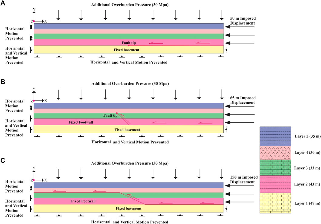
FIGURE 1. Setup of the finite element models; (A) detachment fold model, (B) fault-propagation fold model, (C) fault-bend fold model.
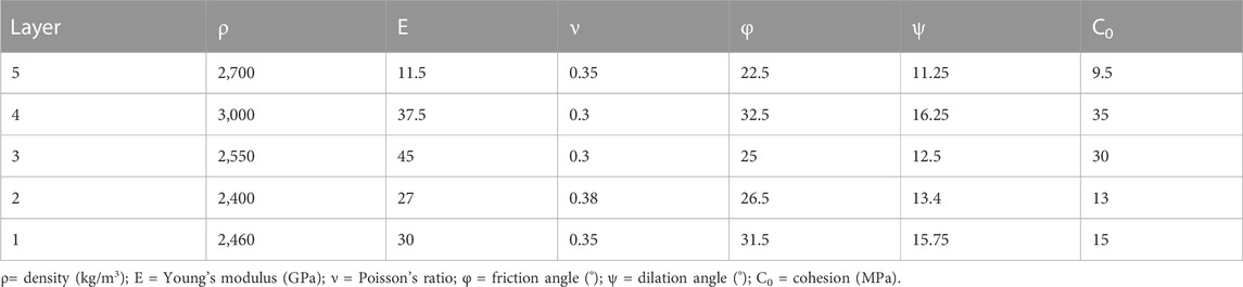
TABLE 1. Material properties are used in all reference models.
The study adopts the same boundary conditions and friction coefficient as those employed by Smart et al. (2012), as illustrated in Figure 1. Therefore, the conventional Coulomb friction model is utilized to account for the frictional sliding interfaces present between faults and layers:
where τcrit, σN, and μ are the critical shear stress, normal stress and friction coefficient, respectively (Smart et al., 2012). For all models employed in this study, the friction coefficient was set at 0.01 for fault interfaces and 0.25 for layer interfaces.
The dimensions of all models under investigation measure 1,200×190 m^3, as illustrated in Figure 1. In the fault-propagation and fault-bend fold models, the fault exhibits dips of 25° and 45°, respectively, as depicted in Figure 1. As the fault-related folds progress from detachment to fault-bend configurations with escalating displacement (Dobson, 1991), the lowest and highest displacements of 50 m and 150 m are respectively considered for the detachment and fault-bend models. Additionally, an intermediate displacement of 65 m is considered for the fault-propagation fold models.
In our study, a uniform assumption was made regarding the burial depths of all models, which were considered to be 1.5 km at the time of fold formation. To simulate these burial depths, an additional overburden pressure of 30 MPa was applied to the fifth layer, following the methodology proposed by (Ferrill, 1991; Ferrill and Groshong, 1993; Smart et al., 2012), as depicted in Figure 1.
For all models examined in this research, identical boundary and loading conditions were utilized, involving three consecutive simulation steps. Initially, a gravity load was applied to the complete model during the first step. Subsequently, in the second step, an extra overburden pressure of 30 MPa was imposed on the top of the model to replicate the assumed burial depth. Finally, a prescribed displacement was enforced to emulate the folding process. Notably, in the detachment fold model, the basement was held fixed throughout the modelling, i.e., Ux = Uy = Uz = 0, as depicted in Figure 1A.
Likewise, the footwalls of the fault-propagation and fault-bend fold models, as well as the fault tip of the detachment and fault-propagation fold models, were immobilized (i.e., Ux = Uy = Uz = 0) during the simulations, as depicted in Figure 1. Furthermore, both the right and left sides of all models were constrained from horizontal movement or rotation during the initial two steps. However, at the third step, a prescribed displacement was applied exclusively to the right side to replicate the folding process, as illustrated in Figure 1.
3 Results
As mentioned, three series of finite element models are presented here to model fault-related folds and investigate the role of mechanical properties on their slip and uplift gradients. Initially, three reference models representing the distinct end members of fault-related folds, denoted as A0, B0, and C0, are presented. The geometric evolution of these models is analyzed by monitoring the changes in various geometric parameters of the fold, such as W (half-wavelength), A (amplitude), γ (interlimb angle), Ϝ (forelimb dip), and β (backlimb dip), throughout the folding process. Moreover, diagrams depicting the differential stress-principal plastic strains are employed to illustrate the models’ stress and strain evolution. Additionally, slip gradient diagrams are constructed based on the variations in the fault slip rate for both fault-propagation and fault-bend fold models. These analyses provide valuable insights into the deformation mechanisms and behaviors of the fault-related folds under investigation. The uplift gradient diagrams are also drawn based on the changes in fold amplitude (vertical uplift) during folding. In the following, the results of the reference models are presented, and then the influence of mechanical properties on slip and uplift gradients are expressed.
The findings demonstrate consistent patterns across all three reference models of fault-related folds, namely, A0 (detachment), B0 (fault-propagation), and C0 (fault-bend folds). Throughout the folding process, it was observed that the amplitude, half-wavelength, and dip of the limbs exhibit an increase, whereas the interlimb angle experiences a decrease (Figures 2–4; Table 2). These trends are consistent and highlight the geometric evolutions characteristic of fault-related folds in the respective models.
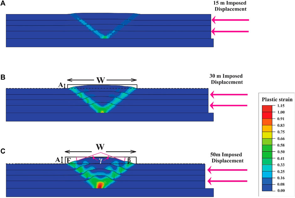
FIGURE 2. The geometry evolution and plastic strain distribution of the detachment fold model; (A) 15 m, (B) 30 m, and (C) 50 m of displacement. Geometric parameters of the fold are; W: fold half-wavelength, A: fold amplitude, γ: interlimb angle.
FIGURE 3. The geometry evolution and plastic strain distribution of the fault-propagation fold model; (A) 20 m, (B) 40 m, and (C) 65 m of displacement. Geometric parameters of the fold are; W: fold half-wavelength, A: fold amplitude, γ: interlimb angle, F: forelimb angle, β: backlimb angle. The white arrow shows the fault slip.
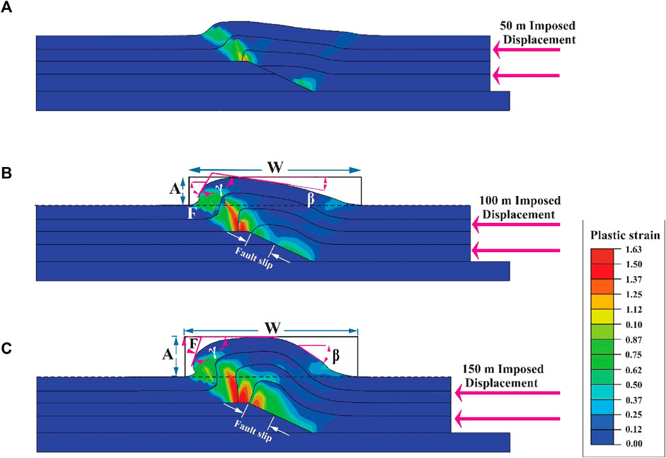
FIGURE 4. The geometry evolution and plastic strain distribution of the fault-bend fold model; (A) 50 m, (B) 100 m, and (C) 150 m of displacement. Geometric parameters of the fold are; W: fold half-wavelength, A: fold amplitude, γ: interlimb angle, F: forelimb angle, β: backlimb angle. The white arrow shows the fault slip.
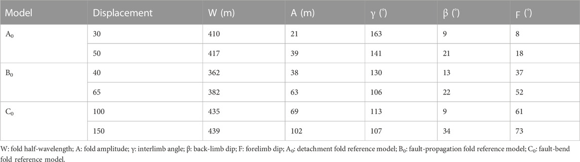
TABLE 2. Geometric parameters of the reference models.
In the detachment fold model, the plastic strain is notably concentrated at the tip of the detachment fault and along the axial surfaces while gradually decreasing towards the crest of the fold (Figure 2). Conversely, in the fault-propagation fold model, the strain exhibits concentration on the fault surface, the fault tip, and the forelimb of the fold (Figure 3). For the fault-bend fold model, the strain concentration is observed on the ramp surface and forelimb, similar to the fault-propagation fold model, albeit with a larger localization area (Figures 3, 4). It is noteworthy that the plastic strain in the fault-propagation fold model surpasses that of the other two models; however, its displacement is comparatively lower than that observed in the fault-bend fold model (Figures 2–4).
Upon comparing the geometric evolution of fault-propagation and fault-bend fold models, it is evident that in the initial stages of folding, the geometry of the fault-bend fold closely resembles that of the fault-propagation fold model until the second layer reaches the top of the ramp. However, when the second layer reaches the top of the ramp, the fold’s crest becomes flattened, leading to the anticipated geometry characteristic of a fault-bend fold (Figures 1–5).
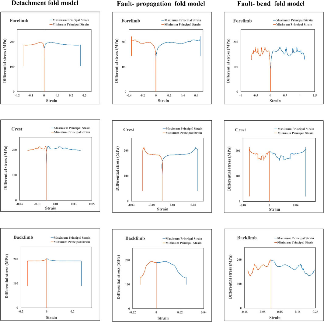
FIGURE 5. Diagrams of differential stress against principal plastic strains at the crest and limbs of the fault-related fold models.
Graphs depicting the differential stress-principal plastic strains are generated for all three reference models of fault-related folds (Figures 5, 6). These diagrams illustrate the variations of two critical parameters that influence the deformation process. The differential stress acts as the driving force behind body deformation, and the plastic strain represents the body’s response to this stress. Notably, the initiation of fold deformation coincides with the commencement of an increase in plastic strains (Figures 5, 6). Moreover, the interval during which the plastic strains remain zero until they begin to rise is referred to as the strain hardening interval. In this phase, the differential stress increases without a corresponding increase in plastic strains. These graphical representations offer valuable insights into the deformation mechanisms and behaviors of the fault-related folds in the respective models.
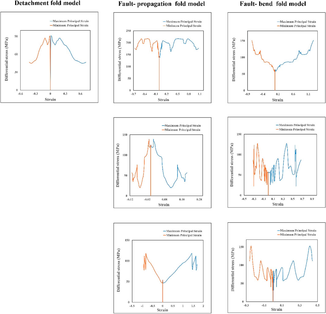
FIGURE 6. Diagram of differential stress against principal plastic strains at the tip (top row), middle (middle row), and base (bottom row) of the fault for fault-related fold models.
Graphical representations of the differential stress-principal plastic strains reveal a consistent increasing-constant-decrease pattern evident in the forelimb, crest, and backlimb of all three models (Figure 5). Notably, during the initial and second steps, as well as the initial stages of the third step of modelling, the differential stress experiences an increment without a simultaneous increase in the principal plastic strains, indicating the occurrence of strain hardening within this interval (Figure 5). This observation is consistent across all three models and highlights the characteristic behavior of the fault-related folds during these specific stages of the folding process. After this stage, strain softening occurs, that is, without increasing the differential stress, the plastic strains increase, and at the end of the modelling, the principal plastic strains are constant, while the differential stress suddenly decreases (Figure 5). This stress-strain pattern is observed in almost all models; only this pattern in the fault-bend fold model is more jagged than in other models (Figure 5). The maximum differential stress in all three models and at all three points of the fold surface (forelimb, backlimb, and crest) is approximately 200 Mpa (Figure 5).
Diagrams of differential stress-principal plastic strains at the fault’s tip, middle, and base in all three models are investigated. Their stress-strain pattern differs from the stress-strain pattern on the fold surface (forelimb, backlimb, and crest) (Figures 5, 6). But on the fault’s surface, a repeating pattern of increase-decrease-increase of the principal plastic strains can be observed against the increase of the differential stress. In all models and all three points on the faults, at the beginning and end of the modelling, the plastic strains increase with the increasing differential stress (Figure 6). In contrast, on the fold’s surface, at the end of the modelling, the differential stress dropped suddenly without changing the plastic strains (Figure 5). Except for the fault tip in the fault-propagation fold model, in all models, the amount of differential stress on the fold surface is higher than on the fault surface. Also, differential stress decreases by moving away from the fault tip (Figure 6).
In the fault-propagation and fault-bend fold models, the determination of fault slip is based on the separation between the second layer and the fault interface (Figures 3, 4). Accordingly, the fault slip gradient diagrams are constructed for these models (Figure 7A). The calculated slip gradients for the fault-propagation and fault-bend fold models are 0.62 and 0.29, respectively. The results indicate a considerable reduction in slip value for the fault-bend fold model compared to the fault-propagation fold model, and this reduction leads to a non-linear slip behavior (Figure 7A). Initially, during the early stages of folding, the slip gradients in these two models exhibit a similar pattern. However, as the third layer traverses the ramp and advances on the upper flat, the width of the plastic strain localization zone expands. Consequently, a portion of the differential stress is allocated to the movement of the third layer on the upper flat, leading to a reduction in the slip magnitude on the ramp (Figures 3, 4, and 7A).
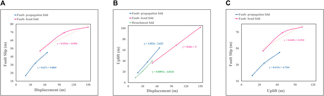
FIGURE 7. (A) The fault slip gradient of the fault-propagation and fault-bend fold models, (B) the uplift gradient of the detachment, fault-propagation, and fault-bend fold models. (C) The diagram of fault slip against the uplift of the fault-propagation and fault-bend fold models.
Furthermore, the uplift gradient of these folds is depicted by considering the variation in fold amplitude, representing the vertical uplift, during the folding process (Figure 7B). The computed uplift gradients for the detachment, fault-propagation, and fault-bend fold models are 0.88, 1.02, and 0.66, respectively (Figure 7B). Consequently, the fault-propagation and fault-bend fold models exhibit the highest and lowest uplift gradients, respectively. This indicates that, in a lithologically similar setting, a fault-propagation fold model would result in the tallest fault-related fold, whereas a fault-bend fold model would lead to the shortest fault-related fold. The disparity in uplift gradients between these models elucidates their distinct abilities to generate variations in height during the folding process.
Also, variations in slip against uplift were investigated for fault-propagation and fault-bend fold models (Figure 7C). The results show the close similarity of slip-uplift diagrams to slip-displacement (slip gradient) diagrams (Figures 7A,C). The reason is the high correlation of uplift-displacement diagrams (uplift gradient) (Figure 7B). Therefore, only the slip and uplift gradient diagrams will be examined in the following.
3.1 The influence of mechanical properties on the slip and uplift gradients
For investigating the role of mechanical properties on slip and uplift gradients, the values of mechanical parameters, including density, Poisson’s ratio, Young’s modulus, cohesion, internal friction angle, and dilation angle, were varied by 20% increment and decrement. Subsequently, the resulting changes in slip and uplift gradients were compared with those of the corresponding reference models (Figures 8–11). The analysis reveals that among the various mechanical properties, only the internal friction angle exerts a significant impact on the uplift gradients of all three fault-related fold types (Figures 8–10). In each case, an increase in the internal friction angle leads to an elevation in the uplift gradient, while a decrease in the angle results in a reduction of the uplift gradient (Figures 8–10).
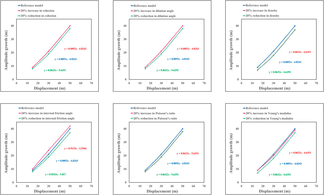
FIGURE 8. The influence of ±20% variation in mechanical properties in the uplift gradient of the detachment fold model.
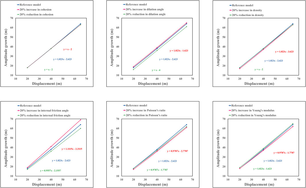
FIGURE 9. The influence of ±20% variation in mechanical properties in the uplift gradient of the fault-propagation fold model.
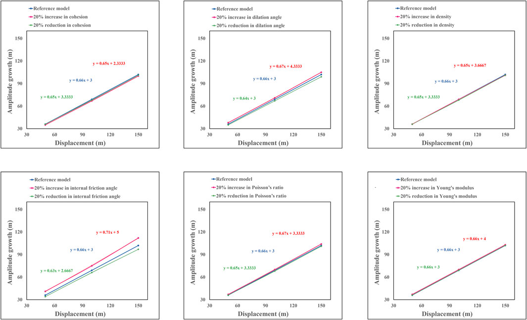
FIGURE 10. The influence of ±20% variation in mechanical properties in the uplift gradient of the fault-bend fold model.
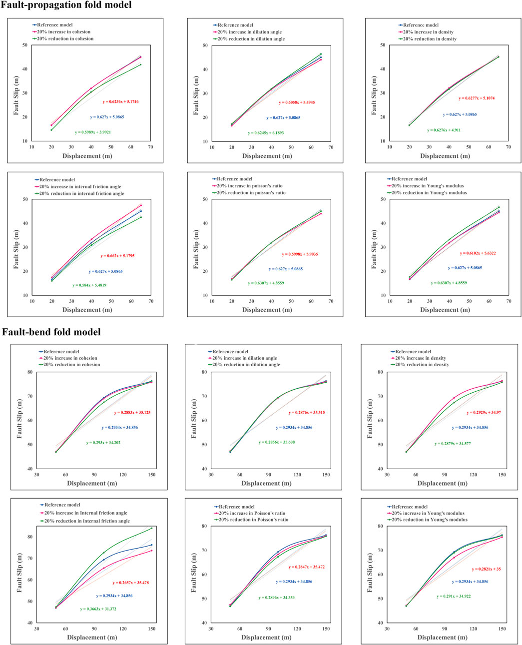
FIGURE 11. The influence of ±20% variation in mechanical properties in the fault slip gradient of the fault-propagation and fault-bend fold models.
Regarding the slip gradient, the internal friction angle demonstrates an influential role in the fault-propagation and fault-bend fold models (Figure 11). In the fault-propagation fold model, an increase in the internal friction angle corresponds to a proportional rise in the fault slip gradient, while a decrease in the angle leads to a decrease in the slip gradient (Figure 11). Conversely, in the fault-bend fold model, an increase in the internal friction angle is associated with a decline in the fault slip gradient, while a reduction in the angle results in an increase in the slip gradient (Figure 11).
Given the significant impact of the internal friction angle on both slip and uplift gradients of fault-related folds, further investigation is conducted to explore its influence on the stress-strain patterns and forelimb thickening of these fold structures.
3.2 Impact of internal friction angle on stress-strain behavior
The investigation extends to examine the impact of varying the internal friction angle on the stress-strain patterns within fault-related folds (Figures 12, 13). To focus solely on folded surfaces, namely, the forelimb, backlimb, and crest, the analysis concentrates on summarizing these changes (Figures 12, 13). The findings reveal that, across all three types of fault-related folds, the stress-strain patterns remain consistent with those observed in the corresponding reference models. Specifically, a ±20% variation in the internal friction angle demonstrates no discernible influence on the stress-strain patterns. However, it is observed that the differential stress in all models and on all folded surfaces exhibits an increase with a rise in the internal friction angle and decreases with its reduction. Notably, in all models, an increase in the internal friction angle leads to a near-constant elevation of differential stress by approximately 50 MPa throughout the folds. Conversely, a decrease in the internal friction angle results in a decline of differential stress by approximately 50 MPa (Figures 5, 12, 13). Additionally, in the fault-bend fold model, the crest experiences an even more pronounced increase in differential stress of nearly 100 MPa, correlating with an increase in the internal friction angle (Figure 12).
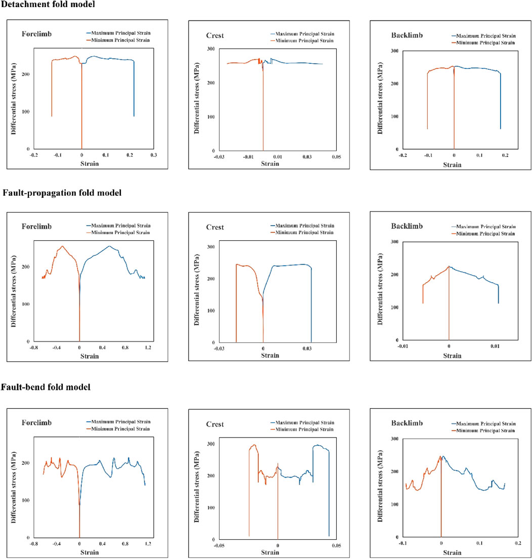
FIGURE 12. The effect of a 20% increase in internal friction angle on the stress-strain pattern of fault-related folds.
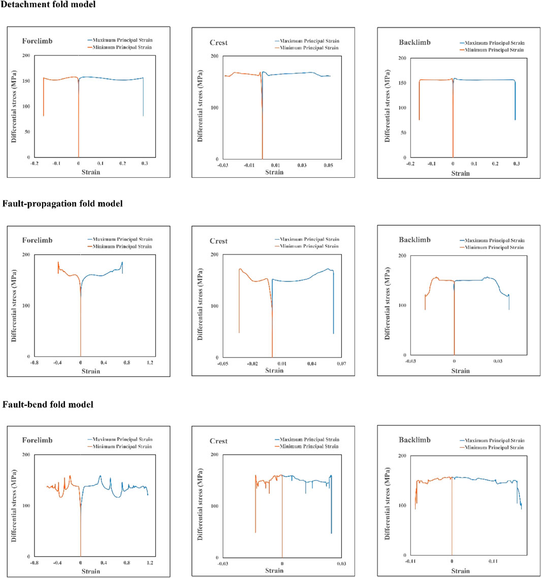
FIGURE 13. The effect of a 20% decrease in internal friction angle on the stress-strain pattern of fault-related folds.
3.3 Impact of internal friction angle on forelimb thickness
An analysis of the results demonstrates that an increased internal friction angle corresponds with a decrease in the interlimb angle across all three fault-related fold models. Conversely, reducing the internal friction angle tends to increase the interlimb angle (Figure 14). To interpret, layers with a higher internal friction angle tend to form tighter folds, whereas layers with lower internal friction angles contribute to the formation of wider or gentler folds (Figure 14). An investigation into the effect of the internal friction angle on the thickness of the forelimb in fault-related fold models reveals that all three detachment fold models, including the reference model (A0) and models with a ±20% change in the internal friction angle (A1 and A2), reside in the no solution zone of the Jamison diagram (Jamison, 1987) (Figure 15A). However, models A1 and A2 are respectively closer to and farther from the solution zone than the reference model (Figure 15A). In the fault-propagation and fault-bend fold models, models B1 and C1, where the internal friction angle increased, are situated in the thinning zone (Figure 15). Conversely, models B2 and C2, where the internal friction angle decreased, are situated in the thickening zone of the Jamison diagram (Jamison, 1987) (Figure 15), with the reference models (B0, C0) occupying the space in between. Furthermore, all three fault-bend fold models are positioned within the mode zone (I) of fault-bend folding, corresponding to the folding style of these models (Figure 15C).
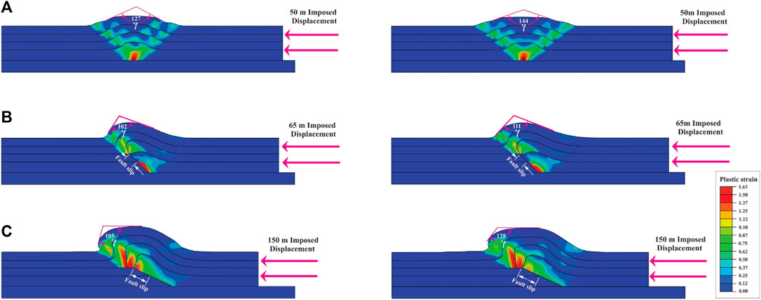
FIGURE 14. The effect of ±20% variation in internal friction angle on the geometry of fault-related fold models, (A) detachment fold model, (B) fault-propagation fold model, and (C) fault bend fold model. The right side shows a 20% decrease in internal friction angle, and the left shows a 20% increase.
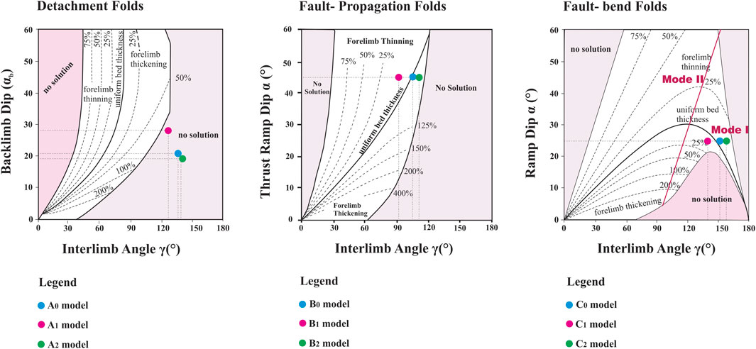
FIGURE 15. The effect of ±20% variation in the internal friction angle on the forelimb thickness of the fault-related fold models. A0, B0, and C0 are reference models; A1, B1, and C1 are models in which the internal friction angle is increased; A2, B2, and C3 are models in which the internal friction angle is decreased.
4 Discussion
This study investigated the role of mechanical properties in the slip and uplift gradients of fault-related folds, deploying a trio of 2D finite element model series as investigative tools. The investigation scrutinized various mechanical properties, including density, Poisson’s ratio, Young’s modulus, internal friction angle, cohesion, and dilation angle. Notably, the results underscored the prominent role of the internal friction angle in determining the slip and uplift gradients of fault-related folds (Figure 11). As a result, an additional evaluation was undertaken to elucidate the impact of the internal friction angle on the stress-strain pattern (Figures 12, 13) and on the thickening of the forelimb (Figure 15).
The findings of this study illustrate that alterations in the internal friction angle do not affect the stress-strain pattern associated with models of fault-related folds. However, an interesting direct correlation between the internal friction angle and differential stress was observed; specifically, an increase in the internal friction angle results in an escalation in differential stress, and conversely, a decrease in the internal friction angle leads to a reduction in differential stress (Figures 12, 13). It is important to note that higher differential stress suggests a potential energy reserve on the surface of the fault. Given that the maximum differential stress is predominantly concentrated at the fault tip within the fault-propagation fold models (Figures 6, 12, 13), it can be inferred that fault-propagation folds that develop within rocks with a higher internal friction angle possess greater seismic power, relative to those with a lower internal friction angle, under equivalent shortening and overburden pressure conditions.
Furthermore, the findings revealed that as the internal friction angle elevates in all three categories of fault-related fold models, there is a corresponding decrease in both the interlimb angle and the thickness of the forelimb. Conversely, a reduction in the internal friction angle produces the inverse effect. This essentially means that with an increasing internal friction angle, a more compressed fold is generated in all three fold types, while a reduction in the internal friction angle yields a broader and gentler fold (Figure 14).
In all three types of fold models, the uplift gradient increases with the increase of the internal friction angle and decreases with its decrease. Results also indicate this parameter’s significant effect on the fault’s slip gradient of fault-propagation and fault-bend fold models (Figure 10). In the fault-propagation fold model, there is a direct relationship between the increase in the internal friction angle and the increase of the fault slip gradient. i.e., with the increase of the internal friction angle, the fault slip gradient increases and decreases with its decrease (Figure 11). This is consistent with our previous results about 3D fault-propagation fold models (Khalifeh-Soltani et al., 2021b). However, in the fault-bend fold model, the opposite prevails. With the rise in the internal friction angle, the fault slip gradient decreases and increases with its decrease (Figure 11). Considering that in both types of folds, the uplift gradient increases with the increase of the internal friction angle, it was expected that the fault slip gradient also increases. However, this expectation was not met in the fault-bend fold model. It was stated earlier that when the third layer passes the ramp tip and moves to the upper flat, the area of the strain distribution on the forelimb increases, and subsequently, the separation of the second layer on the ramp decreases. Since the second layer is an indicator layer for the fault slip, the slip decreases with the reduction of its separation (Figure 11). Therefore, with the increase of the internal friction angle, the amount of slip in the third layer increases, and this layer reaches the ramp tip and moves on the upper flat faster than the reference model. Hence, the process of increase in the strain distribution area on the forelimb occurs earlier than in the reference model. Subsequently, the slip reduction time in the second layer also happens faster than in the reference model. So the amount of slip in this model is reduced compared to the reference model. On the other hand, the early onset of strain distribution at the forelimb causes the amplitude of this model to rise more than the reference model (Figure 14).
All the results show the importance of the internal friction angle in slip and uplift gradients and the stress-strain pattern of the fault-related folds. On the other hand, from a theoretical point of view, the importance of the internal friction angle in controlling and developing deformation in granular materials is undeniable (Khalifeh-Soltani et al., 2023). In granular materials such as rock and soil, failure occurs at the maximum ratio of shear stress to normal stress (τ/σ). In fact, failure occurs due to frictional sliding between materials (Matsuoka, 2014), which is directly dependent on the internal friction angle. Previously, Smart et al. (2012) investigated the developed fault-bend fold (Bargari anticline) in eastern France using 2D finite element modelling and presenting stress-strain diagrams. They studied the role of the dilation angle, cohesion, internal friction angle, overburden pressure, and horse width on this fold’s stress-strain pattern and geometry. They considered the role of several parameters simultaneously. Here, we evaluated the role of each mechanical property separately on slip and uplift gradients for all three end members of fault-related folds. Then the role of the most influential parameter (i.e., internal friction angle) on the forelimb’s thickness is also investigated. Despite these differences, our results are consistent with those they presented (Figures 5, 6, 12, 13). The pattern of stress-strain evolution is similar in both studies (Figures 5 and 6); in addition, in both studies, this pattern is not dependent on the mechanical properties of materials (Figures 5, 6, 12, 13). However, these parameters can change the differential stress values (Figures 5, 6, 12, 13).
As mentioned, the results showed that a tighter fold is created in all three fault-related fold models compared to the reference model with an increased internal friction angle. In contrast, with a decrease in it, a wider and gentler fold is produced (Figure 14). These findings align well with the research conducted by Finch et al. (2002). In their study, which used the discrete element method, they explored the impact of sedimentary cover resilience on the geometry of fault propagation folds. Their conclusions were that incompetent and competent sedimentary covers, respectively, give rise to expansive and restricted deformation zones. A parallel study was carried out by Hardy and Finch (Hardy and Finch, 2006) using discrete element modelling on fault propagation folds, yielding analogous results. They deduced that a frail homogeneous sediment cover leads to a mild monocline, whereas a robust one results in a steep monocline. As such, the conclusions drawn from their research corroborate the outcomes of this study.
The outcomes of the current study on fault-propagation folds align well with our previous research on the same topic (Khalifeh-Soltani et al., 2021b; Khalifeh-Soltani et al., 2021a). The simulation of this fold type in this study is purely to facilitate a more straightforward comparison of the results across the three terminal members of fault-related folds.
4.1 Application of the results for a field example (Ayegan anticline)
Our previous research simulated Ayegan’s fault-related fold in the central Alborz of Iran using the finite element method (Figures 16A,B). Then, we examined the role of overburden pressure, cohesion, dilatation angle, Poisson’s ratio, and Young’s modulus in this model (Khalifeh-Soltani et al., 2021c). Here, we examine the effect of a ±20% variation in internal friction angle on this fold geometry (see (Khalifeh-Soltani et al., 2021c) for geology setting and modelling conditions). The results of the Ayegan model are consistent with other results of this study. An increase in internal friction angle decreases the interlimb angle, while a decrease in internal friction angle increases the interlimb angle. Therefore, the rocks with high internal friction angles create a tighter fold, and those with low internal friction angles make a wider fold (Figures 16C,D).
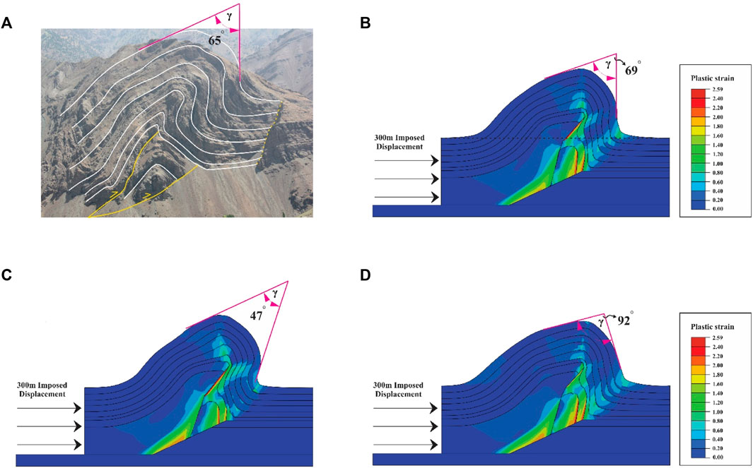
FIGURE 16. (A) the Ayegan anticline in the field, (B) the reference model for the Ayegan anticline (Khalifeh-Soltani et al., 2021c), (C) the Ayegan model in which the angle of internal friction is increased by 20%, and (D) the Ayegan model in which the angle of internal friction is decreased by 20% (γ: interlimb angle).
5 Conclusion
This research utilized the Abaqus™ software (2017) to design three sets of elastic-plastic 2D finite element models, which mimic the end-member behavior of fault-related folds. These models were used to explore the impact of mechanical properties on the formation and evolution of these geological structures.
A clear trend emerged where an increase in displacement led to an amplified limb amplitude and dip across all fault-related fold models, with a concurrent decrease in half-wavelength and interlimb angle. The fault-bend fold model, notably, reflected similar geometry to the fault-propagation fold model until the displacement of the third layer onto the upper flat, which led to the formation of a distinct fault-bend fold geometry.
The distribution of plastic strain varied among the models. In the detachment fold model, the plastic strain was most intense at the detachment fault tip and axial surfaces, diminishing towards the crest. The fault-propagation and fault-bend fold models showed plastic strain concentration primarily on the ramp surface and forelimb, with a more pronounced strain localization zone in the latter.
The study also observed comparable patterns of stress-strain evolution across all three fold models, represented by an increasing-constant-decreasing trend of differential stress against principal plastic strains. The pattern was more complex in the fault-bend fold model.
Differences were found in the slip gradients, with the fault-bend fold model presenting a lower slip gradient compared to the fault-propagation fold model. This was attributed to a wider plastic strain localization zone, causing a reduction in slip on the ramp. In terms of uplift gradients, the fault-propagation and fault-bend fold models had the highest and lowest gradients, respectively, which would translate into different fold heights given similar lithologies.
The internal friction angle emerged as a crucial mechanical property impacting the slip and uplift gradients across all fault-related fold models. Its increase corresponded with an increased uplift gradient, while its decrease showed an inverse relationship. This same trend was observed with slip gradients in the detachment and fault-propagation fold models. However, the relationship was reversed in the fault-bend fold model, where an increase in the internal friction angle led to a decrease in the slip gradient.
The internal friction angle also influenced the interlimb angle and the forelimb thickness. An increase in the internal friction angle led to a decrease in both parameters, indicating the formation of a tighter fold and vice versa.
Considering the seismic potential, differential stress was found to increase with an increase in the internal friction angle, suggesting higher seismic potential in rocks with a high internal friction angle.
Overall, the research offers significant insights into the behavior of fault-related folds and their dependence on mechanical properties. This knowledge can prove vital for assessing hydrocarbon reservoirs and seismic hazards.
Data availability statement
The raw data supporting the conclusions of this article will be made available by the authors, without undue reservation.
Author contributions
Conceptualization, AK-S; methodology, AK-S; software, AK-S; validation, SA and MG; formal analysis, AK-S; investigation, AK-S; resources, RD; data curation, AK-S, SA, and MG.; writing—original draft preparation, AK-S; writing—review and editing, SA, MG, and RD; visualization, AK-S; supervision, SA and MG; project administration, SA and RD; funding acquisition, RD. All authors contributed to the article and approved the submitted version.
Acknowledgments
We are grateful to the reviewers and editors, who provided thorough and insightful reviews that helped improve the paper.
Conflict of interest
The authors declare that the research was conducted in the absence of any commercial or financial relationships that could be construed as a potential conflict of interest.
Publisher’s note
All claims expressed in this article are solely those of the authors and do not necessarily represent those of their affiliated organizations, or those of the publisher, the editors and the reviewers. Any product that may be evaluated in this article, or claim that may be made by its manufacturer, is not guaranteed or endorsed by the publisher.
References
Allmendinger, R. W. (1998). Inverse and forward numerical modeling of tri shear fault propagation folds. Tectonics 17, 640–656. doi:10.1029/98TC01907
Alvarez-Marron, J. (1995). Three-dimensional geometry and interference of fault-bend folds: examples from the ponga unit, variscan belt, NW Spain. J. Struct. Geol. 17, 549–560. doi:10.1016/0191-8141(94)00075-B
Axen, G. J., Lam, P. S., Grove, M., Stockli, D. F., and Hassanzadeh, J. (2001). Exhumation of the west-central Alborz Mountains, Iran, Caspian subsidence, and collision-related tectonics. Geology 29, 559. doi:10.1130/0091-7613(2001)029<0559:EOTWCA>2.0.CO;2
Barani, O. (2012). The effect of lower detachment zone on buckle folds geometry. J. Struct. Eng. Geotechnics 2, 43–47.
Berger, P., and Johnson, A. M. (1980). First-order analysis of deformation of a thrust sheet moving over a ramp. Tectonophysics 70, T9–T24. doi:10.1016/0040-1951(80)90276-0
Brandes, C., and Tanner, D. C. (2014). Fault-Related folding: A review of kinematic models and their application. Earth Sci. Rev. 138, 352–370. doi:10.1016/j.earscirev.2014.06.008
Cook, D. G., and MacLean, B. C. (1999). The Imperial anticline, a fault-bend fold above a bedding-parallel thrust ramp, Northwest Territories, CanadaGeological Survey of Canada contribution no. 1997169. J. Struct. Geol. 21, 215–228. doi:10.1016/S0191-8141(98)00119-9
Cooke, M. L., and Pollard, D. D. (1997). Bedding-plane slip in initial stages of fault-related folding. J. Struct. Geol. 19, 567–581. doi:10.1016/s0191-8141(96)00097-1
Cui, J., Jia, D., Yin, H., Chen, Z., Li, Y., Wang, M., et al. (2020). The influence of a weak upper ductile detachment on the Longmen Shan fold-and-thrust belt (eastern margin of the Tibetan Plateau): insights from sandbox experiments. J. Asian Earth Sci. 198, 104220. doi:10.1016/j.jseaes.2019.104220
Dobson, J. M. M. (1991). The dynamics of foreland fold and-thrust belts, southern Canadian rocky mountains, SW alberta, Canada. Southern Canadian rocky mountains, SW alberta, Canada: Unpublished PhD thesis. Royal Holloway, University of London, 316.
Epard, J. L., and Groshong, R. H. (1995). Kinematic model of detachment folding including limb rotation, fixed hinges and layer-parallel strain. Tectonophysics 247, 85–103. doi:10.1016/0040-1951(94)00266-C
Ferrill, D. A. (1991). Calcite twin widths and intensities as metamorphic indicators in natural low-temperature deformation of limestone. J. Struct. Geol. 13, 667–675. doi:10.1016/0191-8141(91)90029-I
Ferrill, D. A., and Groshong, R. H. (1993). Kinematic model for the curvature of the northern Subalpine Chain, France. J. Struct. Geol. 15, 523–541. doi:10.1016/0191-8141(93)90146-2
Finch, E., Hardy, S., and Gawthorpe, R. (2002). Discrete element modelling of contractional fault-propagation folding above rigid basement fault blocks. J. Struct. Geol. 25, 515–528. doi:10.1016/S0191-8141(02)00053-6
Gan, F., He, B., and Qin, Z. (2020). Hydrological response and soil detachment rate from dip/anti-dip slopes as a function of rock strata dip in karst valley revealed by rainfall simulations. J. Hydrol. (Amst) 581, 124416. doi:10.1016/j.jhydrol.2019.124416
Ghanbarian, M. A., and Derakhshani, R. (2022a). Systematic variations in the deformation intensity in the Zagros hinterland fold-and-thrust belt, Iran. Z. Dtsch. Ges. fur Geowiss. 173, 193–210. doi:10.1127/zdgg/2021/0276
Ghanbarian, M. A., and Derakhshani, R. (2022b). The folds and faults kinematic association in Zagros. Sci. Rep. 12, 8350. doi:10.1038/s41598-022-12337-8
Hansberry, R. L., King, R., Collins, A. S., and Morley, C. K. (2014). Complex structure of an upper-level shale detachment zone: khao Khwang fold and thrust belt, Central Thailand. J. Struct. Geol. 67, 140–153. doi:10.1016/j.jsg.2014.07.016
Hardy, S. (1995). A method for quantifying the kinematics of fault-bend folding. J. Struct. Geol. 17, 1785–1788. doi:10.1016/0191-8141(95)00077-Q
Hardy, S., and Finch, E. (2006). Discrete element modelling of the influence of cover strength on basement-involved fault-propagation folding. Tectonophysics 415, 225–238. doi:10.1016/j.tecto.2006.01.002
Homza, T. X., and Wallace, W. K. (1997). Detachment folds with fixed hinges and variable detachment depth, northeastern Brooks Range, Alaska. J. Struct. Geol. 19, 337–354. doi:10.1016/s0191-8141(96)00118-6
Homza, T. X., and Wallace, W. K. (1995). Geometric and kinematic models for detachment folds with fixed and variable detachment depths. J. Struct. Geol. 17, 575–588. doi:10.1016/0191-8141(94)00077-D
Hughes, A. N., Benesh, N. P., and Shaw, J. H. (2014). Factors that control the development of fault-bend versus fault-propagation folds: insights from mechanical models based on the discrete element method (DEM). J. Struct. Geol. 68, 121–141. doi:10.1016/j.jsg.2014.09.009
Hughes, A. N., and Shaw, J. H. (2015). Insights into the mechanics of fault-propagation folding styles. Bull. Geol. Soc. Am. 127, 1752–1765. doi:10.1130/B31215.1
Jamison, W. R. (1987). Geometric analysis of fold development in overthrust terranes. J. Struct. Geol. 9, 207–219. doi:10.1016/0191-8141(87)90026-5
Jiang, D., Wang, M., Song, G., Yan, B., and Feng, W. (2020). Transition from fault-propagation folds to fault-bend folds determined by along-strike variations of structural styles and fault displacement-distance relationships: the Sumatou anticline, Sichuan Basin, China. J. Struct. Geol. 131, 103951. doi:10.1016/j.jsg.2019.103951
Johnson, A. M., and Berger, P. (1989). Kinematics of fault-bend folding. Eng. Geol. 27, 181–200. doi:10.1016/0013-7952(89)90033-1
Ju, W., Hou, G., and Zhang, B. (2014). Insights into the damage zones in fault-bend folds from geomechanical models and field data. Tectonophysics 610, 182–194. doi:10.1016/j.tecto.2013.11.022
Kent, W. N., and Dasgupta, U. (2004). Structural evolution in response to fold and thrust belt tectonics in northern Assam. A key to hydrocarbon exploration in the Jaipur anticline area. Mar. Pet. Geol. 21, 785–803. doi:10.1016/j.marpetgeo.2003.12.006
Khalifeh-Soltani, A., Alavi, S. A., Ghassemi, M. R., and Ganjiani, M. (2021a). Geomechanical modelling of fault-propagation folds: estimating the influence of the internal friction angle and friction coefficient. Tectonophysics 815, 228992. doi:10.1016/j.tecto.2021.228992
Khalifeh-Soltani, A., Alavi, S. A., Ghassemi, M. R., and Ganjiani, M. (2021b). Influence of ramp geometry and orientation on fault propagation folding: insights from the 3D finite element method. J. Struct. Geol. 153, 104467. doi:10.1016/j.jsg.2021.104467
Khalifeh-Soltani, A., Alavi, S. A., Ghassemi, M. R., and Ganjiani, S. M. (2021c). Influence of mechanical parameters and overburden pressure on the mechanical evolution of fault propagation folds: insights from 2D finite-element elastic-plastic models applied to the Ayegan anticline, central Alborz. Geopersia 11, 101–114. doi:10.22059/GEOPE.2020.297014.648530
Khalifeh-Soltani, A., Ghassemi, M. R., Alavi, S. A., and Ganjiani, M. (2023). Parameters controlling the geometry of detachment and fault-bend folds: insights from 3D finite-element models applied to the Ahwaz anticline in the Dezful Embayment, SW Iran. J. Petroleum Geol. 46, 157–190. doi:10.1111/jpg.12834
Li, Z., Chen, W., Jia, D., Sun, C., Zheng, W., Zhang, P., et al. (2020). The effects of fault geometry and kinematic parameters on 3D fold morphology: insights from 3D geometric models and comparison with the dushanzi anticline, China. Tectonics 39, e2019TC005713. doi:10.1029/2019TC005713
Liu, C., Zhang, Y., and Shi, B. (2009). Geometric and kinematic modeling of detachment folds with growth strata based on Bézier curves. J. Struct. Geol. 31, 260–269. doi:10.1016/j.jsg.2008.11.019
Lutz, B. M., Ketcham, R. A., Axen, G. J., Beyene, M. A., Wells, M. L., van Wijk, J. W., et al. (2021). Thermo-kinematic modeling of detachment-dominated extension, northeastern Death Valley area, USA: implications for mid-crustal thermal-rheological evolution. Tectonophysics 808, 228755. doi:10.1016/j.tecto.2021.228755
Maerten, F., Maerten, L., and Pollard, D. D. (2014). IBem3D, a three-dimensional iterative boundary element method using angular dislocations for modeling geologic structures. Comput. Geosci. 72, 1–17. doi:10.1016/j.cageo.2014.06.007
Maillot, B., and Koyi, H. (2006). Thrust dip and thrust refraction in fault-bend folds: analogue models and theoretical predictions. J. Struct. Geol. 28, 36–49. doi:10.1016/j.jsg.2005.10.001
Matsuoka, H. (2014). The SMP concept-based 3D constitutive models for geomaterials. doi:10.1201/9781482265804
McClay, K. (2011). Introduction to thrust fault-related folding. AAPG Memoir. doi:10.1306/13251330M9450
McClay, K. R. (1995). The geometries and kinematics of inverted fault systems: A review of analogue model studies. Geol. Soc. Spec. Publ. 88, 97–118. doi:10.1144/GSL.SP.1995.088.01.07
Mitra, S. (1990). Fault-Propagation folds: geometry, kinematic evolution, and hydrocarbon traps. Am. Assoc. Pet. Geol. Bull. 74, 921–945. doi:10.1306/0C9B23CB-1710-11D7-8645000102C1865D
Mitra, S. (1993). Geometry and kinematic evolution of inversion structures. Am. Assoc. Petroleum Geol. Bull. 77. doi:10.1306/bdff8e2a-1718-11d7-8645000102c1865d
Morley, C. K., and Jitmahantakul, S. (2020). Secondary detachments within carbonates of the saraburi group, triassic khao khwang fold and thrust belt, Thailand. J. Struct. Geol. 140, 104162. doi:10.1016/j.jsg.2020.104162
Peacock, D. C. P. (2002). Propagation, interaction and linkage in normal fault systems. Earth Sci. Rev. 58, 121–142. doi:10.1016/S0012-8252(01)00085-X
Plotek, B., Guzmán, C., Cristallini, E., and Yagupsky, D. (2021). Analysis of fault bend folding kinematic models and comparison with an analog experiment. J. Struct. Geol. 146, 104316. doi:10.1016/j.jsg.2021.104316
Poblet, J. (2020). Cartographic pattern of terminations of simple, parallel fault-bend folds, fault-propagation folds and detachment folds. J. Struct. Geol. 138, 104135. doi:10.1016/j.jsg.2020.104135
Poblet, J., and McClay, K. (1996). Geometry and kinematics of single-layer detachment folds. Am. Assoc. Petroleum Geol. Bull. 80. doi:10.1306/64ed8ca0-1724-11d7-8645000102c1865d
Poblet, J., McClay, K., Storti, F., and Muñoz, J. A. (1997). Geometries of syntectonic sediments associated with single-layer detachment folds. J. Struct. Geol. 19, 369–381. doi:10.1016/s0191-8141(96)00113-7
Poblet, J., and Stuart, H. (1995). Reverse modelling of detachment folds; application to the Pico del Aguila anticline in the South Central Pyrenees (Spain). J. Struct. Geol. 17, 1707–1724. doi:10.1016/0191-8141(95)00059-M
Qayyum, M., Spratt, D. A., Dixon, J. M., and Lawrence, R. D. (2015). Displacement transfer from fault-bend to fault-propagation fold geometry: an example from the Himalayan thrust front. J. Struct. Geol. 77, 260–276. doi:10.1016/j.jsg.2014.10.010
Rashidi, A., Shafieibafti, S., Nemati, M., Ezati, M., Gholami, E., Mousavi, S. M., et al. (2023). Flexural-slip folding in buckling phases of orogenic belts: insight into the tectonic evolution of fault splays in the East Iran orogen. Front. Earth Sci. (Lausanne) 11, 1169667. doi:10.3389/feart.2023.1169667
Rowan, M. G. (1997). Three-dimensional geometry and evolution of a segmented detachment fold, Mississippi Fan foldbelt, Gulf of Mexico. J. Struct. Geol. 19, 463–480. doi:10.1016/s0191-8141(96)00098-3
Scharer, K. M., Burbank, D. W., Chen, J., Weldon, R. J., Rubin, C., Zhao, R., et al. (2004). Detachment folding in the southwestern tian Shan–tarim foreland, China: shortening estimates and rates. J. Struct. Geol. 26, 2119–2137. doi:10.1016/j.jsg.2004.02.016
Smart, K. J., Ferrill, D. A., Morris, A. P., and McGinnis, R. N. (2012). Geomechanical modeling of stress and strain evolution during contractional fault-related folding. Tectonophysics 576-577, 171–196. doi:10.1016/j.tecto.2012.05.024
Suppe, J. (1983). Geometry and kinematics of fault-bend folding. Am. J. Sci. 283, 684–721. doi:10.2475/ajs.283.7.684
Suppe, J., and Medwedeff, D. A. (1990). Geometry and kinematics of fault-propagation folding. Eclogae Geol. Helvetiae 83.
Vásquez-Serrano, A., Nieto-Samaniego, Á. F., Rangel-Granados, E., Alaníz-Álvarez, S., and Olmos-Moya, M. de J. P. (2021). Architecture of an upper-level weak detachment zone: mexican fold and thrust belt, central Mexico. J. Struct. Geol. 148, 104361. doi:10.1016/j.jsg.2021.104361
Yang, X., Peel, F. J., Sanderson, D. J., and McNeill, L. C. (2017). Episodic growth of fold-thrust belts: insights from finite element modelling. J. Struct. Geol. 102, 113–129. doi:10.1016/j.jsg.2017.07.012
Zanon, M. L., and Gomes, C. J. S. (2019). Sandbox models of fault-bend folding: A new investigation with a pre-existing fault ramp. J. Struct. Geol. 127, 103864. doi:10.1016/j.jsg.2019.103864
Keywords: fault-related folds, geomechanical modelling, stress-strain pattern, the slip and uplift gradients, tectonics
Citation: Khalifeh-Soltani A, Alavi SA, Ghassemi MR and Derakhshani R (2023) Stress and strain evolution in fault-related folds: insights from 2D geomechanical modelling. Front. Earth Sci. 11:1249446. doi: 10.3389/feart.2023.1249446
Received: 28 June 2023; Accepted: 21 August 2023;
Published: 31 August 2023.
Edited by:
Gang Rao, Southwest Petroleum University, ChinaReviewed by:
Zhigang Li, Sun Yat-sen University, Zhuhai Campus, ChinaWei Ju, China University of Mining and Technology, China
Copyright © 2023 Khalifeh-Soltani, Alavi, Ghassemi and Derakhshani. This is an open-access article distributed under the terms of the Creative Commons Attribution License (CC BY). The use, distribution or reproduction in other forums is permitted, provided the original author(s) and the copyright owner(s) are credited and that the original publication in this journal is cited, in accordance with accepted academic practice. No use, distribution or reproduction is permitted which does not comply with these terms.
*Correspondence: Reza Derakhshani, ci5kZXJha2hzaGFuaUB1dS5ubA==