 Riyan Lan1
 Jianyou Lu
 Zilong Zhou
 Lu Chen
- 1Guangxi Xinfazhan Communication Group Co. Ltd., Nanning, Guangxi, China
- 2School of Resources and Safety Engineering, Central South University, Changsha, Hunan, China
- 3College of Civil Engineering, Changsha University of Science and Technology, Changsha, China
Tunnels are commonly excavated using drilling and blasting methods, and the surrounding rock is greatly affected by the vibration of surrounding hole blasting. To study the influence of the number of free surfaces on the energy distribution and attenuation law of surrounding hole blasting vibration signals, on-site experiments and numerical simulation experiments were conducted. The research results indicate that the higher the number of free surfaces, the smaller the peak vibration velocity. The longitudinal Fourier main frequency decreases with the distance from the monitoring point. The more free surface, the greater the centroid frequency and zero crossing frequency. In addition, numerical simulation shows that the degree of rock fragmentation after blasting increases with the increase of the number of free surface of rock.
1 Introduction
As an efficient and economical construction technology, a blasting process is widely applied to mining, basic engineering construction and hydropower engineering (Xia et al., 2018). Nonetheless, only 20%–30% of the energy generated by an explosion can contribute to rock fragmentation, while the rest is dissipated as vibrations, noise, and flying rocks (Trivedi et al., 2014). There is a direct correlation between blasting-induced vibrations and damage to the surrounding structure in these manifestations (Ma et al., 2000; Xia et al., 2013). The researchers mainly describe the blasting-induced vibration through three parameters to establish the relationship it and structural damage, namely, particle peak vibration velocity (PPV), frequency and energy. A convenient measurement, intuitive and easy-to-operate characteristic of PPV makes it a popular criterion for blasting-induced vibration control in practical engineering (Noret et al., 2012). In recent years, researchers have found that it is unreliable to simply use PPV as the criterion of blasting-induced vibration, and the different frequency spectrum structures induced by blasting vibration are also an important cause of structural damage (Aldas, 2010). When the vibration frequency of a structure reaches a certain relationship with its natural frequency, it will cause the amplitude of the structure to amplify, increasing the probability of damage. In general, a structure’s natural frequency is below 10 Hz, so vibration at lower frequencies will cause more structural damage than vibration at higher frequencies (Singh and Roy, 2010). As people’s requirements for blasting vibration control become more and more stringent, two-factor blasting vibration safety criterion based on vibration velocity-frequency has gradually become the mainstream. A detailed understanding of the propagation law of blasting-induced frequency and vibration velocity is a prerequisite for safety evaluation. A blasting vibration’s frequency and velocity depend on many factors (Yilmaz and Unlu, 2013; Qiu et al., 2018; Yang et al., 2019; Peng et al., 2021), including the millisecond time, propagation medium, type of explosive, etc.
Tunnel blasting requires drilling a circle of blast holes along the excavation section, with the spacing of the blast holes matching the minimum load and the depth being the same as the pre advance depth. These holes are called peripheral holes. The significant distinction between smooth blasting and presplit blasting is the order in which the peripheral hole and the main blasting area are detonated. Smooth blasting refers to the blasting that occurs before the peripheral hole is detonated relative to the main blasting area. Otherwise, it is called presplit blasting. According to previous literature, researchers have conducted extensive research on smooth blasting and presplit blasting. Li et al. (2017) reported the smooth blasting technology under the condition of decoupling charge by numerical simulation, the results indicated by using smooth blasting technology, damage to reserved rock can be reduced effectively. An optimized model for smooth blasting parameters has been proposed by Liu and Liu (2017). There has been a comparison between these two blasting techniques from different perspectives by some scholars. From the perspective of contour formation, Lu et al. (2012) compared presplit blasting with smooth blasting. Their research illustrated when the in-site stress is greater than 10∼12 MPa, presplit blasting cannot form contour cracks well. Hu et al. (2014) compared the two blasting techniques from the point of view of over-excavation and under-excavation, and the results demonstrated that Pre splitting blasting is inferior to smooth blasting in terms of effectiveness in excavation profile effect. Zhou et al. (2019) compared the two blasting techniques from the characteristics of blasting-induced vibration. Results showed that smooth blasting produces a vibration signal with a higher PPV and dominant frequencies than presplit blasting. To meet the blasting safety standards, tunnel excavation often uses millisecond delay blasting to reduce the amount of single explosive. It is worth noting that when different detonator sections do are detonated, the blasting of the former section do will usually provide a new free surface for the latter section do to reduce the restriction of the blast hole. In the two different controlled blasting methods of presplit blasting and smooth blasting, the constraint degree of the peripheral holes are different when they are detonated. The rock fragmentation and vibration intensity induced by explosion are significantly affected by the number, location and range of free surfaces. Some researchers have investigated the impact of the number of free surfaces to blasting-induced vibration. In terms of numerical simulation and on-site experiments, Lu et al. (2018) investigated the influence of free surface on blasting-induced PPV. Results stated that the PPV induced by blasting decreases nonlinearly as the number of free surfaces increases. However, through a field test, Uysal et al. (2007) discovered that burden significantly affects blasting-induced vibration and that the velocity of the vibration reduces as burden increases. Blair and Armstrong (2001) conducted a detailed statistical analysis of blast vibration data from a series of stone harvesting fields monitored and the statistical results found that whether the blasthole is constrained or not has no significant effect on the vibration intensity induced by blasting. Through the field test and related numerical simulation analysis, Yang et al. (2016) revealed that when the distance of the measuring point is fixed, the mean frequency induced by blasting decreases with the increase of burden. However, at present, field experimental studies on the impact of the number of free surfaces on the vibration signals and energy distribution rules induced by peripheral hole blasting are insufficient, and the failure mechanism needs further research.
Up to now, blasting vibration’s influence on free surfaces is not well understood.
Compared with the research results of blasting-induced PPV, research on the frequency of blasting-induced vibrations is insufficient. The vibration induced by the peripheral holes have a obvious influence on the rock mass in millisecond delay blasting technique. In this research, the vibration blasting-induced by the peripheral holes in presplit blasting method and smooth blasting method is taken as the research background, and the relationship between the vibration characteristics induced of peripheral holes under different blasting conditions and PPV, frequency and energy is analyzed, and then the potential influence mechanism is further revealed. This study plays a substantial guiding role in blasting parameter optimization and vibration control.
2 Field experiments for the excavation of tunnel
In this section, taking the excavation of a mountain highway tunnel by drilling and blasting as an example, the tunnel excavation is carried out by smooth blasting and presplit blasting, respectively. Moreover, the vibration velocity, frequency and energy distribution induced by peripheral holes blasting are monitored and analyzed, its propagation law is analyzed and summarized.
2.1 Project background
As shown in Figure 1, the site of the field test is selected as a mountain highway tunnel under construction in Guangxi Zhuang Autonomous region. In the double-hole, cross-ridge tunnel, the buried depth is 358.724 m and the design length is 2,791 m. The tunnel’s left and right lines are both long, and the study was conducted on the right line during all on-site tests. The strata in the tunnel area are mainly composed of lower Permian bedrock, mainly composed of moderately weathered limestone, gray-white, cryptocrystalline structure and hard rock.
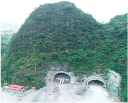
FIGURE 1. The field experiment site.
2.2 Implementation of the field experiments
The step method is used for the tunnel drilling and blasting excavation, and the upper section is tested by the smooth blasting method. To conduct comparative experiments and reduce workload, the peripheral holes at the two waists are set as a separate section. The blasting parameters are arranged as shown in Figures 2A, B, there are 14 blastholes in total, 42 mm is the diameter of the blasthole, the hole spacing of peripheral holes are 0.6 m, all blastholes are filled with 2# rock emulsion explosive, cartridge diameter 32 mm. Decked charge structures are used in axial direction of peripheral holes, and eccentric decoupling charge structure is adopted in the radial direction, the charge structure of the hole is shown in Figure 2C, to ensure accuracy of the test, the industrial digital electronic detonator is used to detonate each hole, and the advance per round is 3 m.
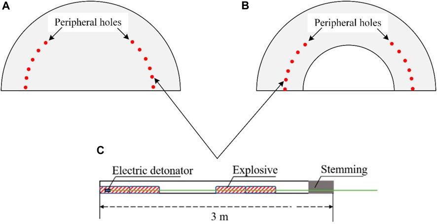
FIGURE 2. Schematic diagram of blast hole arrangement for peripheral hole blasting with different number of free surfaces: (A) number of free surfaces 1, (B) number of free surfaces 2, (C) charge structure of peripheral holes.
To better compare the differences in vibration signals caused by peripheral hole blasting with different number of free surfaces, the layout, geometric shape, charging structure, and initiation method of blast holes with different number of free surfaces are consistent. The portable data acquisition instrument and three-dimensional velocity sensor shown in Figure 3A are used to monitor blasting vibration signals. Figures 3B, C show the on-site physical map of the monitoring location and the layout diagram of the monitoring location, respectively. A total of four monitoring locations have been set, with monitoring locations set at distances of 18, 24, 27, and 30 m from the excavation face. Monitor the blasting vibration velocity in the longitudinal, lateral, and vertical directions.
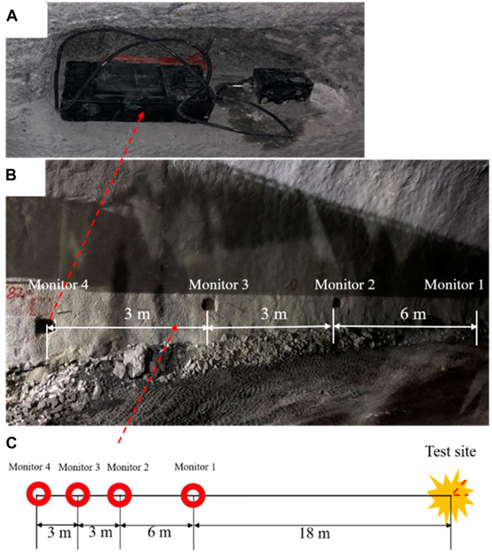
FIGURE 3. Monitoring points implementation scheme: (A) Blasting vibration measurement instrument, (B) Blasting vibration monitoring point, (C) schematic diagram of measuring points.
3 Field experiment results
3.1 PPV analysis
As a general rule, a PPV predictor derived from the United States Bureau of Mines (USBM) can be used to estimate blasting probabilities (Duvall and Fogelson, 1962):
where,
According to above theoretical analysis, the main factors affecting PPV are the explosive amount per delay, the arrangement of blasting parameters, the distance between the monitoring point and the blasting source, and engineering geological conditions. Considering that although the two groups of the tests are conducted in the same tunnel, the geological conditions may not be exactly the same, so allow differences in test results between the two groups. Because the two groups of tests are carried out in two adjacent tunnel excavations, and there is little difference in geological conditions, therefore the influence of geological conditions is ignored. Figure 4 shows the evolution rule of blasting vibration velocity with time monitored at different monitoring positions under different number of free surfaces. According to the signals at different monitoring points, the PPV curves induced by blasting under different number of free surfaces are plotted, as shown in Figure 5. It can be found that regardless of the free surfaces number being 1 or 2, the PPV induced by peripheral hole blasting decreases as the propagation distance increases. It is worth noting that at the same distance from the source of the explosion, the larger the number of free surfaces, the smaller the PPV caused by peripheral hole blasting. This is different from the theoretical analysis results of the PPV prediction formula. The longitudinal PPV caused by peripheral hole blasting with 2 free surfaces is defined as PPV1. The longitudinal PPV generated by peripheral hole blasting with a number of free surfaces of 1 is defined as PPV2. In order to quantitatively analyze the characteristics of longitudinal PPV caused by peripheral hole blasting with different number of free surfaces, the mathematical expression for the amplitude attenuation coefficient P is defined as:
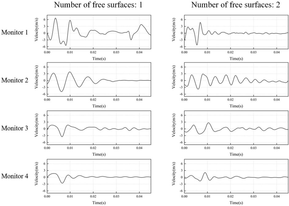
FIGURE 4. A longitudinal velocity-time history of the two sets of blasting tests.
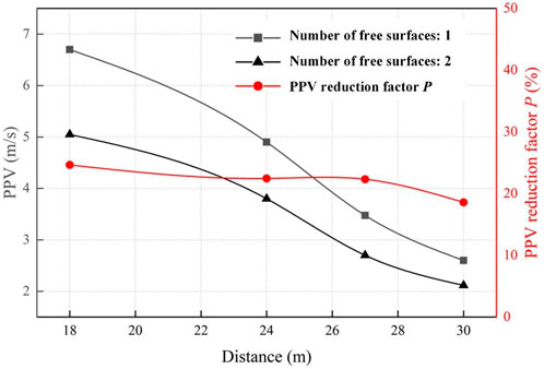
FIGURE 5. Comparison of the PPV-distance curves in the two sets blasting test.
The results show that the longitudinal PPV induced by peripheral hole blasting with 2 free surfaces is significantly lower than that with 1 free surface, with an average amplitude attenuation of 22%.
3.2 Frequency analysis
Another way to evaluate vibration signals besides blasting velocity is to determine the frequency (Yang et al., 2016b). Favreau (1969) proposed a theoretical solution for the phenomenon of elastic waves excited by spherical cavities in elastic media. On this basis, Lu et al. (2013) introduced the expression of vibration velocity spectrum in viscous rock mass during blasting by adding medium damping term:
where
Among them, it is assumed that the triangular blasting load is acting in the elastic cavity, and the blasting load spectrum is as follows:
where
From the expression of blasting vibration velocity spectrum
According to the spectrum analysis of blasting vibration, in general, some characteristic frequencies will be used to describe the main characteristics of the frequency spectrum. This paper mainly describes the spectrum characteristics in three aspects as shown in Figure 6. Dominate frequency, Centroid frequency and Zero-crossing frequency. The blasting vibration signal undergoes Fourier transform to obtain the amplitude spectrum of the vibration velocity, where the frequency corresponding to the maximum amplitude of the vibration velocity amplitude spectrum is the Fourier dominant frequency, and the mathematical expression of the Fourier transform is as follows:
where
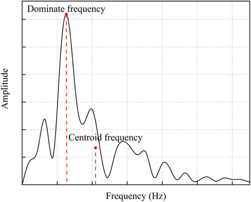
FIGURE 6. Schematic diagram of characteristic frequency definition.
Figure 7 shows the spectrum characteristics generated by peripheral hole blasting with different free surface number. In order to better compare the results of the tests, a ratio of the current amplitude to the maximum amplitude is represented on the Y-axis. But a change in Fourier dominant frequency occurs with an increase in propagation distance, and there is no good linear relationship with the propagation distance, which could not well show the attenuation law of the frequency.
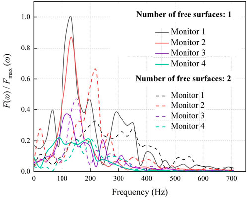
FIGURE 7. Comparing the amplitude-frequency spectra of vibration signals collected at different monitoring sites.
Except to the Fourier dominant frequency, the spectral characteristics can also be described by the Fourier centroid frequency proposed by Trivino et al. (2012). Blasting vibration signals have a centroid frequency that corresponds to the centroid of their velocity amplitude spectrum curves, and the mathematical expression of the centroid frequency is as follows:
where
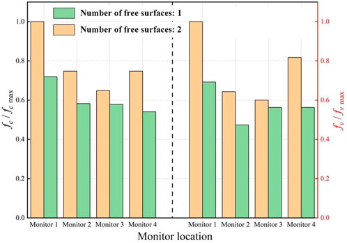
FIGURE 8. Comparisons of the Centroid frequency and the Zero-crossing frequency of vibration signals at different monitoring points.
Both the Fourier centroid frequency and the Fourier dominant frequency need to be calculated to obtain the spectral characteristics, while the value of the Zero-crossing frequency can be directly obtained according to the abscissa of vibration velocity-time curve monitored during blasting. The Zero-crossing frequency is calculated by selecting the time corresponding to velocity-time curve of blasting vibration peak velocity as half a cycle, the Zero-crossing frequency is convenient to calculate and easy to obtain, which is a method for preliminary estimation of blasting vibration frequency. The right half of Figure 8 shows the Zero-crossing frequency of vibration generated by peripheral hole blasting with different number of free surfaces. The mathematical expression is:
where
According to the above test results, the longitudinal Fourier dominant frequency induced by peripheral hole blasting in different numbers of free surfaces decreases with increasing distance from monitoring point, and its centroid frequency and zero-crossing frequency also exhibit a attenuation rule. The smaller the number of free surfaces, the smaller the centroid frequency and zero crossing frequency at the same distance from the explosion source.
3.3 Energy analysis
By analyzing the blasting signal’s PPV and frequency, we can have a clear understanding of the instantaneous change of the blasting signal. The analysis of blasting signal energy can comprehensively evaluate the velocity and duration of blasting signal. In this paper, wavelet transforms are used to analyze the energy of each frequency band of blasting signals. Using wavelet transform, the blasting signal is first decomposed into two components: High-frequency and low-frequency, and then the low frequency part is further decomposed into two parts, and so on. If the blasting signal has frequency 0∼X, it can be decomposed into two parts: 0∼X/2 and X/2∼X high-frequency and low-frequency, and then the low-frequency part 0∼X/2 is continue decomposed into 0∼X/4 and X/4∼X/2 until it is decomposed to a suitable frequency.
After the blasting signal is decomposed in n layers by wavelet transform, calculating the energy coefficient of each reconstructed signal is as follows:
where
Following are the characteristics of energy distribution in different frequency bands under blasting vibration:
where the energy percentage of different frequency bands under blasting vibration is given by
Wavelet transform is used to calculate the energy distribution of blasting signals in different frequency bands, to obtain the best decomposition effect, the appropriate number of decomposition layers and wavelet basis must be determined (Ling and Xi-Bing, 2004). Decomposition layers is determined according to the specific blasting signal and blasting vibration measurement instrument’s minimum working frequency, in this experiment, the signal sampling frequency of the blasting vibration measurement instrument is 4,800 Hz. Nyquist’s sampling theorem states, the highest frequency that can be recorded by this blasting vibration measurement instrument is 2,400 Hz. According to the minimum working frequency of the blasting vibration measurement instrument in this test and avoiding the distortion in the process of decomposition, the decomposition layers number is determined to be 8 layers and the minimum frequency band is 0∼9.77 Hz. Due to the diversity of wavelet basis types, the selection of wavelet basis determines the quality of signal decomposition, the Daubechies’ wavelets have the characteristics of biorthogonality, tight support, approximate symmetry and fast calculation, which makes it effective in blasting signal processing, therefore, according to the characteristics of blasting signal and the requirements of wavelet basis determination, 8th-order Daubechies is used in the previous research.
Taking monitoring point 1 as an example, Figure 9 shows the energy distribution in different longitudinal frequency bands induced by peripheral hole blasting under different free surface number. In the case of 1 free surface, the frequency band of blasting vibration induced by peripheral hole blasting is mainly concentrated in 78.1 Hz–156.3 Hz, accounting for 56.3% of the total energy, and the energy in the 156.3 Hz–312.5 Hz frequency band accounts for 18.5% of the total energy. In the case of 2 free surfaces, the frequency band of blasting vibration induced by peripheral hole blasting is also mainly concentrated in 78.1 Hz–156.3 Hz, accounting for 51.6% of the total energy. The energy in the 78.1 Hz–156.3 Hz frequency band accounts for 4.1% of the total energy, and the energy in the 312.5 Hz–625 Hz frequency band accounts for 39.4% of the total energy. According to the results, the ratio of high-frequency energy induced by peripheral hole blasting with 2 free surfaces is greater than with 1 free surface.
FIGURE 9. The monitoring point 1 percentage of energy distribution in different frequency bands.
Through comparative analysis of test results from the field, this can be found that under the condition that the blasting parameters and geological conditions are approximately the same, the higher the number of free surfaces, the lower the vibration velocity induced by peripheral hole blasting, the higher the vibration frequency, and the higher the proportion of high-frequency vibration energy in the total energy.
When the number of free surfaces is 2, the crushing resistance and movement resistance of the rock mass in the blasting layer are relatively small, which makes it easier for the explosive gas to escape from the cracks and stay in the blast hole for a shorter time, resulting in a decrease in the rise time and duration of pressure on the rock mass. As the working time decreases, the spectrum of blasting load will move towards high frequencies, which naturally leads to high frequency vibration. During the propagation process of blasting induced stress waves, when the stress waves propagate to the free surface, they are reflected as sparse waves that propagate in a reverse direction. The superposition of the reflected waves and the initial stress waves results in a decrease in the intensity of the stress waves, a decrease in the blasting load pressure, and a decrease in the blasting load pressure resulting in a decrease in the induced vibration intensity. Therefore, when the number of free surfaces is 2, the vibration speed is lower than when the number of free surfaces is 1. On the other hand, due to the greater resistance to rock mass breakage and movement when the number of free surfaces is 1, explosive gas is not easy to escape from the cracks. A large amount of explosive gas exists in the blast hole for a long time, and more energy is converted into vibration energy, which can induce higher vibration velocities. The results show that the vibration induced by peripheral hole blasting with a number of free surfaces of 1 is higher than that with a number of free surfaces of 2. In addition, at a certain frequency, the greater the velocity of blasting induced vibration, the greater the damage to the structure. At a certain speed, due to the lower natural frequency of buildings, low-frequency vibration is more likely to cause structural damage. When the number of free surfaces is 2, from the perspective of vibration caused by peripheral hole blasting, it can reduce the vibration speed caused by blasting, move the spectrum structure towards high frequency, and effectively reduce the damage to the structure caused by blasting vibration.
4 Numerical simulation results
As shown in Figure 10, a single hole numerical model was established to analyze the fragmentation effect of rock mass after blasting. Because the blast hole’s length is much larger than its diameter, in order to improve the computational efficiency, a simplified two-dimensional model of plane strain was established, using an uncoupled charge structure with a blast hole diameter of 45 mm and an explosive diameter of 22 mm. The interaction of air, explosives, and rock mass was simulated by combining the Fluid-Structure Interaction algorithm with the Arbitrary Lagrangian-Eulerian method. The number of free surfaces is controlled by setting the boundaries of the rock as free boundary conditions and non reflective boundary conditions. Riedel Hiermaier-Thoma (RHT) model is used as a material model for rock masses in this paper due to its excellent ability to simulate rock fragmentation and fracture using cumulative damage indicators (Wang et al., 2021). For more detailed information on RHT model parameters in this article, refer to references (Xie et al., 2016; Liu et al., 2018; Li et al., 2021).
FIGURE 10. Numerical model.
Figure 11 shows the failure characteristics of rock mass after blasting with different number of free surfaces. Figures 11A–D display the failure characteristics when the number of free surfaces is 1, 2, 3, and 4, respectively. The darker the red color, the more obvious the damage characteristics are. From the research results in Figure 11, it can be found that the rock mass with a free surface has more obvious damage near the free surface after blasting, possibly due to the formation of tensile stress waves after the stress waves generated after blasting are reflected on the free surface, and the tensile strength of the rock is often much smaller than the compressive strength, so the rock is more prone to damage under the action of tensile stress waves. From the research results, it can also be found that with the increase in the number of free surfaces of rock, the degree of fragmentation of rock after blasting increases significantly. Figure 12 shows the number of cracks in rock masses with different number of free surfaces after blasting. It can also be found that the more free surfaces, the more cracks in the rock mass after blasting.
FIGURE 11. The failure characteristics of rock after blasting with different number of free surfaces: (A–D) indicate that the number of free surfaces is 1, 2, 3, and 4 respectively.
FIGURE 12. The number of blasting induced cracks under different number of free surfaces: (A–D) indicate that the number of free surfaces is 1, 2, 3, and 4, respectively.
5 Conclusion
The damage of structures under blasting is directly related to the vibration caused by blasting. A detailed understanding of the propagation law of blasting vibration can better evaluate the harm of blasting vibration. This article studies the propagation law of vibration induced by blasting in the surrounding holes of tunnels with the number of free surfaces through on-site experiments and numerical simulation experiments, and draws the following main conclusions:
(1) The number of free surface has a significant impact on PPV caused by peripheral hole blasting. Under the same blasting parameters and propagation medium, the fewer the number of free surfaces, the higher the PPV caused by peripheral hole blasting.
(2) The number of free surface has a significant influence on the frequency of vibration signals caused by peripheral hole blasting. The smaller the number of free surface, the smaller the centroid frequency and zero crossing frequency.
(3) The number of free surface has a significant impact on the frequency band energy caused by the peripheral hole blasting. The higher the number of free surfaces, the greater the high-frequency energy ratio of peripheral hole blasting.
(4) The number of free surface has a great influence on the degree of rock fragmentation after blasting. With the increase of the number of free surface of rock, the degree of rock fragmentation becomes more obvious after blasting.
Data availability statement
The original contributions presented in the study are included in the article/supplementary material, further inquiries can be directed to the corresponding author.
Author contributions
RL: Project administration, resources. ZW: Writing—original draft, data curation, software. JL: Conceptualization, methodology, writing—review and editing. ZZ: Supervision, funding acquisition, project administration, resources. LC: Investigation. SG: Investigation. All authors contributed to the article and approved the submitted version.
Funding
This work is funded by the National Key Research and Development Program of China (2022YFC2903901), National Natural Science Foundation of China (52274249 and 52104111), the Natural Science Foundation of Hunan (2021JJ30819), Key Laboratory of Advanced Engineering Materials and Structural Mechanical Behavior and Intelligent Control for Universities in Hunan Province (19KA01) and Key Science and Technology Project of Guangxi Transportation Industry (Research on fine blasting and disaster control technology of mountain expressway tunnel) (2020-24).
Acknowledgments
The authors are very grateful to the financial contribution and convey their appreciation for supporting this basic research.
Conflict of interest
Authors RL and SG were employed by Guangxi Xinfazhan Communication Group Co. Ltd.
The remaining authors declare that the research was conducted in the absence of any commercial or financial relationships that could be construed as a potential conflict of interest.
Publisher’s note
All claims expressed in this article are solely those of the authors and do not necessarily represent those of their affiliated organizations, or those of the publisher, the editors and the reviewers. Any product that may be evaluated in this article, or claim that may be made by its manufacturer, is not guaranteed or endorsed by the publisher.
References
Aldas, G. G. U. (2010). Explosive charge mass and peak particle velocity (PPV)-frequency relation in mining blast. J. Geophys. Eng. 7, 223–231. doi:10.1088/1742-2132/7/3/001
Blair, D. P., and Armstrong, L. W. (2001). The influence of burden on blast vibration. Fragblast 5, 108–129. doi:10.1076/frag.5.1.108.3315
Duvall, W. I., and Fogelson, D. E. (1962). Review of criteria for estimating damage to residences from blasting vibration. https://xueshu.baidu.com/usercenter/paper/show?paperid=2af0ef4bf56d48e7057ab5874a8f6936&site=xueshu_se.
Favreau, R. F. (1969). Generation of strain waves in rock by an explosion in a spherical cavity. J. Geophys. Res. 74, 4267–4280. doi:10.1029/JB074i017p04267
Hu, Y., Lu, W., Chen, M., Yan, P., and Yang, J. (2014). Comparison of blast-induced damage between presplit and smooth blasting of high rock slope. Rock Mech. Rock Eng. 47, 1307–1320. doi:10.1007/s00603-013-0475-7
Li, X. P., Huang, J. H., Luo, Y., and Chen, P. P. (2017). A study of smooth wall blasting fracture mechanisms using the Timing Sequence Control Method. Int. J. Rock Mech. Min. Sci. 92, 1–8. doi:10.1016/j.ijrmms.2016.12.001
Li, X., Zhu, Z., Wang, M., Wan, D., Zhou, L., and Liu, R. (2021). Numerical study on the behavior of blasting in deep rock masses. Tunn. Undergr. Space Technol. 113, 103968. doi:10.1016/j.tust.2021.103968
Ling, T. H., and Xi-Bing, L. I. (2004). Laws of energy distribution in different frequency bands for blast vibration signals. J. Central South Univ. Technol. Sci., 310–315.
Liu, K., Li, Q., Wu, C., Li, X., and Li, J. (2018). A study of cut blasting for one-step raise excavation based on numerical simulation and field blast tests. Int. J. Rock Mech. Min. Sci. 109, 91–104. doi:10.1016/j.ijrmms.2018.06.019
Liu, K., and Liu, B. (2017). Optimization of smooth blasting parameters for mountain tunnel construction with specified control indices based on a GA and ISVR coupling algorithm. Tunn. Undergr. Space Technol. 70, 363–374. doi:10.1016/j.tust.2017.09.007
Lu, W., Chen, M., Geng, X., Shu, D., and Zhou, C. (2012). A study of excavation sequence and contour blasting method for underground powerhouses of hydropower stations. Tunn. Undergr. Space Technol. 29, 31–39. doi:10.1016/j.tust.2011.12.008
Lu, W., Leng, Z., Hu, H., Chen, M., and Wang, G. (2018). Experimental and numerical investigation of the effect of blast-generated free surfaces on blasting vibration. Eur. J. Environ. Civ. Eng. 22, 1374–1398. doi:10.1080/19648189.2016.1262285
Lu, W., Zhang, L., Zhou, J., Jin, X., Chen, M., and Yan, P. (2013). Theoretical analysis on decay mechanism and law of blasting vibration frequency. Blasting 30, 1–6+11. doi:10.3963/j.issn.1001-487X.2013.02.001
Ma, G. W., Hao, H., and Zhou, Y. X. (2000). Assessment of structure damage to blasting induced ground motions. Eng. Struct. 22, 1378–1389. doi:10.1016/S0141-0296(99)00072-3
Noret, E., Prod’homme, G., Yalamas, T., Reimeringer, M., Hanus, J.-L., and Duong, D.-H. (2012). Safety of atmospheric storage tanks during accidental explosions. Eur. J. Environ. Civ. Eng. 16, 998–1022. doi:10.1080/19648189.2012.699740
Peng, Y., Liu, G., Wu, L., Zuo, Q., Liu, Y., and Zhang, C. (2021). Comparative study on tunnel blast-induced vibration for the underground cavern group. Environ. Earth Sci. 80, 68. doi:10.1007/s12665-020-09362-z
Qiu, X., Shi, X., Gou, Y., Zhou, J., Chen, H., and Huo, X. (2018). Short-delay blasting with single free surface: Results of experimental tests. Tunn. Undergr. Space Technol. 74, 119–130. doi:10.1016/j.tust.2018.01.014
Singh, P. K., and Roy, M. P. (2010). Damage to surface structures due to blast vibration. Int. J. Rock Mech. Min. Sci. 47, 949–961. doi:10.1016/j.ijrmms.2010.06.010
Trivedi, R., Singh, T. N., and Raina, A. K. (2014). Prediction of blast-induced flyrock in Indian limestone mines using neural networks. J. Rock Mech. Geotechnical Eng. 6, 447–454. doi:10.1016/j.jrmge.2014.07.003
Trivino, L. F., Mohanty, B., and Milkereit, B. (2012). Seismic waveforms from explosive sources located in boreholes and initiated in different directions. J. Appl. Geophys. 87, 81–93. doi:10.1016/j.jappgeo.2012.09.004
Uysal, O., Arpaz, E., and Berber, M. (2007). Studies on the effect of burden width on blast-induced vibration in open-pit mines. Environ. Geol. 53, 643–650. doi:10.1007/s00254-007-0679-9
Wang, H., Wang, Z., Wang, J., Wang, S., Wang, H., Yin, Y., et al. (2021). Effect of confining pressure on damage accumulation of rock under repeated blast loading. Int. J. Impact Eng. 156, 103961. doi:10.1016/j.ijimpeng.2021.103961
Xia, X., Li, H. B., Li, J. C., Liu, B., and Yu, C. (2013). A case study on rock damage prediction and control method for underground tunnels subjected to adjacent excavation blasting. Tunn. Undergr. Space Technol. 35, 1–7. doi:10.1016/j.tust.2012.11.010
Xia, X., Li, H., Liu, Y., and Yu, C. (2018). A case study on the cavity effect of a water tunnel on the ground vibrations induced by excavating blasts. Tunn. Undergr. Space Technol. 71, 292–297. doi:10.1016/j.tust.2017.08.026
Xie, L. X., Lu, W. B., Zhang, Q. B., Jiang, Q. H., Wang, G. H., and Zhao, J. (2016). Damage evolution mechanisms of rock in deep tunnels induced by cut blasting. Tunn. Undergr. Space Technol. 58, 257–270. doi:10.1016/j.tust.2016.06.004
Yang, J., Cai, J., Yao, C., Li, P., Jiang, Q., and Zhou, C. (2019). Comparative study of tunnel blast-induced vibration on tunnel surfaces and inside surrounding rock. Rock Mech. Rock Eng. 52, 4747–4761. doi:10.1007/s00603-019-01875-9
Yang, J. H., Lu, W. B., Jiang, Q. H., Yao, C., and Zhou, C. B. (2016a). Frequency comparison of blast-induced vibration per delay for the full-face millisecond delay blasting in underground opening excavation. Tunn. Undergr. Space Technol. 51, 189–201. doi:10.1016/j.tust.2015.10.036
Yang, J., Lu, W., Jiang, Q., Yao, C., Jiang, S., and Tian, L. (2016b). A study on the vibration frequency of blasting excavation in highly stressed rock masses. Rock Mech. Rock Eng. 49, 2825–2843. doi:10.1007/s00603-016-0964-6
Yilmaz, O., and Unlu, T. (2013). Three dimensional numerical rock damage analysis under blasting load. Tunn. Undergr. Space Technol. 38, 266–278. doi:10.1016/j.tust.2013.07.007
Keywords: tunnel excavation, controlled blasting method, peripheral holes, vibration, free surface
Citation: Lan R, Wang Z, Lu J, Zhou Z, Chen L and Gao S (2023) The influence of the number of free surfaces on the energy distribution and attenuation law of blasting vibration signals from peripheral holes: field experiment and simulation. Front. Earth Sci. 11:1210650. doi: 10.3389/feart.2023.1210650
Received: 23 April 2023; Accepted: 12 June 2023;
Published: 27 June 2023.
Edited by:
Xu Chang, Huaqiao University, ChinaReviewed by:
Kaizong Xia, Chinese Academy of Sciences (CAS), ChinaSong Yang, Liaoning Technical University, China
Copyright © 2023 Lan, Wang, Lu, Zhou, Chen and Gao. This is an open-access article distributed under the terms of the Creative Commons Attribution License (CC BY). The use, distribution or reproduction in other forums is permitted, provided the original author(s) and the copyright owner(s) are credited and that the original publication in this journal is cited, in accordance with accepted academic practice. No use, distribution or reproduction is permitted which does not comply with these terms.
*Correspondence: Jianyou Lu, amlhbnlvdS5sdUBjc3UuZWR1LmNu