 Lianmin Cao
 Ping Yan
95% of researchers rate our articles as excellent or good
Learn more about the work of our research integrity team to safeguard the quality of each article we publish.
Find out more
BRIEF RESEARCH REPORT article
Front. Earth Sci. , 28 December 2023
Sec. Environmental Informatics and Remote Sensing
Volume 11 - 2023 | https://doi.org/10.3389/feart.2023.1180389
This article is part of the Research Topic Advances of Rheological Characteristics of Rock Mass in Deep Mining View all 5 articles
In order to study the effects of stress change and adaptability of the overrun hydraulic stent under impact load, the rigid–flexible coupling numerical model of the stent is established using multi-body dynamics simulation software ADAMS. In the model, the stent is flexibilized using the HyperMesh module, and the column and jack are equivalently replaced with a spring damping system. By applying impact loads to different positions above the front roof beam of the stent, the dynamic response characteristics of the column and the articulation point are obtained at different positions with different strengths. The results show that when the impact load is applied to different positions of the front roof beam, the steady-state response force of the column shows an overall “M" distribution, and along the length direction of the roof beam, the steady-state response force of the column shows an upward trend, and the maximum steady-state response force of the column is 547 kN at point (1, 6); when the impact load is applied to both sides of the front roof beam, the response at the articulation point is greater, resulting in a higher maximum simple harmonic response at that articulation point. When the impact load acts on both sides of the front roof beam, the response of the articulation point is greater, with a maximum simple harmonic response coefficient of 0.75 and a maximum excitation response coefficient of 0.28; when the impact loads of different strengths act on the whole front roof beam, the force acting on the column and pin shaft at the articulation point will produce a large impact, reducing its adaptability. To address this, we can consider changing the top plate stress conditions using methods like high-pressure injection of water and control the gradual and slow release of the top plate stresses. The results of the study provide a reference for the structural strength design and reliability analysis of the hydraulic support, which is of practical significance and value for improving the safe mining of the coal mining face.
Coal is an important basic energy source and industrial raw material in China. With the development of society, the amount of coal mining is increasing, and discovering efficient and safe ways to mine the coal resources has become the focus of attention (Zhang et al., 2017; Kang et al., 2018; Juganda et al., 2020). In the mining process, hydraulic support is one of the key underground support equipment, and the bearing capacity of the support provides a safe working environment for the working face (Verma and Deb, 2013; Xu et al., 2015; Wang et al., 2017; Meng et al., 2021). The underground environment is complicated and changeable, the roof pressure is strong, the strength of the roof plate surrounding the rock in the coal mining roadway is relatively low, and the rock body is relatively loose, which is extremely unfavorable to the maintenance of the roadway. Due to the continuous increase in the depth and intensity of coal mining, various accidents, such as roofing, deformation of the surrounding rock, and destruction of the support, occur from time to time, especially in dangerous working conditions such as cyclic pressure or impact ground pressure, which will pose a greater safety hazard to the underground equipment. In recent years, accidents involving the fracture of support columns caused by impact ground pressure have occurred frequently (Bao, 2020; Long et al., 2018; Pan et al., 2020; Rajwa et al., 2019). Therefore, many scholars have carried out in-depth research on the load-bearing performance of hydraulic support.
Xie et al. (2020) studied the distribution law of bottom plate pressure under different impact conditions of deep well mining filling hydraulic support and found that the bottom plate pressure was in the “V” distribution of front-end subsidence, middle indentation, and back-end warping. Li and Xu (2018) discretized the super-static rock beam into a static single-span beam, analyzed the effects of different parameters such as the stiffness of the overrun bracket, the height of the roadway, and the density of the support on the roadway roof settlement, and strengthened the adaptability of the overrun support system. Szurgacz and Brodny (2019a), Szurgacz and Brodny (2019b), and Szurgacz and Brodny (2020) recorded the state of the column of the hydraulic support in real time, investigated the response characteristics of the column under the impact load, and studied the response characteristics of the column under the impact load based on the method of the roadway section shape test, which was used to study the distribution of specific pressure in the roadway section under the impact load. Test method: the influence of the shape of the roadway section on the hydraulic support was investigated, and the section geometry under actual working conditions was analyzed. The results showed that the deformation of the roadway section may lead to an uneven distribution of the hydraulic support loads. Szurgacz (2022) conducted a dynamic load test on a hydraulic support for longwall mining, which confirmed the possibility of applying the test valve to the developed hydraulic support column control system. Zeng et al. (2022) established a dynamic model of the hydraulic bracket and analyzed the impact response of the top beam and each hinge point. Meanwhile, based on the fluid–solid coupling theory, a bidirectional fluid–solid coupling model of the column was established, and the structural changes of the column and the characteristics of the flow field in the cylinder under the impact load were analyzed. The results showed that the hinges of the front column were more prone to impact damage, and the vortex phenomenon was more prone to both sides of the bottom of the cylinder.
To summarize, impact condition is a common working condition in coal mining, and many scholars have also carried out a lot of research on hydraulic support under impact condition, but mainly on the hydraulic support in the mining area. There is a big difference in the structure of different types of hydraulic support, so there is also a big difference in the response to the impact load. The over-advanced hydraulic support studied in this paper is mainly used in the field of coal mine back-mining roadways, which have a large roof control area compared with ordinary support and can realize the effective support of the roof and reduce the deformation of the coal mining roadway. At the same time, the overrun hydraulic support has strong adaptability, which can well adapt to the changes in the surrounding rock pressure in the working face and achieve a better support effect (Ralston et al., 2014; Prusek et al., 2016; Wan et al., 2017; Reng et al., 2018). Based on the previous research, in order to more accurately obtain the dynamic response characteristics of the overrun hydraulic support under the action of an impact load, a multi-body dynamic model of the overrun hydraulic support is established, and the action of the basic top fracture on the top beam of the support is equated to the impact load. The model is used to analyze the response characteristics of columns and articulation points at different locations and strengths, which provides a reference for the structural design of overrun hydraulic support.
In this paper, a ZH4700/22/30D sliding overrun hydraulic support is taken as the research object. The support is a single telescopic column, the maximum height is 3 m, the initial bracing force is 3880 kN, and the working resistance is 4700 kN. The hydraulic support model is shown in Figure 1. The established 3D model is saved into .X_T format and imported into ADAMS, the stent material is defined as structural steel, the density is 7,850 kg/m3, Young’s modulus is 2.1 × 10⁵MPa, and Poisson’s ratio is 0.3. In order to ensure the accuracy of the model, the stent column of the stent in the model adopts the spring damping system instead of the stent. The stent top beam is set as a collision contact with the top plate, and the base and the earth are fixed. In order to ensure the accuracy of the model, the column of the support is replaced by the spring damping system, and the collision contact between the top beam and the top plate of the support, the fixed contact between the base and the earth, the rotating vice between the front top beam and the rear top beam, the rotating vice between the top beam and the joist, and the ball vice between the joist and the column are all modified. The base is regarded as a rigid body, and the top beam and the joist are treated with flexibility using HyperMesh pre-processing software. Node names are assigned, and the output file “ mnf” is generated to set up the rigid–flexible coupling model.
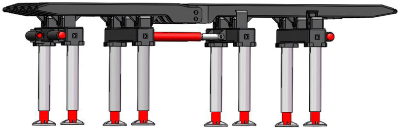
FIGURE 1. Model of ahead hydraulic support.
Before impact simulation of the stent, the active external load of the stent should be determined first, and the active external load is used to simulate the stable working condition of the stent. The actual working resistance of the stent in the underground usually lies between the initial support force and the maximum working resistance; the working resistance of the stent under a certain working condition is selected to be 3,900 kN, and the stent is analyzed. The active external load is applied to the upper surface of the top beam of the stent in a vertical, downward direction. The results are observed, and the contact force between the stent column and the top beam is measured. The steady-state response force between the articulation points of the front–rear top beams and the articulation points between column 1 and front–rear top beam 2 were selected as the research object, and the obtained curves are shown in Figures 2, 3.
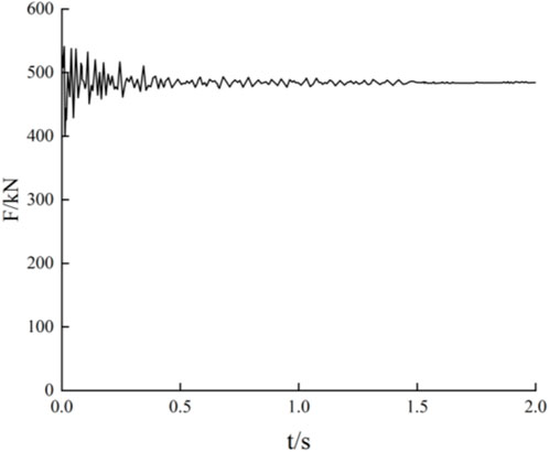
FIGURE 2. Stable working condition of column 1.
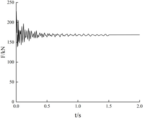
FIGURE 3. Stable working condition of the articulation point of front–rear roof beam 2.
From the figure, it can be seen that under the active external load, the hydraulic stent produces different degrees of vibration and tends to stabilize after 1.5 s. After stabilization, the force on the column is approximately 490 kN, and the force at the articulation point of the front and rear roof beams is approximately 168 kN. From the whole loading results, the force response of the stent is close to that of the actual working conditions, and the static load simulation test is good.
Under the premise that the stent is in stable working condition, in order to accurately analyze the stress condition of the stent when the impact load is applied to the front roof beam, 35 points are taken at equal spacing. The length of the front roof beam is 3,510 mm, the distance between the two points in the Y-direction is 439 mm, the overall width of the stent is 2,800 mm, and the distance between the two points in the X-direction is 525 mm, and 35 points of the impact load are taken uniformly, as shown in Figure 4. According to the coordinate system shown in the figure, the impact load acting points are specified in the X-axis direction, where the load position is defined as (−2, Y) to (2, Y), comprising a total of five groups; in the Y-axis direction, the load position is defined as (X, 1) to (X, 6), comprising a total of seven groups. To facilitate the comparative analysis and taking into account that excessively high impact loads will cause the hydraulic oil in the column cylinder to overflow, thus causing the stent to destabilize during operation, the impact load size is selected to be uniformly 500 kN, and the size of the impact load is determined using the function STEP (time, 2, 0, 2. 02, 500,000).
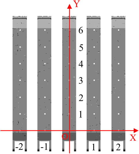
FIGURE 4. Impact load application position.
In the working process of the stent, the pressure from the roof plate is first borne directly by the roof beam and then transferred to the column, which is the main bearing part of the hydraulic stent. It is of great significance to analyze the bearing response of the column.
Figure 5 shows the steady-state response force of column 1 when the impact load is applied to the top beam. As can be seen from the figure, when the front roof beam of the support is subjected to impact load at different locations, the steady-state response force of column 1 shows an “M”-type distribution. When the impact load moves along the positive direction of the X-axis, i.e., the impact load acts at the points (−1, Y) and (1, Y), the force change in column 1 is more obvious. At coordinates (−2, Y), (0, Y), and (2, Y), the response force of the column is basically the same as the steady-state response force under static load. From the direction of the length of the top beam, the steady-state response force of the column shows an increasing trend, and the steady-state response force of the column is the largest at the point (1, 6), which is about 547 kN.
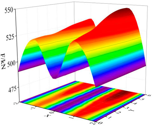
FIGURE 5. Steady-state response force of column 1.
Figure 6 shows the impact response coefficient at the articulation point of front–rear roof beam 2. From the figure, it can be seen that the impact response coefficient of the articulation point of front–rear roof beam 2 is the largest when the impact load is applied to (−1, Y) and when Y is 0, which is approximately 0.75; the impact response coefficient of the articulation point of front–rear roof beam 2 is the largest when the impact load is applied to (1, Y) and when Y is 6, which is approximately 0.70; the impact response coefficient of the articulation point of front–rear roof beam 2 is close to zero when the impact load is applied to the points (−2, Y), (0, Y), and (2, Y), and when Y is changed from 0 to 6, the impact response coefficient is close to 0, indicating that at this time, the impact load has less effect on the force at the articulation point of front–rear roof beam 2.
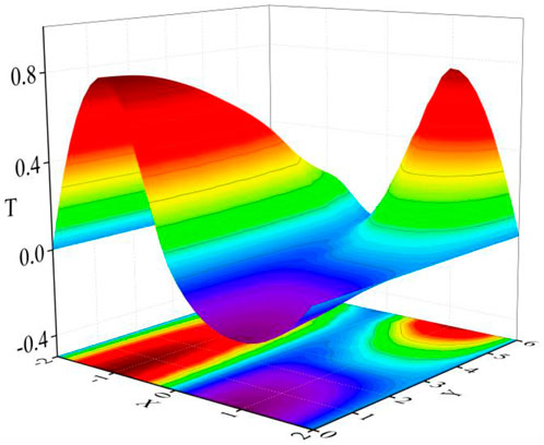
FIGURE 6. Impact response coefficients at the articulation point of front–rear roof beam 2.
Figure 7 shows the excitation response coefficient of the articulation point of front–rear roof beam 2. From the figure, it can be seen that when the impact load acts at the point (−1, Y), the excitation response coefficient along the length direction of the roof beam decreases from 0.22 to 0.1, and when the impact load acts at the point (1, Y), along the length direction of the roof beam, the excitation response coefficient rises from 0.1 to 0.28. From the analysis, it can be seen that when the impact load acts at front roof beam 2, the force fluctuation of the articulation point there is larger and more sensitive, and the pin is more prone to damage. At the front end, the force fluctuation at the articulation point is more significant and sensitive, and the pin is more likely to be damaged.
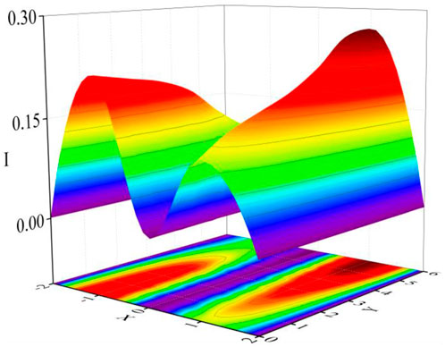
FIGURE 7. Excitation response coefficients at the articulation point of front–rear roof beam 2.
Generally speaking, the step and intensity of the top plate of the return mining roadway coming under pressure will be different in different areas, i.e., the brace may be subjected to impact loads of different intensities at each stage. Therefore, it is necessary to carry out an in-depth study on the impact loads of different intensities on the front roof beam of the stent. Combined with the aforementioned simulation model, the load-acting position is simplified, as shown in Figure 8.
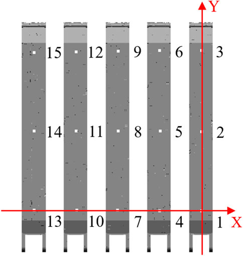
FIGURE 8. Simplified distribution of load action points.
The size of the impact load is set as a single variable using the STEP function to apply the impact load to the upper surface of the front roof beam at 15 locations. The impact load of the impact velocity and other factors remain unchanged, the size of the impact load is set to 500, 750, and 1,000 kN, the impact load is applied to the time of 0.05 s, and the hinged point of column 1 and front–rear roof beam 2 is still taken as a research object.
Figure 9 shows the steady-state response change curve of column 1 under different impact loads. The steady-state response force of column 1 under active external load is 490 kN, and the comparative analysis shows that with the impact load location moving from points 4 to 6, the change in impact load size has a significant effect on the response force of the column, and in the vicinity of the 6 point location, the impact loads are 500, 750, and 1,000 kN. The corresponding steady-state response force of the column is approximately 547, 586, and 640 kN, the maximum difference of which is 93 kN, and the change in the response force of the column at other positions is relatively small. Therefore, the increase in the impact load will lead to the column pressure or tension situation, especially when the impact load acting on the front end of the front roof beam position is too large, which will cause the column to bear a rapid increase in the load, resulting in overflow or damage to the hydraulic column.
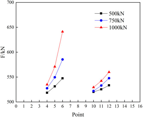
FIGURE 9. Steady-state response force of column 1 under different impact loads.
From Figure 10, it can be seen that when the impact load is applied near point 4, the load is increased from 500 to 1,000 kN. The impact response coefficient is increased from 0.812 to 1.18; i.e., the change in the size of the impact load at this position has a greater impact on the articulation point force. The position of the action is from points 10 to 12, and with the increase of the impact load, the response coefficient increases slowly at first and then increases drastically. From Figure 11, it can be seen that from points 4 to 6, with the increase in the size of the impact load, the excitation response coefficient steadily increases, reaching a maximum value of 0.37 near the position of point 6. However, from points 10 to 12, although the corresponding excitation response coefficient increases, there is an overall downward trend in the process. Therefore, when the impact load is applied to the front end of front roof beams 2 and 4, the articulation point force reaches the impact steady-state force before the large fluctuating change with the increase in the load.
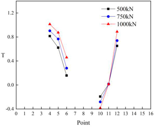
FIGURE 10. Impact response coefficients at the articulation point of front–rear roof beam 2.

FIGURE 11. Excitation response coefficients at the articulation point of front–rear roof beam 2.
In order to ensure the adaptability of the ZH4700/22/30D sliding overrun hydraulic support under impact load, the KJ-216 mine pressure monitoring system is adopted to continuously monitor the working resistance of the sliding overrun support of a coal mine’s 3402 working face back to the roadway, and the structure of the monitoring system is shown in Figure 12.
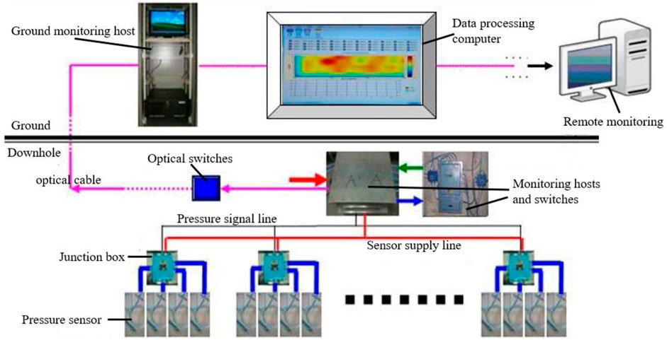
FIGURE 12. Structure of the monitoring system.
The total length of the roadway of the working face is 200 m, which is supported by 26 sliding hydraulic supports. According to the monitoring needs, three monitoring stations are arranged, numbered A, B, and C. The location of the monitoring stations is B in the middle of the roadway and A and C on both sides of the roadway from 7 to 12 m., The three test lines of the monitoring stations are installed in the neighboring three sliding supports in sequence, and the change in different supports in each station is approximately the same, so only the data of one support in each station are analyzed. The changes in different brackets measured by each monitoring station are more or less the same, so only the data of one bracket in each monitoring station are analyzed, and the 6# bracket of A station, 13# bracket of B station, and 20# bracket of C station are randomly selected to retrieve the monitoring data of the brackets in the past 2 months, and the distribution map of the bracket’s working resistance shown in Figures 13–15 is obtained.
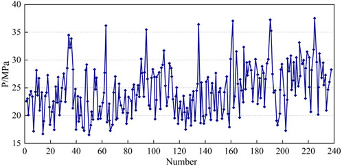
FIGURE 13. Distribution of working resistance of the 6# bracket.
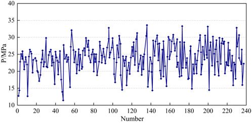
FIGURE 14. Distribution of working resistance of the 13# bracket.
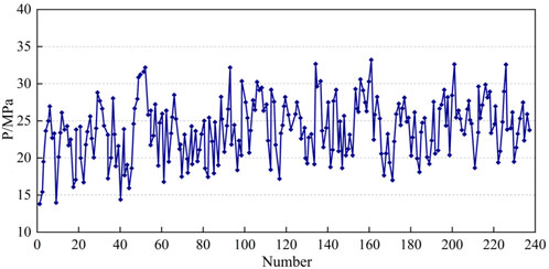
FIGURE 15. Distribution of working resistance of the 20# bracket.
From the working resistance distribution diagram of the sliding type overrun hydraulic support, it can be seen that the roadway roof pressure varies in a wide range, and the maximum working resistance of the support is 37.5 MPa, which is smaller than the maximum working resistance of the support of 38.2 MPa. Through the analysis of the working resistance of the support in the field, it can be seen that the maximum working resistance of the designed sliding-type overrun support can satisfy the requirements of the roadway roof support for 3402 back to the mine and play a stabilizing role for the movement of the rock layer overlying the roadway roof in the process of the support. In the process of support, it plays a stabilizing effect on the movement of the overlying rock layer on the roadway roof.
By analyzing the dynamic response of the column and articulation point of the overrunning hydraulic support under impact load, the following conclusions are drawn:
1) Impact loads acting on different positions of the front roof beam will have different effects on the maximum stresses in the column, and as a whole, it seems safer to be impacted at the front end than at the rear end and safer to be impacted in the center than at the sides.
2) When the impact load acts on both sides of the front roof beam, the response fluctuation of each articulation point is larger, and the degree of impact load on the articulation point of the bracket is significantly higher than that on the column. Therefore, in the process of optimizing the design of the bracket, it is essential to meet not only the load-bearing requirements of the column but also those of the pin.
3) When the top plate pressure increases to a certain value, the overall impact on the hydraulic bracket column and each articulation of the pin axis of the force is larger, which will reduce its adaptability to dynamic loads. Therefore, we can consider changing the top plate stress conditions through methods such as high-pressure water injection to control the gradual and slow release of the top plate stress.
4) Through the field test, it can be seen that the average working resistance of the sliding-type overrun hydraulic support is 37.5 Mpa, which does not exceed the maximum working resistance of the support. This level of resistance meets the requirements for supporting the top plate of the roadway and stabilizes the movement of the rock layer overlying the top plate of the roadway during the support process.
The original contributions presented in the study are included in the article/Supplementary Material; further inquiries can be directed to the corresponding author.
All authors listed made a substantial, direct, and intellectual contribution to the work and approved it for publication.
The authors declare that the research was conducted in the absence of any commercial or financial relationships that could be construed as a potential conflict of interest.
All claims expressed in this article are solely those of the authors and do not necessarily represent those of their affiliated organizations, or those of the publisher, the editors, and the reviewers. Any product that may be evaluated in this article, or claim that may be made by its manufacturer, is not guaranteed or endorsed by the publisher.
Bao, Y. (2020). Study on key technology of intelligent control in fully-mechanized top coal caving face in extra thick seam. Coal Sci. Technol. 48 (7), 55–61. doi:10.13199/j.cnki.cst.2020.07.004
Juganda, A., Strebinger, C., Brune, J. F., and Bogin, G. E. (2020). Discrete modeling of a longwall coal mine gob for CFD simulation. Int. J. Min. Sci. Tech. 30 (4), 463–469. doi:10.1016/j.ijmst.2020.05.004
Kang, H., Wang, G., Jiang, P., Wang, J., Zhang, N., Jing, H., et al. (2018). Conception for strata control and intelligent mining technology in deep coal mines with depth more than 1 000 m. J. China Coal Soc. 43 (7), 1789–1800. doi:10.13225/j.cnki.jccs.2018.0634
Li, D., and Xu, Y. (2018). Study on bearing behavior of advanced hydraulic support along woring face strike. Coal Min. 23 (01), 5–7+50. doi:10.13532/j.cnki.cn11-3677/td.2018.01.002
Long, X., Turgun, A., Yue, R., Ma, Y., and Luo, H. (2018). Influence factors analysis of RC beams under falling weight impact based on HJC model. Shock Vib. 2018. doi:10.1155/2018/4731863
Meng, Z. S., Zhang, J. M., Xie, Y. Y., Lu, Z. G., and Zeng, Q. L. (2021). Analysis of the force response of a double-canopy hydraulic support under impact loads. Int. J. Simul. Model. 20 (4), 766–777. doi:10.2507/ijsimm20-4-co18
Pan, J., Qi, Q., Liu, S., Wang, S., Ma, W., Kang, X., et al. (2020). Characteristics,types and prevention and control technology of rock burst in deep coal mining in China. J. China Coal Soc. 45 (1), 111–121. doi:10.13225/j.cnki.jccs.YG19.1638
Prusek, S., Plonka, M., and Walentek, A. (2016). Applying the ground reaction curve concept to the assessment of shield support performance in longwall faces. Arabian J. Geosciences 9 (3), 167. doi:10.1007/s12517-015-2171-2
Rajwa, S., Janoszek, T., and Prusek, S. (2019). Influence of canopy ratio of powered roof support on longwall working stability - a case study. Int. J. Min. Sci. Tech. 29 (4), 591–598. doi:10.1016/j.ijmst.2019.06.002
Ralston, J., Reid, D., Hargrave, C., and Hainsworth, D. (2014). Sensing for advancing mining automation capability: a review of underground automation technology development. Int. J. Min. Sci. Technol. 24 (3), 305–310. doi:10.1016/j.ijmst.2014.03.003
Reng, H., Yi, B., and Gang, H. (2018). Self adaptive support control method of hydraulic support-surrounding rock in fully-mechanized coal mining face. Coal Sci. Technol. 46 (01), 150–155. doi:10.13199/j.cnki.cst.2018.01.021
Szurgacz, D., and Brodny, J. (2019a). Analysis of the influence of dynamic load on the work parameters of a powered roof support's hydraulic leg. Sustainability 11 (9). doi:10.3390/su11092570
Szurgacz, D., and Brodny, J. (2019b). Tests of geometry of the powered roof support section. Energies 12 (20). doi:10.3390/en12203945
Szurgacz, D., and Brodny, J. (2020). Adapting the powered roof support to diverse mining and geological conditions. Energies 13 (2). doi:10.3390/en13020405
Szurgacz, D. (2022). Analysis of the pressure increase in the hydraulic cylinder of the longwall powered roof support during use. Appl. Sciences-Basel 12 (17). doi:10.3390/app12178806
Verma, A. K., and Deb, D. (2013). Numerical analysis of an interaction between hydraulic-powered support and surrounding rock strata. Int. J. Geomech. 13 (2), 181–192. doi:10.1061/(asce)gm.1943-5622.0000190
Wan, L., Liu, P., Meng, Z., and Lu, Y. (2017). Analysis of the influence of impact load on shield beam of hydraulic support. J. China Coal Soc. 42 (9), 2462–2467. doi:10.13225/j.cnki.jccs.2016.1778
Wang, G., Pang, Y., Li, M., Ma, Y., and Liu, X. (2017). Hydraulic support and coal wall coupling relationship in ultra large height mining face. J. China Coal Soc. 42 (2), 518–526. doi:10.13225/j.cnki.jccs.2016.0699
Xie, Y., Meng, Z., Zeng, Q., Yang, C., and Gao, K. (2020). Analysis of distribution characteristics of study on floor specific pressure of hydraulic support for deep mining based on impact loading. J. China Coal Soc. 45 (3), 982–989. doi:10.13225/j.cnki.jccs.SJ19.1541
Xu, Y., Wang, G., and Ren, H. (2015). Theory of coupling relationship between surrounding rocks and powered support. J. China Coal Soc. 40 (11), 2528–2533. doi:10.13225/j.cnki.jccs.2015.7023
Zeng, Q., Li, Z., Wan, L., Ma, D., and Wang, J. (2022). Research on dynamic characteristics of canopy and column of hydraulic support under impact load. Energies 15 (13), 4638. doi:10.3390/en15134638
Keywords: overhead hydraulic support, impact load, rigid–flexible coupling model, stress variation, dynamic response
Citation: Cao L, Yan P, Xi W, Zhang X, Jin X and Yang H (2023) Study on the bearing characteristics of overrun hydraulic support under impact loading. Front. Earth Sci. 11:1180389. doi: 10.3389/feart.2023.1180389
Received: 06 March 2023; Accepted: 31 October 2023;
Published: 28 December 2023.
Edited by:
Peng Huang, China University of Mining and Technology, ChinaReviewed by:
Yu Liu, Jiangsu Normal University, ChinaCopyright © 2023 Cao, Yan, Xi, Zhang, Jin and Yang. This is an open-access article distributed under the terms of the Creative Commons Attribution License (CC BY). The use, distribution or reproduction in other forums is permitted, provided the original author(s) and the copyright owner(s) are credited and that the original publication in this journal is cited, in accordance with accepted academic practice. No use, distribution or reproduction is permitted which does not comply with these terms.
*Correspondence: Hongjuan Yang, c2tkOTkxMDk0QHNkdXN0LmVkdS5jbg==
Disclaimer: All claims expressed in this article are solely those of the authors and do not necessarily represent those of their affiliated organizations, or those of the publisher, the editors and the reviewers. Any product that may be evaluated in this article or claim that may be made by its manufacturer is not guaranteed or endorsed by the publisher.
Research integrity at Frontiers
Learn more about the work of our research integrity team to safeguard the quality of each article we publish.