 Yuesong Bai1,2
 Yongxiang Zheng
94% of researchers rate our articles as excellent or good
Learn more about the work of our research integrity team to safeguard the quality of each article we publish.
Find out more
ORIGINAL RESEARCH article
Front. Earth Sci., 16 March 2023
Sec. Environmental Informatics and Remote Sensing
Volume 11 - 2023 | https://doi.org/10.3389/feart.2023.1163295
This article is part of the Research TopicAdvances in Fluid-Solid Coupling Processes between Fractures and Porous Rocks: Experimental and Numerical InvestigationView all 11 articles
The failure types of bedding determine the penetration behavior of hydraulic fracture. A stratum model containing bedding was established based on the 3D block distinct element method to explore the penetration behavior of hydraulic fractures with different types of bedding. The mechanics of hydraulic fractures penetrating the shear- failure bedding plane and tensile-failure bedding plane were analyzed. The results showed that the shear-failure bedding plane was more difficult to expand than the tensile-failure bedding plane after the hydraulic fracture turns to bedding plane. The initial stress magnitude controls the expansion difficulty of hydraulic fractures, and the high stress magnitude attenuated penetration behavior. The vertical stress affected the shear failure by increasing the shear strength of the bedding plane. It affected the tensile failure by increasing the initiation stress of the bedding plane. The effect of horizontal stress on the penetration behavior included the influence on the initiation stress of vertical joints and the enhancement of the interference stress on the horizontal bedding plane. The conclusions can provide the guidance for hydraulic fracturing in reservoir with bedding planes.
Bedding planes is widely developed in shale. The penetration behavior of hydraulic fractures refers to the behavior of whether hydraulic fractures can cross the bedding plane. It has an important influence on the network of hydraulic fractures (Zhang et al., 2019; Huang et al., 2020; Tan et al., 2020). If the hydraulic fracture cannot cross the bedding plane, the fracture height is limited. Conversely, if the hydraulic fractures can cross the bedding plane, the hydraulic fracture can connect multiple layers (Tong et al., 2020). The complexity of fracture network requires both fracture height and multiple fracturing (Shicheng et al., 2021). Consequently, it is meaningful to explore the influence of the bedding plane on the formation of fracture network (Xiao et al., 2019).
Previous studies largely focused on the influence factors of penetration behavior of hydraulic fracture. The influence factors can be divided into three types, the stress difference (Warpinski et al., 1982; Huang et al., 2016; Weng et al., 2018), the difference of rock properties (Huang et al., 2018; Xu et al., 2019; Huang et al., 2023), and the weak bedding planes (Tang and Wu, 2018; Xing et al., 2018; Zhang et al., 2022). Some numerical simulation and physical experiments about the penetration behavior of hydraulic fractures showed that the filtration of fracturing fluid into the bedding plane reduces the penetration ability (Ji et al., 2015; Huang et al., 2019; Gao and Ahmad, 2020; Luo et al., 2022). It mainly describes the phenomenon that the bedding planes hindered fracture propagation, but fails to explain the control mechanism of bedding on hydraulic fracture. Actually, the penetration behavior of hydraulic fractures is mainly related to the mechanical behavior of the weak bedding plane. Heng et al. (2021) believe that the penetration behavior of hydraulic fractures is controlled by the mechanical properties of the bedding joint and the local stress state of the fracture tip. And the penetration behavior of hydraulic fractures is a path selection problem. It means that the hydraulic fractures usually propagate along the path with the least resistance. Zhang et al. (2021a) and Zhang et al. (2021b) believe that the stress disturbance induced by weak plane before hydraulic fractures approach the weak bedding plane results in the energy dissipation on the bedding plane. Huang et al. (2022) analyzed the penetration law in the layered rock mass under different regimes based on the particle distinct element method. Zheng et al. (2019) and Zheng et al. (2022) analyzed the evolution of normal stress and shear stress on the bedding plane when the hydraulic fracture approached through the block distinct element method, and identified the discontinuous deformation (slip or shear failure) at the fracture tip as the main reason why the hydraulic fracture could not cross the bedding. Wang et al. (2019) also showed that the increase of shear stress on the bedding plane and the passivation of fracture tip affect the penetration of hydraulic fractures. Tan et al. (2021) proposed the notion of transition zone in the layered formation and investigated the effects of multiple influencing factors on hydraulic fracture vertical propagation behavior based on XFEM-based CZM method. Zhao et al. (2022) given a new pseudo 3D hydraulic fracture propagation model for sandstone reservoirs considering fracture penetrating height. In conclusion, the mechanism of weak bedding plane hindering vertical propagation of fractures has been preliminarily understood, that is, the shear behavior on the bedding plane increases the difficulty of hydraulic fracture penetration. Therefore, the penetration behavior of hydraulic fractures can be determined by stress state at connection point between hydraulic fracture and bedding plane.
The stress state in the formation determines the choice of the path after the hydraulic fracture meets the bedding plane. If the stress field meets the failure criterion of the bedding plane first, the bedding planes open and the hydraulic fracture turns to spread along the bedding plane. If the stress filed meets the failure criterion of the fracture tip, the fractures propagate along the original path and cross the bedding plane. Therefore, the strength of the bedding plane plays an important role in fracture penetration. According to the strength characteristics, the bedding plane can be divided into two categories. They are shear-failure bedding plane (the shear strength of the bedding plane is low) and tensile-failure bedding plane (the tensile strength of bedding plane is low). However, the existing researches mainly focus on the shear failure of bedding plane. There are few discussions about the failure types of bedding plane and penetration behavior of fracture.
Here, the penetration behavior of hydraulic fractures is calculated by the 3D block distinct element method (3D DEM) considering the failure type of bedding plane and in-situ stress conditions. The influence of stress filed on fracture propagation path under different failure types of bedding plane was analyzed. The structure of this paper is as follow. Firstly, the 3D DEM is introduced and the block model with bedding plane is established. Then, the stress evolution of fracture penetration behavior in shear-failure bedding plane is studied. Finally, the stress evolution of fracture penetration behavior in tensile-failure bedding plane is analyzed. In conclusion, this paper analyzes the influence mechanism of bedding failure type and stress state on the penetration behavior of hydraulic fractures, which has important theoretical guiding significance for the hydraulic fracturing construction of layered rock mass.
The block distinct element method has an advantage in simulating the hydro-mechanic coupling behavior in the fracture. In this paper, the block distinct element method was used to simulate the hydraulic fracturing. The block distinct element describes the discontinuity by a set of distinct blocks. So, it has significant advantages in modeling discontinuities. Each block is subdivided into finite difference elements consisting of tetrahedral regions and nodes. The velocities, displacements and joint forces of all nodes at different time steps follow the Newton’s laws of motion. The discontinuity is expressed by the boundary between blocks. The 3D DEM have been used by Zheng. See literature (Zheng et al., 2019; Zheng et al., 2022) for details about the validation of this method.
(1) The failure of joints
The failure of the joint represents the opening of the fracture. In the block distinct element method, joints are described by contacts. The constitutive model of joint is the Coulomb slip joint model. This model considers shear failure, tensile failure and dilation. During the elastic stage, the contact is described by the normal stiffness and tangential stiffness. The normal behavior of the joint can be expressed as (Tang and Wu, 2018)
The shear behavior can be expressed as:
Where, Ac is the area of contact. ΔFn is the increment of normal force, ΔFis is the shear stress increment, Kn is the normal stiffness, Ks is tangential stiffness, ΔUn is the normal displacement increment, ΔUis is tangential displacement increment.
The maximum normal tensile force of the joint (without slip or cracking) is:
Where, T is the tensile strength.
The maximum shear force allowed by the joint is:
Where, c is the cohesion of the joint and φ is the friction angle.
The contact fails when the stress on the joint equals to its tensile or shear strength. Then the tensile strength and cohesion of the joint equals to zero after failure. Here, the maximum tensile and shear force on the joint plane can be expressed as:
The instantaneous loss of strength after failure is the “displacement-weaken” behavior of joint plane. Here, the new contact force between the blocks will be updated (assume that the compression is positive). For tensile failure, the update mode of contact force is:
If
For shear failure, the update mode of the contact force is:
If
Where, the shear force is
Shear dilation occurs only in the slip mode. Then, the shear displacement increment can be expressed as:
The shear displacement causes the change in normal displacement considering dilation. The relationship can be characterized by the dilation angle ψ. And their relationship is:
Where, ΔUn(dil) is normal displacement considering dilation. Ψ is the dilation angle.
Here, the influence of dilation should be considered in the normal force, and the normal force becomes:
(2) Fluid flow in joints
The fluid flow in the joint follows to the Navier-Stokes equation. When the joint surfaces are approximately parallel non-permeable and the fluid is incompressible, the Navier-Stokes equation can be simplified to the Reynolds equation.
where u= u(xi) is the distance of the two non-permeable surfaces at a point xi on the plane. ϕ, ρ and μ are the head height, fluid density, and fluid viscosity, respectively.
Where, the permeability of a single fracture is u2/12, and the hydraulic conductivity is
The essence of the fracture height containment is the interaction between the hydraulic fracture and bedding plane. In order to reveal the behavior of hydraulic fractures before and after encountering bedding, a base model of bedding stratum (shown in Figure 1) is established. The size of model is 1 m*1 m*1 m. It contains two horizontal joints and one vertical joint (shown in Figure 1B). Among them, the vertical joint is set to simulate the preset hydraulic fracture, while the horizontal joints are set to simulate the horizontal bedding plane. The distance between two horizontal joints is 0.3 m. The injection point is located between two bedding planes. Based on the established model, different injection rates and fracturing fluid viscosities can be set according to the experiment plan.
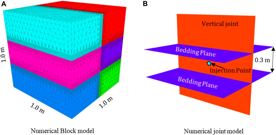
FIGURE 1. Stratum and joint model. (A) Numerical block model. (B) Numerical joint model.
We focus on the influence of failure type of bedding plane and in-situ stress on the penetration behavior of hydraulic fractures. The failure type can be divided into shear failure and tensile failure. The shear-failure bedding plane always has the high tensile strength and low shear strength. Therefore, the shear failure is the main type when the hydraulic fracturing approaches bedding plane. The tensile failure bedding plane always has the high shear strength and low tensile strength. So, the tensile failure is the main failure type. According to their types, the parameters for the shear-failure bedding plane and tensile-failure bedding plane are list in Table 1.
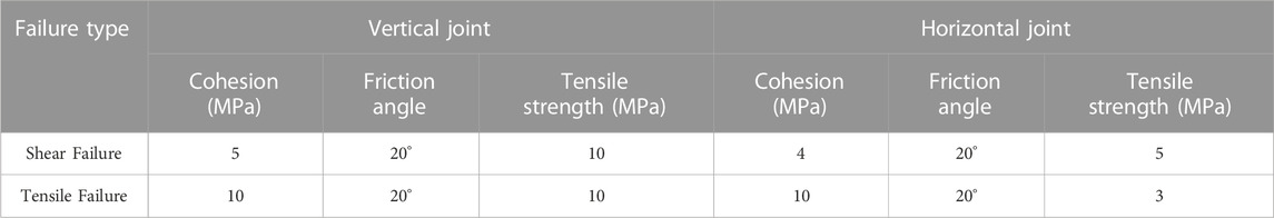
TABLE 1. Base parameters for two types of bedding planes.
In addition to the failure type, the in-situ stress is also of great importance. The stress includes the magnitude and difference of the initial in-situ stress. Consequently, the effects of the stress magnitude and difference are discussed separately with two types of failure. The influence mechanism of horizontal stress and vertical stress variation is also discussed in detail.
Other parameters are set according to the laboratory data and previous literatures. The rock density is 2,600 kg/m3. The rock elastic modulus is 20 × 103 MPa. The pore pressure is 1 MPa. And the Poisson’s ratio is 0.25.
No matter how the fracture propagates, the hydraulic fracture will eventually encounter the bedding plane at the intersection of the horizontal bedding and vertical joints. Then, the fracture chooses propagation path according to the stress state and strength of the horizontal and vertical joints. So, the stress state is of great significance for the penetration behavior. In order to investigate the stress state before and after the hydraulic fracture meeting the intersection, the different stress states of the vertical joints and horizontal joints at the intersection of the hydraulic fracture in the model are extracted. The details are shown in Figure 2 (Zheng et al., 2022). The solid black line in the figure represents the hydraulic fracture, and the dashed blue line indicates the location of the horizontal bedding plane. Here, the hydraulic fracture has reached but not yet crosses the bedding plane. Next, the hydraulic fracture will continue to expand, it may pass through the bedding plane or be captured by the bedding plane. The right-hand picture in Figure 2 gives the connection between different elements. If the connections (block1 and block3, or block2 and block4) on the horizontal bedding plane are broken, the bedding plane are damaged and the hydraulic fracture is captured by the bedding. If the connections (block1 and block2) in the propagation direction of the hydraulic fracture are broken, the hydraulic fracture crosses the bedding. Based on this, the stresses on the horizontal bedding plane and vertical fracture plane are defined as N-H (normal stress on the horizontal bedding plane), S-H (shear stress on the horizontal bedding plane), N-V (normal stress on the vertical joint) and S-V (shear stress on the vertical joint) respectively. Where S denotes shear stress, N means normal stress, H indicates horizontal bedding plane, and V refers to vertical joint.
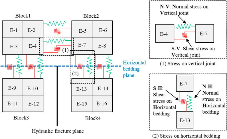
FIGURE 2. Schematic diagram of stress location (Zheng et al., 2022).
In shear-failure bedding, hydraulic fracture failure mainly includes two forms. One is the tensile failure caused by the tensile stress at the front edge of the hydraulic fracture in the propagation direction. And the other is the shear failure of the bedding under the combined action of normal stress and shear stress on the bedding plane.
The effect of in-situ stress can be analyzed in terms of both the magnitude of the stress and the stress difference. The magnitude of the stress characterizes the initial value of the in-situ stress and its magnitude is mainly influenced by the burial depth of the reservoir. The difference of in-situ stress characterizes the stress difference reflected by tectonic stress in the reservoir. Consequently, the effects of the initial in-situ stress value and the in-situ stress difference on the hydraulic fracture propagation are analyzed separately.
To investigate the effect of stress magnitude on the hydraulic fracture propagation under uniform stress conditions, we assume that the stress is equal in three directions. Five cases with stress of 5 MPa, 10 MPa, 15 MPa, 20 MPa and 25 MPa are established. The injection rate is 5 mL/s. The fluid viscosity is 10 cp and the injection time is 20 s. Then the above five cases are calculated separately.
The propagation results are shown in Figure 3. In the all 5 cases, the hydraulic fractures fail to cross bedding plane. However, the fracture morphology varies under different stress conditions. When the stress is low (5 MPa), the hydraulic fracture fails to pass through the bedding plane after encountering it. Due to the barrier effect of bedding plane, hydraulic fractures propagate laterally. The hydraulic fractures turn and propagate along the bedding plane, but the extension range is not far. With the increase of in-situ stress, the extension range of hydraulic fractures decreases. In addition, when the stress is 5 MPa, the length of hydraulic fracture is the largest. With the increase of stress, the fracture length becomes shorter. The reduction of extension area on bedding plane and fracture length means that the fracturing volume is reduced. When the stress is 25 MPa, the hydraulic fracture has not yet propagated to the bedding plane under the same liquid injection volume. In conclusion, the initial stress magnitude controls the extension range of hydraulic fractures. Under high stress conditions, the propagation difficulty of hydraulic fractures increases, so the propagation speed of hydraulic fractures slows down and the extension range decreases.
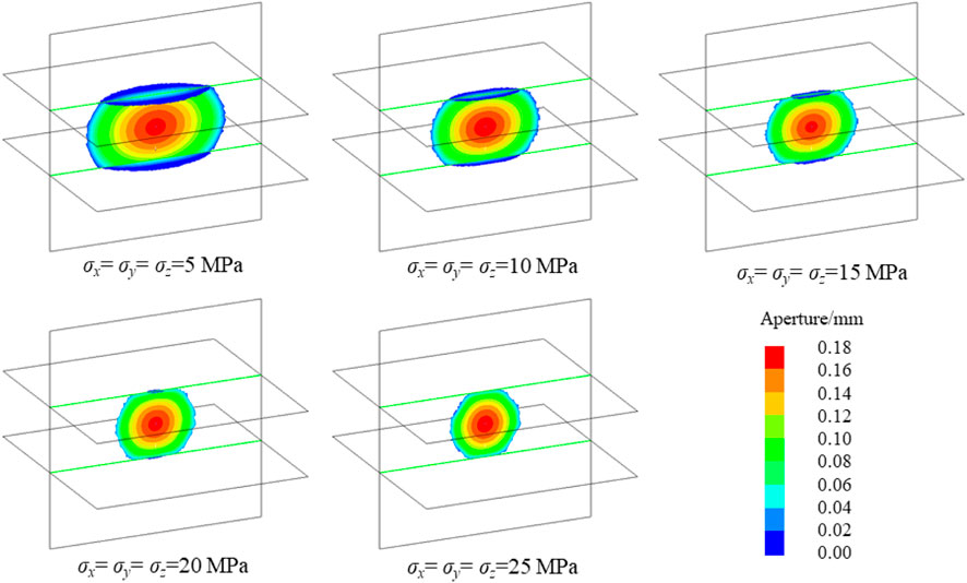
FIGURE 3. Fracture propagation morphology under uniform in-situ stress.
The magnitude of in-situ stress reflects the burial depth of the reservoir. And the deeper the reservoir, the greater the in-situ stress. Therefore, with the increase of burial depth, the difficulty of propagation increases. To obtain the same extension range, more liquid injection is required. When the stress is different, the fracture extension range is different for the same liquid injection volume. Since the stress induced by the fluid in the formation is caused by fluid compression, the formation pressure will be higher under the condition of high in-situ stress. Therefore, the evolution of injection pressure under different stress states is analyzed in Figure 4. The liquid injection pressure increases with the increase of stress. Therefore, fracturing in deep reservoirs requires higher pressure and higher power equipment.
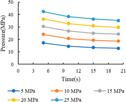
FIGURE 4. Fluid injection pressure under uniform in-situ stress.
In conclusion, high stress reservoirs require higher injection pressure. In this simulation, the initiation strength of the five cases is the same, so the fracture initiation is controlled by the stress state. The stress state on the joint is the result of the combined effect of the initial stress field of the formation and the included stress by liquid injection. The formation is compressed and the opening of the fracture is the result of the tension of the fracture surface. Therefore, the opening of the fracture requires the induced stress by liquid injection to overcome the initial stress. Taking N-V stress as an example, the initial N-V is the compressive stress, and the opening of hydraulic fractures requires N-V to change into a tensile state and be greater than the tensile strength of the joint (10 MPa in this cases). Therefore, the larger the initial stress, the larger the range of N-V from compression to tension. This explains why it is more difficult to propagate for hydraulic fractures under high in-situ stress conditions.
Hydraulic fracture propagation is the result of stress action. Its propagation behavior at the bedding plane is determined by the stress state at the intersection of hydraulic fracture and bedding plane. As mentioned above, the failure in the failure of shear-failure bedding is mainly the tensile failure of vertical joints and the shear failure of horizontal beddings. The tensile failure of vertical joints is determined by N-V. According to Coulomb slip criterion of bedding plane, shear failure of horizontal bedding is determined by normal stress (N-H) and shear stress (S-H) on bedding plane. Therefore, the stress curve at the intersection is extracted and summarized in Figure 5.
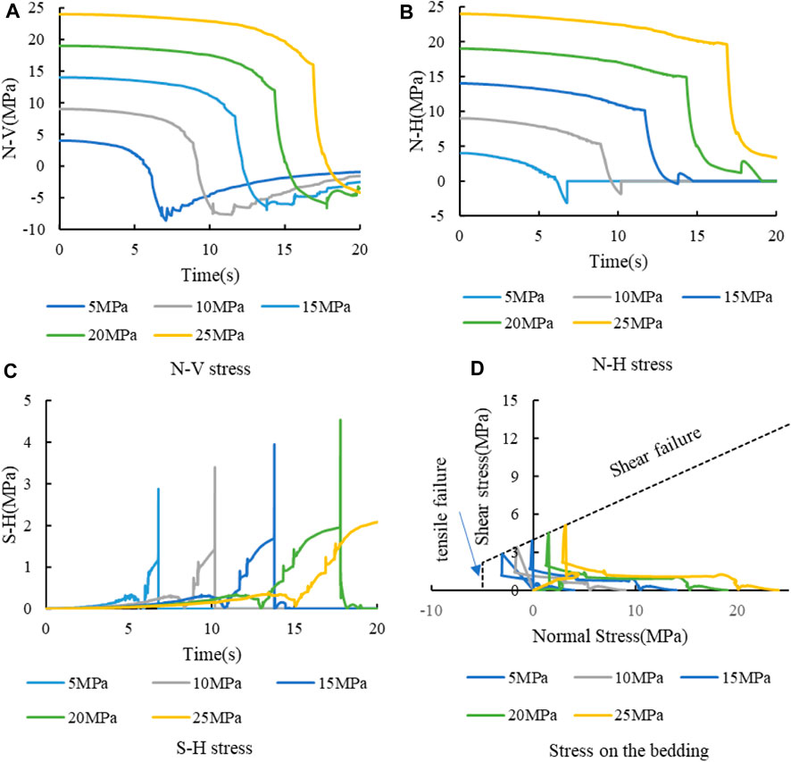
FIGURE 5. Stress curve at the intersection of hydraulic fracture and bedding plane. (A) N-V stress. (B) N-H stress. (C) S-H stress. (D) Stress on the bedding.
Figure 5A shows the N-V stress curve at the intersection. According to the figure, the N-V curve can be divided into three stages. The first stage is the slight decrease stage, in which the fracture tip is far from the intersection point. The induced stress caused by hydraulic fractures is small and has little influence on the total stress at the intersection point. The second stage is the rapid decrease stage, in which the fracture tip approaches and finally reaches the intersection point. At this time, the induced stress by hydraulic fracture has a great influence on this point, so the stress curve drops rapidly. According to the minimum value of each curve in Figure 5, the N-V fails to meet the tensile strength of the vertical joint. Consequently, the hydraulic fracture cannot propagate vertically and cross the bedding plane. In addition, the analysis of the starting time of this stage (when the curve starts to drop rapidly) shows that the greater the stress, the later the starting time. The late starting time means that it takes more time for the fracture to meet the bedding plane, which is caused by the slow propagation speed of hydraulic fracture under high stress conditions. The third stage is the gradual recovery stage. In this stage, N-V does not reach the tensile strength of the vertical joint, and the hydraulic fracture turns to the bedding plane. It results that the interference stress of the hydraulic fracture mainly acts on the bedding plane. Therefore, the tensile stress on the stress curve gradually decreases, and it shows a slow recovery on the curve. Finally, the curve finally approaches zero.
Figure 5B shows the N-H stress curve. Similar to the N-V curve, the N-H curve shows a slight decrease at the early stage. When the hydraulic fractures approach the intersection, the stress drops rapidly. When the bedding plane is sheared, the connection at this point is broken. Now, N-H becomes 0. Compared with the initial stage, the N-H has a greater drop than the initial stress. According to the Coulomb slip criterion, if the normal stress on the bedding plane decreases, the shear strength of the plane decreases. In conclusion, the N-H curve is higher under high stress conditions.
Figure 5C shows the S-H stress evolution curve. When the hydraulic fracture is far from the intersection, the value of shear stress is low. With the approaching of hydraulic fracture, the shear stress increases gradually. When the hydraulic fracture reaches the bedding plane, the shear stress increases rapidly. Finally, shear failure occurs at the intersection, and the shear stress decreases. It can be seen from the figure that the maximum shear stress increases with the increase of initial stress.
Figure 5D shows the N-H and S-H stress evolution. The dotted line in the figure is the critical curve for the failure of the bedding plane. The vertical dotted line on the left side of the curve indicates the tensile failure of the bedding plane, while the diagonal dotted line on the right side indicates the shear failure of the bedding plane. It can be seen from the figure that shear failure occurred to the bedding plane in all five cases. It can also be seen from the evolution law of the curve that the normal stress on the bedding plane decreases and the shear stress increases with time. Under low stress conditions (5 MPa and 10 MPa), N-H is in tension when it is damaged. Under high stress conditions (20 MPa and 25 MPa), N-H is under compression when the bedding plane is damaged. From the analysis of stress variation difference, the normal stress reduction value and the shear stress increase value on the bedding plane are higher under high stress conditions. The change of stress requires the supply of injected fracturing fluid, so the difficulty of hydraulic fracture expansion under high stress conditions increases.
The influence of different initial stresses on fracture propagation with uniform in-situ stress has been investigated. Based on the simulation scheme in the previous section, we set the difference between vertical stress and horizontal stress as 5 MPa, and the fluid injection time is increased to 30 s. But other parameters are consistent with those in the previous section. The details about simulation cases are shown in Figure 6.
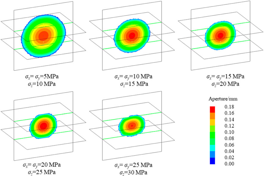
FIGURE 6. Fracture propagation with non-uniform stress (difference is 5 MPa).
Figure 6 shows the fracture propagation under non-uniform in-situ stress. In the five cases, due to the difference between the vertical stress and the horizontal stress, the hydraulic fracture can cross the bedding plane. The increase of vertical stress leads to the increase of normal stress on the bedding plane, which improves the shear strength of the bedding plane. From the perspective of initial stress, when the initial stress is low, the hydraulic fracture has a large expansion range and the fracture is uniform and circular. With the increase of initial stress magnitude, the difficulty of hydraulic fracture propagation increases, and the expansion range decreases gradually. In addition, when the initial horizontal stress is 25 MPa, the propagation of the hydraulic fracture is hindered when it meets the bedding plane. The hydraulic fractures first extend along the length of the fractures, and then gradually break through the bedding plane and expand vertically. In conclusion, the initial in-situ stress mainly affects the difficulty of hydraulic fracture propagation. The higher the initial stress is, the slower the propagation speed of hydraulic fracture is under the same construction parameters. Therefore, according to different in-situ stress conditions, appropriate construction parameters should be determined. On the basis of ensuring the shape of hydraulic fractures, parameters such as fluid injection rate should be appropriately increased to improve the efficiency of fracturing construction.
Figure 7 illustrates the injection pressure under different horizontal stress conditions. Similarly, the injection pressure decreases as the fracture propagates. It is easy to know that the injection pressure is positively correlated with the initial stress by analyzing different cases. The higher the initial stress is, the greater the stress difference required for N-V to decrease from the initial value to cracking. It results in the higher induced stress by pressure in fracture. Analysis of the stress differences among the cases demonstrates that the differences between adjacent curves are relatively uniform at the same time point.
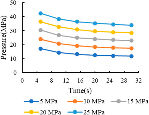
FIGURE 7. Injection pressure change with different horizontal stress σx (difference is 5 MPa).
Figure 8 presents the stress curves at the intersection. Figure 8A illustrates the N-V curve. All the hydraulic fractures cross the bedding plane and propagate along the vertical joints, so N-V is the key factor to determine the fracture propagation. From the figure, N-V are reduced from the initial stress to −10 MPa. By analyzing the curves, it can be obtained that the N-V curve is basically decreased directly to −10 MPa in the rapid decrease stage when the initial horizontal stresses is 5 MPa and 10 MPa. And as the initial stress rises, the falling rate of the N-V curve slows down in the later part of the rapid decrease stage. The duration of the slowing zone increases significantly with the increase of the initial stress. Combined with the change of fracture propagation pattern analyzed in Figure 6, the reason for the slowing down of the interval may be related to the obstruction of hydraulic fractures on the bedding plane. According to the stress curve, the N-V at the intersection has not yet reduced to −10 MPa when the hydraulic fracture approaches the bedding plane. So, the fracture cannot continue to propagate upward. However, due to the high vertical initial stress, the hydraulic fractures also cannot meet the condition of turning toward the bedding. So, the fracture expansion is hindered in vertical and horizontal direction and it can only propagate along the length direction. The N-V at the intersection reduces to −10 MPa when the fracture propagates for a certain length, and at this time the hydraulic fracture crosses the bedding plane. It is noteworthy that the duration of slowing zone increases due to the higher difficulty of fracture propagation under high stress conditions. That means the obstruction of bedding is slight after encountering the bedding plane and hydraulic fracture can cross the bedding plane rapidly when the initial stress is low. While under high stress conditions, the hydraulic fracture is hindered by the bedding plane, and it takes some time for the hydraulic fracture to pass through the bedding plane.
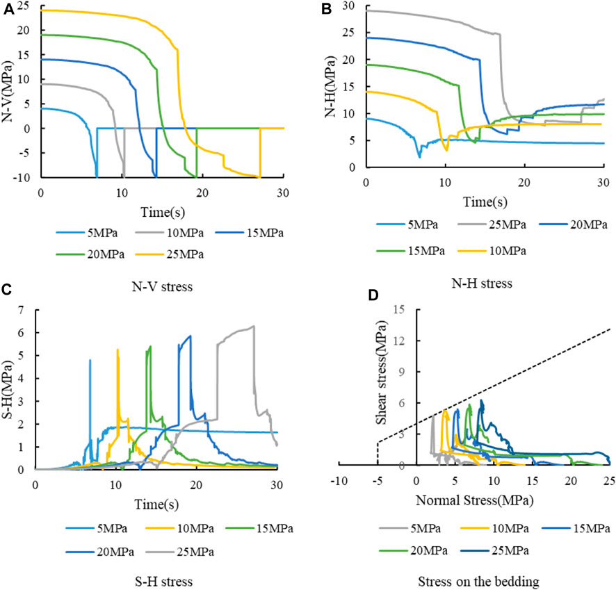
FIGURE 8. Stress curve at the intersection with different horizontal stress σx. (A) N-V stress. (B) N-H stress. (C) S-H stress. (D) Stress on the bedding.
Figure 8B shows the N-H stress evolution curve. Similar to Figure 5B, N-H stress decreases gradually. However, due to the high initial stress, the lowest value of the stress curve is still greater than 0, which means that the bedding plane is always in compression. When the initial stress is low, the reduction of N-H curve is low. However, due to the low initial value, its minimum value is the lowest. With the increase of initial stress, the reduction of N-H stress increases. However, due to the increase of the initial value, the minimum value of the final N-H stress increases with the increase of the initial stress.
Figure 8C presents the S-H curve. The shear stress has a jump rise when the hydraulic fracture reaches the intersection point. However, it still cannot meet the shear failure strength yet. Consequently, the shear stress remains at a higher value and increases slightly. Similar to the flat phase of N-V, there is also a slightly rising phase in S-H. When the hydraulic fracture crosses the bedding plane, the S-H curve drops suddenly. As can be seen from the figure, the duration of the flat phase becomes longer as the initial stress value rises. This is same as the N-V curve, both are influenced by the fracture barrier effect. That is, the barrier effect of bedding plane on hydraulic fracture is enhanced under high stress conditions.
Figure 8D shows the evolution curves of the normal and shear stresses on the bedding plane. At the low stress condition, the bedding plane reached the condition of shear failure, but the hydraulic fracture did not propagate along the bedding plane due to the presence of stress difference. At high initial stress, the stress on the bedding plane does not reach the shear failure condition. Due to the high initial vertical stress, the bedding plane is always under compression.
The effect of the initial stress magnitude was explored in the previous section, and the result shows that the magnitude of the initial stress value affects the propagation difficulty of the hydraulic fracture. The greater the initial stress, the more difficult it is for the hydraulic fracture to propagate. In addition to the initial stress magnitude, stress difference has an important effect on the propagation morphology of hydraulic fractures. Therefore, this section addresses the effect of stress difference. Stress difference refers to the difference between vertical stress and horizontal stress. Changes in both vertical stress and horizontal stress will cause changes in stress difference, so the influence of vertical stress and horizontal stress are analyzed separately here.
In order to investigate the effect of vertical stress on hydraulic fracture propagation, the horizontal stress was set to 15 MPa and the vertical stress was set to 16 MPa, 17 MPa, 18 MPa, 19 MPa, and 20 MPa, respectively, which means the stress difference was 1–5 MPa. The injection time was 30 s. The hydraulic fracture propagation patterns under different cases are presented in Figure 9. When the vertical stress is low, the stress difference is small and the hydraulic fracture fails to cross the bedding plane, but turns to the bedding plane. Meanwhile, the hydraulic fracture propagates along the length direction. When the vertical stress is high, the stress difference is large and the hydraulic fracture cross the bedding plane directly. In summary, the hydraulic fracture penetration behavior is influenced by the stress difference, and the tendency of hydraulic fracture penetration increases when the difference between vertical stress and horizontal stress grows.
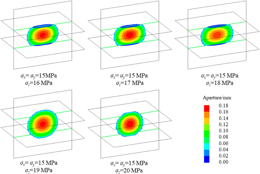
FIGURE 9. Fracture propagation of different vertical stresses (σx=15 MPa).
Figure 10 illustrates the injection pressure under different cases. The figure shows that the injection pressure curve is basically the same. It can be divided into two groups according to fracture morphology (cross and capture, in Figure 9). The pressure curves of the two groups were basically the same before 15 s. Then the injection pressure of capture is slightly higher than that of the cross during 15 s–30 s. In the same group, the injection pressure increased slightly with the growth of vertical stress, but the difference was not obvious. Hence, if hydraulic fracture mainly propagates in the vertical joints, the injection pressure is mainly controlled by the horizontal stress and is little influenced by the vertical stress. The vertical stress mainly affects the normal stress on the bedding plane. It limits the fracture turning to bedding plane by increase the normal stress on the bedding plane.
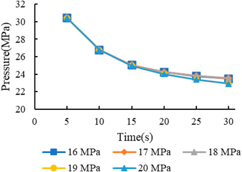
FIGURE 10. Injection pressure with different vertical stresses σz (σx=15 MPa).
Figure 11 shows the stress curve at the intersection. Figure 11A shows the N-V stress evolution curve. The stress curve overlaps before 15 s, indicating that the fracture propagation is controlled by horizontal stress before the hydraulic fracture encounters the bedding plane. During 15–30 s, the fractures can be divided into 2 groups according to their morphologies (cross and capture). The fracture turns to the bedding plane under the condition of low vertical stress, so the N-V can continue to maintain a certain stress and gradually tends to 0. Under the high vertical stress condition (19 MPa and 20 MPa), the hydraulic fracture crosses the bedding plane, that is why N-V becomes 0 directly and the two curves coincide. This is due to the fact that the propagation is not affected by vertical stress when a hydraulic fracture crosses the layer.
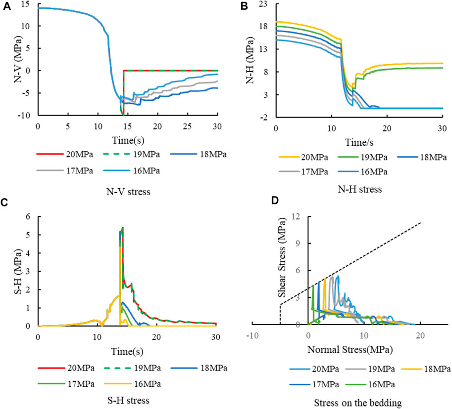
FIGURE 11. Stress curve at intersection with different vertical stresses σz (σx=15 MPa). (A) N-V stress. (B) N-H stress. (C) S-H stress. (D) Stress on the bedding.
Figure 11B shows the N-H stress evolution curve. In the first half of the curve (0–15 s), the difference between the curves remains the same. It results that the minimum value of N-H under low vertical stress is small. Low N-H stress means that the shear strength of the bedding is not high and the bedding is more prone to shear failure resulting in the propagation of hydraulic fractures along the bedding plane. In conclusion, the effect of vertical stress on hydraulic fracture penetration is mainly through influencing the normal stress on the bedding plane, which then influences the shear strength of the bedding plane and finally determines the penetration behavior of the hydraulic fracture. During 15–30 s, the curves can be divided into two groups according to the failure state. However, the stress has no significant effect on the fracture propagation in this stage.
Figure 11C shows the S-H stress evolution curve. The shear stress curves coincide before the hydraulic fractures reach the bedding plane. After the hydraulic fracture meets the bedding plane, the shear stress shows slight difference. Figure 11D shows the stress path on the bedding plane. It can be seen from the figure that in the cases where fractures are captured (vertical stress is 16–18 MPa), the shear stress increases slightly with the increase of vertical stress. However, the main reason for its shear failure is that the low N-H leads to the reduction of the shear strength of the bedding plane. In this case, the shear failure of the bedding can occur under the condition of low shear stress.
In conclusion, the essence of the influence mechanism of vertical stress on the bedding behavior of hydraulic fractures is to change the normal stress on the bedding plane, and then affect the shear strength of the horizontal bedding plane. For bedding plane, the vertical stress is the normal stress on the surface. Under the condition of low stress difference, the vertical stress is small. So, the normal stress on the bedding plane is small. It results in the low shear strength of bedding. Therefore, the bedding plane is prone to shear failure in this case. After the shear failure of the bedding plane, the hydraulic fracture can expand along the bedding plane. In this way, the normal stress on the vertical joint cannot be transferred effectively. Therefore, the hydraulic fractures cannot continue to expand vertically.
In addition to the vertical stress, the horizontal stress is another key to the stress difference. In order to analyze the influence of horizontal stress, the vertical stress is set as 15 MPa, and the horizontal stress is set as 14 MPa, 13 MPa, 12 MPa, 11 MPa and 10 MPa respectively, that is, the stress difference is 1–5 MPa. And other parameters are the same as 3.2.1.
Figure 12 presents the fracture propagation under five cases. From the perspective of stress difference, the results are similar to those in Section 3.2.1. Under the condition of low stress difference, the hydraulic fractures fail to cross the bedding plane. And the hydraulic fractures propagate along the bedding plane and mainly along the fracture length. However, under the condition of high stress difference, the hydraulic fractures continue to propagate vertically through the bedding plane. From the perspective of horizontal stress, the reduction of horizontal stress increases the possibility of hydraulic fracture penetrating the bedding plane.
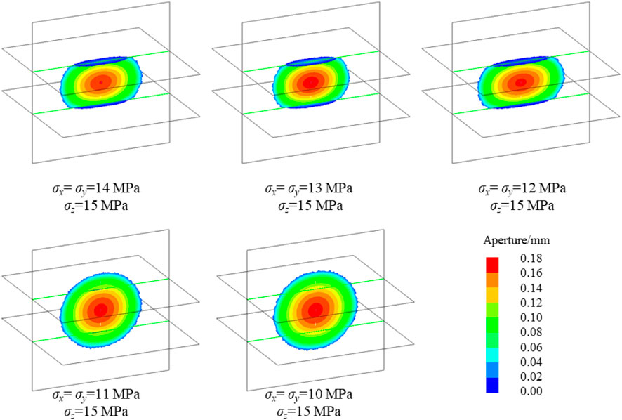
FIGURE 12. Fracture propagation under different horizontal stresses (σz=15 MPa).
Figure 13 shows the fluid injection pressure under different horizontal stress. As can be seen from the figure, the injection pressure drops with the decrease of horizontal stress. This is because the expansion of hydraulic fractures is mainly in the vertical joint plane, so the injection pressure is mainly related to the normal stress (for vertical joint, the normal stress is horizontal stress) of the fracture plane. Note the difference between adjacent curves at the same time point. At the beginning, the difference between the curves is basically the same. In the later stage (such as 30 s), it is divided into two groups according to the fracture morphology. The maximum spacing is between 11 MPa and 12 MPa. The fracture shape corresponding to 11 MPa is crossing, and the fracture shape corresponding to 12 MPa is captured. According to the pressure difference, the pressure of the hydraulic fracture after penetrating the bedding is low. This shows that the expansion difficulty of hydraulic fracture after penetrating the bedding is lower than that of capture in this case.
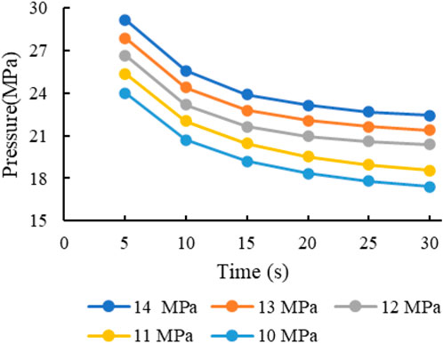
FIGURE 13. Injection pressure with different horizontal stresses σx (σz=15 MPa).
Figure 14 shows the stress evolution curve at intersection. And Figure 14A shows the N-V stress evolution curve. The curves in the figure can be divided into two categories according to the fracture morphology. The hydraulic fracture crosses the bedding plane when the horizontal stress is low (10 MPa and 11 MPa). When the N-V curve is reduced to −10 MPa, the tensile strength of the vertical joint is reached. After fracture cracking, the joint connection fails and the normal stress becomes 0. The stress is not reduced to −10 MPa when the horizontal stress is high because of the high initial value of N-V. At this time, the bedding plane meets the shear failure, so the hydraulic fracture turns toward the bedding plane. Consequently, the mechanism of horizontal stress on hydraulic fracture penetration is mainly the evolution of N-V stress. When the horizontal stress is low, the reduction value of N-V from the initial value to the failure criterion is small. On the contrary, when the horizontal stress is high, the initial stress of N-V is high, which rises the range of stress reduction and makes it difficult for the hydraulic fracture to continue vertical propagation.
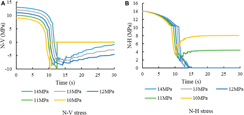
FIGURE 14. Stress curve at intersection with different horizontal stresses σx (σz=15 MPa). (A) N-V stress. (B) N-H stress.
Figure 14B shows the N-H curve. It can be seen from the figure that the lowest value of the curve before failure decreases with the increase of horizontal stress. This shows that the higher the horizontal stress is, the greater the reduction of N-H. According to Figure 13, the higher the horizontal stress, the greater the injection pressure. Stress disturbance was caused by fracturing fluid injection. The N-H reduction is the result of induced stress by injection. Therefore, the high horizontal stress leads to a large decrease of N-H. Under low horizontal stress, N-H only decreases slightly. This leads to high N-H. According to Coulomb slip theory, high N-H means high shear strength of bedding plane. Here, the difficulty of shear failure of bedding plane increases. It results in an increase in the probability of hydraulic fracture crossing the bedding plane.
The influence of horizontal stress on N-V and N-H are comprehensively considered. On the one hand, low horizontal stress results in low initial value of N-V. The low N-V reduces the tensile strength of vertical joints. This is conducive to the vertical propagation of hydraulic fractures. On the other hand, low horizontal stress leads to a higher value of N-H, which increases the shear strength of the bedding plane and is not conducive to the hydraulic fracture turning to the bedding plane. In conclusion, low horizontal stress is conducive to hydraulic fracture penetration.
The fracture propagation law of shear-failure bedding plane is analyzed above. Combined with stress analysis, it can be seen that the normal stress on the bedding plane decreases gradually in the process of hydraulic fracture propagation. With the decrease of stress, the bedding plane changes from compression to tension. If the tensile strength of bedding plane is low, tensile failure may occur on the bedding plane. Therefore, the analysis of tensile failure bedding is carried out to explore the influence mechanism of stress on the fracture propagation law in tensile-failure bedding plane. There are two main propagation modes of hydraulics fractures in the tensile-failure bedding model. One is the tensile failure of the vertical bedding plane. The hydraulic fracture propagating vertically and crosses the bedding plane in this model. Another is the tensile failure of the bedding plane. The hydraulic fractures will turn and propagating along the bedding plane in this model.
Studies have shown that the initial stress magnitude has a significant impact on fracture morphology. In order to analyze the influence of initial stress on fracture morphology, the difference between horizontal stress and vertical stress is set to 2 MPa. The initial horizontal stress is 20 MPa, 15 MPa, 10 MPa and 5 MPa respectively. The injection rate is 5 mL/s. The viscosity of fracturing fluid is 1 cp. And the injection time is 25 s. The results of the above 4 cases are shown in Figure 15.
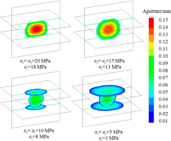
FIGURE 15. Fracture morphology of different initial stress.
The results show that the initial stress affects the fracture propagation. When the initial horizontal stress is 20 MPa, the hydraulic fracture cannot cross the bedding plane, and the fractures mainly propagating along the length direction and the fracture height is limited. When the initial horizontal stress is 15 MPa, the hydraulic fracture crosses the bedding plane and continues to propagate vertically. As the initial horizontal stress decreases, the fracture morphology changes, and the hydraulic fracture cannot cross the bedding plane. The hydraulic fracture turns and spreads along the bedding plane. When the initial horizontal stress is 5 MPa, the range of fracture is obviously larger than that of 10 MPa. From the perspective of fracture range, it is affected by the initial stress. The higher the initial stress is, the smaller the fracture range is. This is consistent with the conclusion in the shear-failure bedding plane. In addition to the influence on the propagation range, the initial stress value also affects the fracture morphology. A small initial stress value will increase the tendency of hydraulic fractures to be captured. From the analysis of fracture aperture, it can be seen that the increase of initial stress will increase the aperture. As discussed in last section, the initial stress affects the fluid pressure in the fracture. The greater the pressure in the fracture, the greater the fracture deformation. For this kind of bedding, the stress difference is not the only factor that affects the fracture penetration behavior. When fracturing is carried out in reservoirs with different burial depths, the stress of the formation shall be evaluated in detail. Then fracturing design is carried out according to different initial stresses.
Stress is the essence of fracture propagation. And in the simulation of tensile-failure bedding, it is mainly the vertical propagation of hydraulic fracture (tensile failure) and the tensile failure of horizontal bedding. Therefore, only the normal stress at the intersection should be analyzed. The stress evolution curves of the four cases are extracted respectively, and the results are shown in Figure 16.
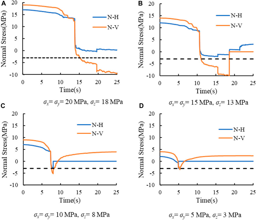
FIGURE 16. Stress curves of different initial stress values. (A) σx = σy = 20 MPa, σz = 18 MPa. (B) σx = σy = 15 MPa, σz = 13 MPa. (C) σx = σy 10 MPa, σz = 8 MPa. (D) σx = σy = 5 MPa, σz = 3 MPa.
It can be seen from the figure that in the early stage of hydraulic fracture propagation, the normal stress N-H and N-V are in a slow decline stage. When the hydraulic fracture approaches the bedding plane, the normal stress enters a rapid decline stage. Figure 16A shows the stress evolution curve with an initial horizontal stress of 20 MPa. After the hydraulic fracture encounters the bedding plane (after the rapid decline stage, about 14 s later), the N-H stress on the bedding plane does not reach −3 MPa (tensile strength for tensile-failure bedding), and N-V does not drop to −10 MPa (tensile strength for vertical joint). Therefore, both tensile failures will not occur. Due to the high shear strength of the bedding plane, shear failure will not occur, so the fracture is limited to the bedding plane and can only propagate in the length direction. At this stage, both N-H and N-V decrease slowly, and when one stress meets the failure criterion, the hydraulic fracture continues to propagate outward. According to the curve in the figure, N-V can reach −10 MPa. Therefore, it can be predicted that under this case, the hydraulic fracture will eventually cross the bedding plane and continue to propagate vertically.
Figure 16B shows the stress curve under the condition that the horizontal stress is 15 MPa. In those cases, the stress does not meet any failure criterion after the hydraulic fracture meets the bedding plane. So, N-H and N-V enter the slightly decline stage. Finally, the N-V reaches −10 MPa, and the hydraulic fracture crosses the bedding plane.
Figure 16C is the stress evolution curve with an initial horizontal stress of 10 MPa. Due to the low initial stress, the N-H has been reduced to-3 MPa in the rapid decline stage. So, the tensile failure of the bedding plane occurs. Then the fracturing fluid enters the bedding plane, and the hydraulic fracture continues to propagate along the bedding plane.
Similarly, Figure 16D shows the stress curve under the condition that the initial horizontal stress is 5 MPa. N-H first decreases to −3 MPa, tensile failure occurs on the bedding surface, and hydraulic fractures propagate along the bedding plane. Comparing Figures 16C, 16d, the latter has a shorter initial time. There are two reasons for it. First, fractures are easy to expand under low stress conditions. Second, the initial value of N-H is small, and the required reduction range to reduce to—3 MPa is small.
The cross or captured of hydraulic fractures is related to the decrease of N-H and N-V. The higher the initial stress, the greater the required reduction range to reach the critical stress. Figure 17 analyzes the initial values, minimum values and stress drops of N-H and N-V under different cases. According to the figure, and the decreases of N-H and N-V increased with the increase of initial stress. Therefore, the increase of initial stress will increase the difficulty of fracture failure. By comparing N-H and N-V, it can be seen that the reduction of N-V is greater than that of N-H. Combined with the stress curve, when the initial horizontal stress is 20 MPa and 15 MPa, the reduction rate of N-H is smaller than that of N-V. Therefore, N-V first reaches the failure condition, and the hydraulic fracture will directly cross the bedding plane. When the initial horizontal stress is 10 MPa and 5 MPa, both N-H and N-V are in the rapid reduction stage, and the initial value of stress is low. N-H can reach—3 MPa in the rapid reduction stage, so the bedding is first subject to tensile failure. In conclusion, the internal reason for the influence of initial stress on the behavior of hydraulic fracture penetration is that the lower initial stress can ensure that the N-H stress has reached the tensile strength of the bedding plane in the rapid reduction stage.
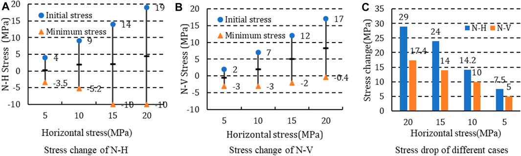
FIGURE 17. Stress drop under different cases (stress difference is 2 MPa). (A) Stress change of N-H. (B) Stress change of N-V. (C) Stress drop of different cases.
The stress difference has a significant effect on the penetration behavior of hydraulic fractures. In order to analyze the influence of vertical stress on the behavior of hydraulic fractures, the horizontal stress is set to 10 MPa, and the vertical stresses are 6 MPa, 8 MPa, 10 MPa and 12 MPa, respectively. The corresponding stress differences (the vertical stress minus the horizontal stress) are −4 MPa, −2 MPa, 0 MPa and 2 MPa. The injection time is set to 15 s, and other parameters are consistent with above. Fracture propagation morphology under four cases is shown in Figure 18.
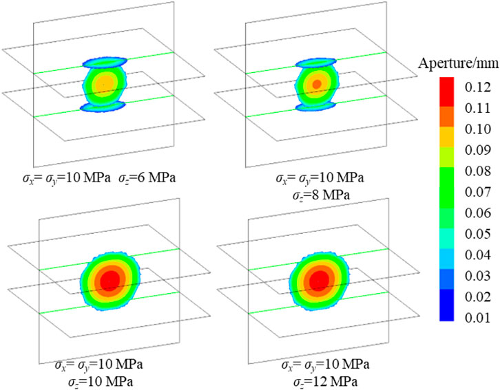
FIGURE 18. Fracture morphology with different vertical stresses.
The forms of hydraulic fractures are different with different vertical stress. When the vertical stress is small (6 MPa and 8 MPa), the hydraulic fractures propagate along the bedding plane. When the vertical stress is large (10 MPa and 12 MPa), the hydraulic fractures propagate vertically through the bedding plane. This shows that with the increase of vertical stress, the difficulty of hydraulic fracture turning to bedding plane increases. And the vertical stress affects the aperture of the fracture. The smaller the vertical stress, the smaller the maximum aperture of the fracture.
Comparing the morphology of captured fracture in shear-failure bedding (e.g., Figure 3; Figure 9; Figure 12) and tensile-failure bedding (e.g., Figure 15; Figure 18), the former will still propagate in the direction of fracture length after shear failure on the bedding plane, while the propagation distance on the bedding plane is shorter. The fracture morphology of the latter tends to extend along the bedding plane, and the fracture length is shorter than shear-failure type. This is related to the failure form of both. The failure mode of shear-failure type bedding is shear failure. However, the fractures may not open after the shear failure of bedding. When the pressure inside the fractures overcomes the normal stress of the fracture surface, the fracture opens. The shear stress caused by hydraulic fractures mainly acts near the intersection line. The shear stress far away from the intersection line decreases, which cannot cause the shear failure of the bedding plane. In addition, the tensile strength of the bedding is high, and the bedding is difficult to meet the requirements of tensile failure. Therefore, the fractures are limited between bedding planes and can only extend along the length direction. In tension-failure bedding, the failure mode of bedding is tension failure. And the fracturing fluid directly enters the bedding plane after failure. The tensile strength of the bedding plane is low, so the fluid pressure in the bedding plane can ensure the fracture expansion. Even because the strength of bedding plane is far lower than that of rock mass, bedding plane has become the main channel for hydraulic fracture expansion.
According to the stress evolution curves (summarized in Figure 19), N-H is divided into two categories according to the fracture morphology. When the vertical stress is low, the N-H curve can be divided into slightly reduction stage, rapid reduction stage and flat stage. Firstly, before the hydraulic fracture reaches the bedding plane, the induced stress of N-H is small, and the curve shows a slow decline. When the hydraulic fracture approaches the bedding plane, the N-H decreases rapidly due to the induced stress caused by the fracture. When it is reduced to −3 MPa, the fracture opens due to tensile failure of bedding plane. Then the N-H becomes 0. When the bedding plane is opened, the fracturing fluid enters the bedding plane. Because of the low tensile strength of the bedding plane, the hydraulic fractures propagate along the horizontal bedding plane. When the vertical stress is large, N-H is always greater than −3 MPa, so no tensile failure occurs on the bedding plane.
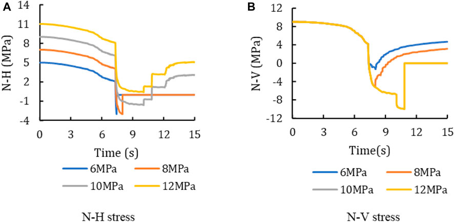
FIGURE 19. Stress evolution curve at intersection with different vertical stress σz (σx=σy=10 MPa). (A) N-H stress. (B) N-V stress.
The analysis of the N-V curve shows that before the hydraulic fracture meets the bedding plane (about 7 s), the stress curves coincide. After encountering the bedding plane, N-H is reduced to −3 MPa during rapid reduction stage due to the small initial N-H of the low vertical stress, resulting in bedding failure and fracture deflection. Therefore, N-V cannot be further reduced. However, when the vertical stress is high, the initial N-H is high, and the N-H is still greater than-3 MPa after the rapid reduction stage. The bedding plane is not destroyed, and the N-H enters the slow reduction stage. Therefore, N-V can continue to decline. When N-V drops to −10 MPa, the hydraulic fractures propagate vertically.
In conclusion, the effect of vertical stress on the penetration behavior of hydraulic fractures is mainly to affect the initial value of N-H. When the vertical stress is low, the initial value of N-H is small. Therefore, it is easy for the bedding plane to change from compression to tension. On the contrary, when the vertical stress is high, the initial value of N-H is large, and the compressive stress on the bedding is large. So, it is difficult to change from compression to tension. If the bedding plane is not subject to tensile failure, the hydraulic fracture will expand vertically. In a word, with the increase of vertical stress, hydraulic fractures are easier to cross the bedding.
Horizontal stress is another key factor causing stress difference. In order to analyze the influence of horizontal stress on fracture propagation, the vertical stress is set to 10 MPa. And the horizontal stresses are 8 MPa, 10 MPa, 12 MPa and 14 MPa, respectively. The difference between vertical stress and horizontal stress is 2 MPa, 0 MPa, −2 MPa and −4 MPa, respectively. The injection time is 15 s, and the other parameters are the same as the previous section. The results are shown in Figure 20.
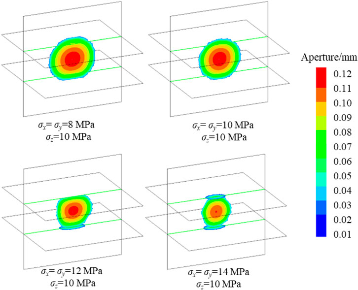
FIGURE 20. Fracture morphology under different vertical stresses.
According to the figure, when the horizontal stress is small (8 MPa and 10 MPa), the hydraulic fractures cross the bedding plane. As the horizontal stress increases (12 MPa and 14 MPa), the hydraulic fractures are captured by the bedding plane. Combined with the stress evolution curve (Figure 21), when the horizontal stress is small, the initial value of N-V is low. Therefore, the pressure in the fracture required for the vertical propagation of the fracture is small. The decrease of N-V required for vertical fracture propagation is small, which leads to the small induced stress by hydraulic fractures. However, the initial value of N-H is the same, and the N-H cannot be reduced to −3 MPa under low stress conditions. So, the bedding plane will not be damaged. Owing to the low initial value of N-V, the hydraulic fracture first reaches −10 MPa, resulting in vertical propagation of hydraulic fracture. On the contrary, if the horizontal stress is high, the fracture pressure during the vertical propagation is large. High pressure leads large induced stress, resulting in the N-H decreasing to −3 MPa at first. Then, the hydraulic fractures will propagate along the bedding plane.
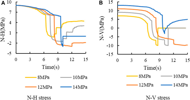
FIGURE 21. Stress curve at intersection with different horizontal stress σx (σz =10 MPa). (A) N-H stress. (B) N-V stress.
To sum up, the influence of vertical stress on fracture morphology is mainly on the initial value of N-H. The higher vertical stress leads to the increase of the initial normal stress on the bedding plane, which increases the opening difficulty of the bedding plane. The influence of horizontal stress is divided into two aspects. On the one hand, horizontal stress affects the initial value of N-V, lower horizontal stress results in lower initial N-V value and less stress reduction required for N-V. On the other hand, if the horizontal stress is small, the vertical propagation difficulty of hydraulic fracture is low. So, the fracture pressure is small. Then the induced stress by pressure is small. As a result, the reduction of N-H is small and cannot meet the tensile criterion of bedding plane. It can be concluded that the increase of vertical stress or the decrease of horizontal stress will increase the tendency of hydraulic fractures crossing the bedding.
(1) According to the failure characteristics of the bedding plane, it can be divided into shear-failure bedding and tensile-failure bedding. The shear-failure bedding mainly considers the shear failure behavior on the bedding plane. While the tensile-failure bedding mainly focuses on the tensile behavior on the bedding plane. The failure characteristics of the two are also different. After the shear failure of the bedding plane, it is difficult for the bedding plane to maintain the shear failure, so the hydraulic fracture will propagate in the length direction. However, the tensile strength of tensile failure bedding plane is small in tensile-failure bedding. So, the bedding plane is the dominant path of fracture propagation, and the length of hydraulic fractures is shorter than the shear-failure bedding.
(2) The initial stress mainly affects the difficulty of hydraulic fracture propagation. The inherent mechanism is that the normal stress on the fracture needs to be reduced from the initial stress to the failure stress during the fracking. Therefore, the greater the initial stress, the greater the stress reduction required for fracture propagation. Therefore, the effect of initial stress on the fracture penetrating is summarized as follows: the smaller the initial stress is, the smaller the barrier effect of bedding plane on the hydraulic fracture penetration.
(3) The vertical stress mainly affects the normal stress on the bedding plane. For the shear-failure bedding plane, the vertical stress determines the shear strength of the bedding plane by affecting the normal stress on the bedding plane. The smaller the vertical stress, the lower the shear strength of the bedding plane. For tensile-failure bedding planes, vertical stress affects the difficulty of tensile failure of bedding planes. When vertical stress is small, the difficulty of tensile failure of bedding planes decreases. In consequence, the low vertical stress is conducive to the propagation of hydraulic fractures along the bedding plane, and the fractures are easier to be captured.
(4) The horizontal stress affects normal stress on vertical bedding planes. The large horizontal stress increases the difficulty of vertical propagation of hydraulic fractures. So, the increase of horizontal stress will aggravate the difficulty of hydraulic fracture crossing the bedding. In addition, due to the increase of the pressure in the fracture, the induced stress increases. Then, the stress reduction on the bedding plane increases, which reduces the difficulty of the failure of the bedding plane and is conducive to the hydraulic fracture turning to the bedding plane.
The original contributions presented in the study are included in the article/Supplementary Material, further inquiries can be directed to the corresponding author.
YB: Investigation, writing—original draft. YH: Writing—review and editing. XL: Visualization, writing—review and editing. JT: Writing—reviewing and editing. YZ: Writing—original draft, conceptualization, WW: supervision.
This work is supported by the Natural Science Starting Project of SWPU (No. 2022QHZ009).
YB was employed by Shanxi Wangjialing Coal Industry Co., Ltd.
The remaining authors declare that the research was conducted in the absence of any commercial or financial relationships that could be construed as a potential conflict of interest.
All claims expressed in this article are solely those of the authors and do not necessarily represent those of their affiliated organizations, or those of the publisher, the editors and the reviewers. Any product that may be evaluated in this article, or claim that may be made by its manufacturer, is not guaranteed or endorsed by the publisher.
Gao, Q., and Ahmad, G. (2020). Three dimensional finite element simulations of hydraulic fracture height growth in layered formations using a coupled hydro-mechanical model. Int. J. Rock Mech. Min. Sci. 125, 104137. doi:10.1016/j.ijrmms.2019.104137
Heng, S., Li, X., Zhang, X., and Li, Z. (2021). Mechanisms for the control of the complex propagation behaviour of hydraulic fractures in shale. J. Petroleum Sci. Eng. 200, 108417. doi:10.1016/j.petrol.2021.108417
Huang, J., Ma, X., Shahri, M., Safari, R., Yue, K., Mutlu, U., et al. (2016). in Hydraulic fracture growth and containment design in unconventional reservoirs[C]//50th Us Rock mechanics/geomechanics symposium, American Rock Mechanics Association.
Huang, L., Dontsov, E., Fu, H., Lei, Y., Weng, D., and Zhang, F. (2022). Hydraulic fracture height growth in layered rocks: Perspective from DEM simulation of different propagation regimes. Int. J. Solids Struct. 238, 111395. doi:10.1016/j.ijsolstr.2021.111395
Huang, L., He, R., Yang, Z., Tan, P., Chen, W., Li, X., et al. (2023). Exploring hydraulic fracture behavior in glutenite formation with strong heterogeneity and variable lithology based on DEM simulation. Eng. Fract. Mech. 278, 109020. doi:10.1016/j.engfracmech.2022.109020
Huang, L., Liu, J., Ji, Y., Gong, X., and Qin, L. (2018). A review of multiscale expansion of low permeability reservoir cracks. Petroleum 4, 115–125. doi:10.1016/j.petlm.2017.09.002
Huang, L., Liu, J., Zhang, F., Dontsov, E., and Damjanac, B. (2019). Exploring the influence of rock inherent heterogeneity and grain size on hydraulic fracturing using discrete element modeling. Int. J. Solids Struct. 176, 207–220. doi:10.1016/j.ijsolstr.2019.06.018
Huang, L., Liu, J., Zhang, F., Fu, H., Zhu, H., and Damjanac, B. (2020). 3D lattice modeling of hydraulic fracture initiation and near-wellbore propagation for different perforation models. J. Petroleum Sci. Eng. 191, 107169. doi:10.1016/j.petrol.2020.107169
Ji, Y., Wang, J., and Huang, L. (2015). Analysis on inflowing of the injecting Water in faulted formation[J]. Adv. Mech. Eng. 7 (6), 405–407. doi:10.1177/1687814015590294
Luo, H., Xie, J., Huang, L., Wu, J., Shi, X., Bai, X., et al. (2022). Multiscale sensitivity analysis of hydraulic fracturing parameters based on dimensionless analysis method[J]. Lithosphere 2022, 9708300. doi:10.2113/2022/9708300
Shicheng, Z., Sihai, L., and Yushi, Z. (2021). Experimental study on fracture height propagation during multi-stage fractu-ring of horizontal wells in shale oil reservoirs[J]. J. China Univ. Petroleum ( Ed. Nat. Sci. 45 (1), 77–86.
Tan, P., Jin, Y., and Pang, H. (2021). Hydraulic fracture vertical propagation behavior in transversely isotropic layered shale formation with transition zone using XFEM-based CZM method. Eng. Fract. Mech. 248, 107707. doi:10.1016/j.engfracmech.2021.107707
Tan, P., Pang, H., Zhang, R., Jin, Y., Zhou, Y., Kao, J., et al. (2020). Experimental investigation into hydraulic fracture geometry and proppant migration characteristics for southeastern Sichuan deep shale reservoirs. J. Petroleum Sci. Eng. 184, 106517. doi:10.1016/j.petrol.2019.106517
Tang, J., and Wu, K. (2018). A 3-D model for simulation of weak interface slippage for fracture height containment in shale reservoirs. Int. J. Solids Struct. 144, 248–264. doi:10.1016/j.ijsolstr.2018.05.007
Tong, Z., Wang, H., Li, F., Yuanzhao, L., Yushi, Z., and Chi, Z. (2020). Numerical simulation of hydraulic fracture propagation in laminated shale reservoirs[J]. Petroleum Explor. Dev. 47 (5), 1039–1051. doi:10.1016/s1876-3804(20)60122-7
Wang, S., Li, J., Dong, K., and Yang, Q. (2019). Research on the expansion mechanism of hydraulic fracture branching induced by weak bedding shear slip. Desalination Water Treat. 157, 219–227. doi:10.5004/dwt.2019.23849
Warpinski, N. R., Schmidt, R. A., and Northrop, D. A. (1982). In-situ stresses: The predominant influence on hydraulic fracture containment. J. Petroleum Technol. 34 (3), 653–664. doi:10.2118/8932-pa
Weng, X., Dimitry, C., Kresse, O., Prioul, R., and Wang, H. (2018). Hydraulic fracture-height containment by permeable weak bedding interfaces. Geophysics 83 (3), 137–152. doi:10.1190/geo2017-0048.1
Xiao, L., Hao, J., Yin, C., Huang, B., Li, G., Zhang, Z., et al. (2019). Characteristics of the shale bedding planes and their control on hydraulic fracturing[J]. Oil Gas Geol. 40, 1–8. doi:10.11743/ogg20190320
Xing, P., Yoshioka, K., Adachi, J., El-Fayoumi, A., Bunger, A. P., et al. (2018). Laboratory demonstration of hydraulic fracture height growth across weak discontinuitieshf height growth with weak interfaces[J]. Geophysics 83 (2), 1–36. 10.1190/geo2016-0713.1.
Xu, W., Prioul, R., Berard, T., Weng, X., and Kresse, O. (2019). in Barriers to Hydraulic Fracture Height Growth: a New Model for Sliding Interfaces[C]//SPE Hydraulic fracturing technology conference and exhibition: Society of Petroleum Engineers. doi:10.2118/194327-MS
Zhang, F., Damjanac, B., and Maxwell, S. (2019). Investigating hydraulic fracturing complexity in naturally fractured rock masses using fully coupled multiscale numerical modeling. Rock Mech. Rock Eng. 52, 5137–5160. doi:10.1007/s00603-019-01851-3
Zhang, F-S., Huang, L-K., Yang, L., Dontsov, E., Weng, D. W., Liang, H. B., et al. (2022). Numerical investigation on the effect of depletion-induced stress reorientation on infill well hydraulic fracture propagation. Petroleum Sci. 19 (1), 296–308. doi:10.1016/j.petsci.2021.09.014
Zhang, X., Zhang, Y., and Huang, B. (2021). Investigation of the fracturing effect induced by the disturbing stress of hydrofracturing using the bonded-particle model[J]. Geofluids 2021, 9988748. doi:10.1155/2021/9988748
Zhang, X., Zhang, Y., and Zhang, T. (2021). Experimental and numerical investigation on hydraulic fracture propagation law of composite rock materials considering the disturbing stress effect. J. Geofluids 2021, 1–20. doi:10.1155/2021/9920633
Zhao, W., Ji, G., Li, K., Liu, W., Xiong, L., and Xiao, J. (2022). A new pseudo 3D hydraulic fracture propagation model for sandstone reservoirs considering fracture penetrating height. Eng. Fract. Mech. 264, 108358. doi:10.1016/j.engfracmech.2022.108358
Zheng, Y., He, R., Huang, L., Bai, Y., Wang, C., Chen, W., et al. (2022). Exploring the effect of engineering parameters on the penetration of hydraulic fractures through bedding planes in different propagation regimes. Comput. Geotechnics 146, 104736. doi:10.1016/j.compgeo.2022.104736
Keywords: failure types of bedding, penetration behavior, shear-failure bedding plane, tensile-failure bedding plane, stress
Citation: Bai Y, Hu Y, Liao X, Tan J, Zheng Y and Wang W (2023) Research on the influence of stress on the penetration behavior of hydraulic fracture: Perspective from failure type of beddings. Front. Earth Sci. 11:1163295. doi: 10.3389/feart.2023.1163295
Received: 10 February 2023; Accepted: 06 March 2023;
Published: 16 March 2023.
Edited by:
Peng Tan, CNPC Engineering Technology R & D Company Limited, ChinaReviewed by:
Yanfang Gao, Northwest University, ChinaCopyright © 2023 Bai, Hu, Liao, Tan, Zheng and Wang. This is an open-access article distributed under the terms of the Creative Commons Attribution License (CC BY). The use, distribution or reproduction in other forums is permitted, provided the original author(s) and the copyright owner(s) are credited and that the original publication in this journal is cited, in accordance with accepted academic practice. No use, distribution or reproduction is permitted which does not comply with these terms.
*Correspondence: Yongxiang Zheng, emhlbmd5eEBzdGR1LmVkdS5jbg==
Disclaimer: All claims expressed in this article are solely those of the authors and do not necessarily represent those of their affiliated organizations, or those of the publisher, the editors and the reviewers. Any product that may be evaluated in this article or claim that may be made by its manufacturer is not guaranteed or endorsed by the publisher.
Research integrity at Frontiers
Learn more about the work of our research integrity team to safeguard the quality of each article we publish.