 Hongyan Qu1,2
 Yan Peng
 Zhejun Pan
- 1State Key Laboratory of Petroleum Resources and Prospecting, China University of Petroleum, Beijing, China
- 2Unconventional Oil and Gas Institute, China University of Petroleum, Beijing, China
- 3School of Petroleum Engineering, China University of Petroleum, Beijing, China
- 4Key Laboratory of Continental Shale Hydrocarbon Accumulation and Efficient Development, Ministry of Education, Northeast Petroleum University, Daqing, Heilongjiang, China
Introcution: Water-flooding is an effective way to develop the extra-low permeability oil reservoirs and the water-flooding induced fracture (WIF) can improve waterflooding efficiency. However, geomechanical properties of rocks may alter due to the water-rock interactions, which usually increases the heterogeneity of reservoir properties and affects the WIF propagation.
Methods: In this study, a method to calculate the WIF propagation length was proposed and numerical models were established considering the effect of water-rock interactions on geomechanical properties. In addition, the numerical model of stress distribution of the WIF propagation was validated by theoretical solutions based on the fracture mechanics. Moreover, the WIF propagation mechanism and the effect of water-rock interactions on the WIF propagation was analyzed.
Results: Results indicate that the numerical model is valid to calculate the stress distribution induced by the WIF with an error under 5%. In addition, the WIF propagation can be affected by several factors, including the injection pressure, the damage variable and the initial fracture length. Noteworthy, the injection pressure should be strictly controlled because the WIF propagation is highly sensitive to the injection pressure. An increase of 2 MPa in the injection pressure can result in 90 m WIF propagation length, accounting for 64% of initial fracture length in the case studied in this work.
Discussion: Moreover, water-rock interactions aggravate the heterogeneity of the reservoir and promote the WIF propagation due to the alteration of the geomechanical properties such as Young’s modulus. Therefore, the WIF can propagate even if the injection pressure is less than the minimum horizontal stress. Furthermore, the stress intensity factor (KIA) and WIF propagation length increase with the initial fracture length, which may lead to sudden water flux and reduce the efficiency of waterflooding.
1 Introduction
China has large oil/gas reserves in low-permeability reservoirs, whereas the poor geological characteristics of the reservoir restrain the oil and gas production with an overall recovery factor under 20% (EIA, 2018; Wang et al., 2019; Peng et al., 2021). Waterflooding is proved to be an effective approach to improve the production rate and achieve sustainability in the extra-low permeability reservoirs, through promoting the water-injection induced fractures (WIF) and increasing the swept area (Hagoort, 1981; Suarez-Rivera et al., 2002; Fan et al., 2015; Baker et al., 2016). The WIF was first proposed and simulated by (Hagoort, 1981), and it could propagate dynamically with the water-flooding according to data from experiments, logging and production (Wang et al., 2018). However, the quick propagation of WIF has detrimental impacts on the ultimate recovery factor (Gadde and Sharma, 2001; Zwarts et al., 2006; Hustedt et al., 2008). The quick propagation of the WIF results in communications between wells and the water breakthrough in production wells, reducing the oil production (Wang et al., 2019).
Several controlling factors affecting WIF propagation were investigated, such as fracture pressure, pore pressure, thermal stress, and the reservoir heterogeneity. The comprehensive alteration of fracture propagation energy and in-situ stress affects the WIF propagation (Suri and Sharma, 2007; Suri et al., 2010). The increase in the fracture pressure with the injection of fluid improves the pore pressure, leading to the alteration and heterogeneous distribution of the in-situ stress in the vicinity of the WIF, affecting the WIF propagation. Therefore, the water-flooding pressure needs to be controlled properly to avoid rapid propagation of the WIF, low recovery efficiency, and even the problem of water influx, detrimental to the extra-low permeability reservoir development (Wang X. et al., 2018). In addition, the reservoir temperature reduction induced by injection fluid may lead to the decrease in fracture propagation energy. The temperature difference between the reservoir and the injected water causes thermal stress in the formation, which changes the in-situ stress distribution at the fracture tip and reduces the resistance of fracture initiation and propagation (Perkins and Gonzalez, 1985). The intra-fracture pressure required for WIF propagation could be described by formulations when the thermally integrated in-situ stress is over the minimum principal stress (Bryant Steven et al., 2003). Furthermore, the heterogeneity of the reservoir changes the distribution of in-situ stress around the fracture (Gadde and Sharma, 2001). The WIF propagation relates to internal friction angle, cohesive strength, Poisson’s ratio and tangential elastic modulus (Yew and Liu, 1993). Experimental and numerical results demonstrate that the difference of elastic moduli between two adjacent cores (presenting heterogeneity) leads to the difference in the horizontal stress and affects the fracture propagation (Warpinski, et al., 1982). The heterogeneous distribution of geomechanical properties complicates stress distribution, affecting the WIF propagation (Li et al., 2021; Wang L. et al., 2015; Wang Y. J. et al., 2018). The dynamic WIF propagation aggravates the heterogeneity of seepage characteristics and stress (Nazir et al., 1994; Wang Y. J. et al., 2015).
During the process of water-flooding, the fluid reacts comprehensively with rock, softening the rock and resulting in considerable change in the geomechanical properties of the rock. The alteration of geomechanical properties induced by water-rock interactions in sandstone and shale rocks has been widely investigated. Large number of experimental analyses indicate that the rock geomechanical properties are related to the water saturation. The Young’s modulus and uniaxial compressive strength (UCS) can decrease by up to 17.7%–44.9% and 44% respectively while Poisson’s ratio can increase by up to 120% with the increase in water saturation (Valès et al., 2004; Yuan et al., 2014; Wen et al., 2015; Ling et al., 2016). In addition, the rock permeability can increase by approximately 30 times caused by water-rock interaction (Meng et al., 2015).
The geomechanical property alterations induced by the water-rock interaction may result from the generation of micro-cracks due to the dissolution of mineral components and the internal stress (caused by clay swelling) (Shi et al., 2012; Ma and Chen, 2014; Wang et al., 2014). The internal stress results from the microscopic deformation normally induced by the swelling of the clay minerals in the sandstones and shale rocks due to the water-rock interaction (Brochard et al., 2012), and micro-cracks initiate if the altered stress meets the criteria of rock failure. Generally, the dissolution of mineral components and clay swelling can be expressed in a power law relationship with the water content and the coefficients depend on the wetting rate and the PH value of water-based fluids (Vásárhelyi and Ván, 2006; Erguler and Ulusay, 2009; Wang L. et al., 2015). In addition, the generation of the internal stress and the alteration magnitudes of geomechanical properties are related to the boundary condition (Peng et al., 2017; Peng et al., 2018; Peng et al., 2021), which varies from laboratory to reservoir condition, and the values in the reservoir are usually smaller than those at laboratory (Qu et al., 2019).
The impact of geomechanical alternation induced by water-rock interactions on the WIF propagation were rarely investigated in previous studies. In this study, a coupling model considering the impact of water-rock interactions on geomechanical properties was established and numerical simulations of the WIF propagation during the water-flooding were conducted to analyze the stress evolution around the WIF. Specifically, the stress intensity factor at the WIF tip was calculated based on the stress solution around the WIF and the propagation length of the WIF was calculated by the stress intensity factor according to the theory of fracturing mechanics. In addition, the impacts of geomechanical property change on the WIF propagation were investigated and the mechanism of sudden water influx induced by water-flooding was discussed.
2 Methodology of the WIF propagation modelling
In this section, the model of the WIF propagation was established with the effect of the water-rock interaction on the geomechanical properties.
2.1 Multiphysics modelling coupled with fluid flow and mechanical deformation
The waterflooding process in extra-low permeability reservoirs mainly involves two physical behaviors including the water/oil flow and rock deformation. The geomechanical properties change with the water-rock interactions during the waterflooding, which is related to the water saturation and rock properties, such as clay content. In this section, the governing equation for each physical behavior was established, and a model of geomechanical property with water saturation was established to investigate the impact of water-rock interactions on geomechanical properties during the waterflooding.
2.1.1 Governing equation for the water/oil flow in porous medium
The extra-low permeability reservoir is assumed as porous medium. The fluid flow behavior can be represented by the Darcy’s law. Initially, the reservoir has a certain oil saturation. During the waterflooding, the injected water displaces oil from the injection well to the production well. According to the mass conservation law, the governing equations for two phase flow are as follows (Wang and Peng, 2014).
For the water phase, the mass conservation law is expressed as:
For the oil phase, the mass conservation law is expressed as:
The relative permeability can be calculated by the capillary pressure (Bennion and Bachu, 2008).
These parameters can be determined by fitting experimental data.
2.1.2 Governing equation for the rock deformation
In this study, rock is assumed as porous medium. According to the theory of poroelasticity, the rock deformation can be calculated according to the conservation of momentum (Peng et al., 2015).
In this study, the water pressure is assumed higher than the oil pressure to run the simulation. Therefore, the pore pressure in the following is simplified as the water pressure. Water-rock interaction affects geomechanical properties so they change with magnitude of water-rock interaction.
2.1.3 Modelling of the geomechanical properties
The geomechanical properties of rock change due to the water-rock interactions. In this study, sand rock samples from a reservoir stimulated by water-flooding in Northwest China were conducted experimental tests to investigate the impact of water-rock interactions on their geomechanical properties. Experimental data were represented by black blank points in Figure 1. These data were also compared with other experimental data (Valès et al., 2004; Yuan et al., 2014). Their alternation behaviors affected by water-rock interactions were same and it is that the Young’s modulus and strength decreases with water saturation (Valès et al., 2004; Yuan et al., 2014; Wen et al., 2015). The relationships between the alteration of these properties and water saturation can be simplified as linear relationship (Qu et al., 2019), and the coefficient is normally denoted by the damage variable (Zhu and Wei, 2011). In this study, similar expressions of geomechanical properties affected by water-rock interactions were derived and they were affected by water saturation and damage variable. Based on the Figure 1, for samples from a reservoir, the damage variable value (D) increases with the clay content.
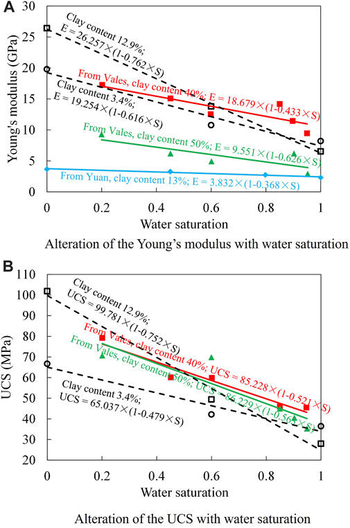
FIGURE 1. Alteration of geomechanical properties with water saturation (Experimental data cited from Yuan et al. (2014); and Valès et al. (2004); data with black blank symbols were data from this study). (A) Alteration of the Young’s modulus (B) Alteration of the UCS with water saturation with water saturation.
2.2 Theoretical calculation of the WIF propagation length
In the above section, the geomechanical properties can be updated based on water saturation. The relationship between geomechanical properties and water saturation can be described by Eq. 7 and the constants can be determined by experiments. Water saturation can calculated by the governing equations for the two-phase flow. In addition, substituting all these alternations, the distribution of stress and deformation in the rock can be obtained by the governing equation for rock deformation.
The stress intensity factor at fracture tip changes with the stress, which depends on the pressure inside the fracture and the in-situ stress around the fracture. According to the theory of linear elastic fracture mechanics (Pook, 2000), the fracture propagates when stress intensity factor is larger than the fracture toughness. The fracture stops propagating when the stress intensity factor decreases to the close to the fracture toughness.
To simplify the calculation of the stress intensity factor at the fracture tip, some assumptions were made as following:
(1) The rock deformation obeys the elasticity behavior. The plasticity behavior of rock is ignored because the area of plasticity domain around the fracture is much smaller compared with that of the WIF and thus (Lin et al., 2019a).
(2) The WIF are bi-wings, which are symmetric to the injection well.
(3) The in-situ stress in the vicinity of the WIF is symmetric to the injection well.
(4) The pressure inside the fracture (pf) remains the same along the whole WIF.
Assuming the initial length of WIF is 2L (L is the half length), the half WIF is divided into n segments, and the area beyond WIF can be divided into k segments according to the stress distribution.
According to the theory of fracture mechanics, the stress intensity factor at the WIF tip can be expressed as (Pook, 2000):
Owing to the stress concentration phenomenon at the WIF tip, stress distributions around the WIF are divided into n+k segments as shown in Figure 2. The in-situ stress at each segment can be expressed in a linear function if the segment is small enough, therefore, the in-situ stress of each segment can be expressed as follows (taking the right WIF domain as an example):
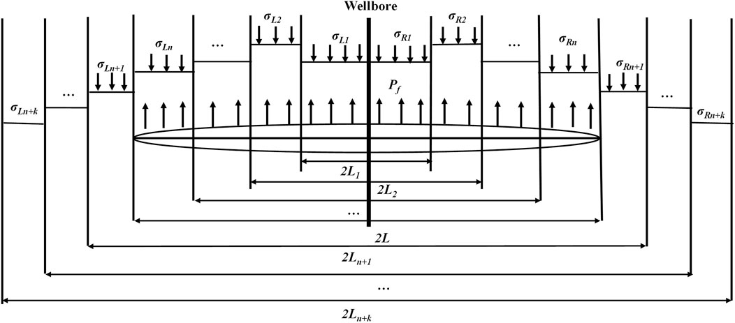
FIGURE 2. Schematic diagram of stress distribution along and beyond the fracture length.
The pressure inside the WIF (pf) is assumed as constant along the WIF. The net pressure in the ith segment (pi (x)) is expressed as follows:
Substituting Eq. 10 into Eq. 8, the expression of the stress intensity factor of the WIF can be obtained as follows:
If the stress intensity factor (KIA) obtained from Eq. 11 is larger than the fracture toughness (KIC), the WIF propagates into new domains. The additional in-situ stress is applied to the new WIF and the KIA decreases. When KIA decreases to KIC, the WIF stops to propagate. In this case, the relationship between the KIC and Ln+k (related to the new WIF length) can be expressed by Eq. 12. If the in-situ stress redistribution is known (all the parameters of Bi and ai are known), the only unknown variable in Eq. 12 is the Ln+k (related to the new WIF length). The new fracture length after WIF propagation can be obtained accordingly through the calculation of Ln+k as following.
2.3 Numerical modelling of the WIF propagation
The KIA at the WIF tip during the water-flooding was calculated through numerical simulations to investigate the impact of water-rock interaction on the WIF propagation. A 2D geometry model was established to represent the reservoir to simplify the calculation, as shown in Figure 3. The geometry size is 350m×200 m. There is one injection well and one production well located on the left and right boundary. Each well connects with one hydraulic fracture represented by the blue area in Figure 3. The reservoir is initially saturated with oil. No flow boundaries are applied on the up and down boundaries. Water is injected through the left hydraulic fracture (connecting to injection well) with a constant injection pressure. Oil is produced through the right hydraulic fracture (connecting to production well) with a constant production pressure. The maximum horizontal stress is parallel with the hydraulic fracture, while the minimum horizontal stress is applied vertical to the hydraulic fracture. The displacement vertical to boundary is fixed on both left and bottom boundaries (illustrated as the roller boundary condition in Figure 3). The parameters used in the following simulation cases are listed in Table 1. The reservoir in the Northwest China, that has the quick WIF propagation problem, has been developed since 1998. It is also a low-pressure reservoir and its formation pressure coefficient (ratio of pore pressure to hydrostatic pressure) is 0.7–0.9 and its average value is 0.77. The gradients of maximum horizontal stress and minimum horizontal stress are 18.5 MPa/km and 15.4 MPa/km, respectively. The average reservoir depth is 1300 m. The range of porosity is 7–15% and its average value is 10%. The range of permeability is 0.05–1.6mD and its average value is 0.1mD. Based on the compression test of rocks from this reservoir, the average values of Young’s modulus and Poisson’s ratio are 20 GPa and 0.2. Therefore, parameters in Table 1 were updated according to average values of reservoir’s properties. The maximum horizontal stress and minimum horizontal stress were set as 24 MPa and 20 MPa, respectively. Initial formation pressure was set as 10 MPa. Values of porosity and permeability were set as 10% and 0.3mD, respectively.
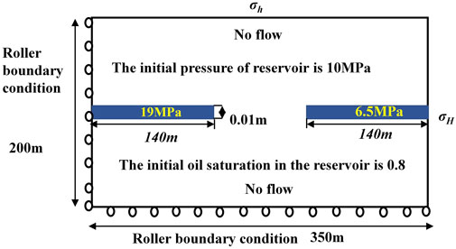
FIGURE 3. Geometry and initial boundary conditions of the numerical model.
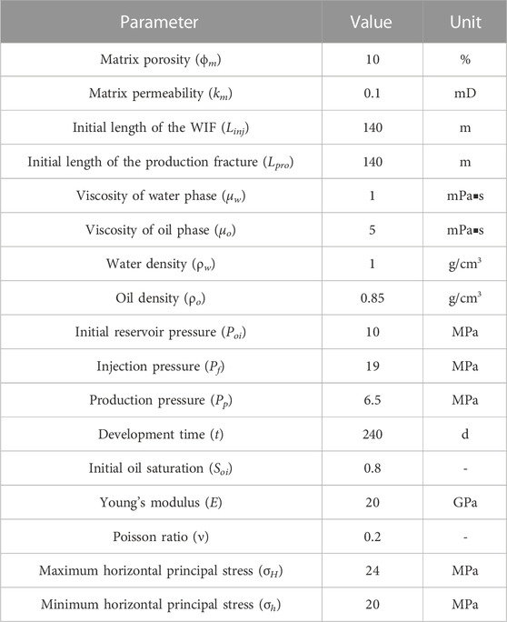
TABLE 1. Basic parameters for the cases of numerical simulation.
3 Model validation of the stress distribution induced by the WIF propagation
The WIF propagation depends on stress around fracture, therefore, the simulation solution of stress around fracture was validated. During waterflooding, water-rock interactions affect geomechanical properties and induce the heterogeneity of geomechanical properties. However, there is no theoretical solution of stress around a fracture for a reservoir with heterogeneity of geomechanical properties. Therefore, in this study, the simulation solution of stress around a fracture for a homogeneous reservoir was compared with theoretical solution proposed by Adachi et al. (2007) based on the elastic theory. If the simulation solution for the homogeneous reservoir is valid, it is highly possible that the simulation solution for the heterogeneous reservoir is proper.
The theoretical solution of stress distribution was calculated with the parameters listed in Table 1. The geometry size is 600m × 1000 m in order to compare with simulation and theoretical solutions. The numerical solution of the stress on two lines perpendicular to the WIF was calculated, and compared with the theoretical solution, as shown in Figure 4. Results indicate that the numerical solution is consistent with the theoretical solution within the distance from the center of the WIF to 10 L. The mean error between the numerical and theoretical solutions is 3.64%, indicating that numerical solution of the stress induced by the WIF is accurate. Consequently, the proposed model in this study is capable of effectively modeling the stress during the waterflooding process.
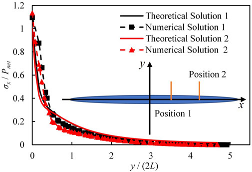
FIGURE 4. Comparison of the numerical and theoretical solutions of the stress distribution along two lines vertical to the fracture.
4 The impact of water-rock interaction on the WIF propagation
In this section, impacts of the injection pressure and damage variables on the WIF propagation were clarified. In addition, the critical injection pressure of the WIF propagation under different damage variables was investigated. Moreover, the sensitivity analysis of the effects of the fracture length of both production well and injection well on the WIF propagation were conducted and the reason of water influx in the extra-low permeability reservoir was discussed.
4.1 Impact of the injection pressure on the WIF propagation
During the oil displacement with waterflooding, the displacement efficiency would decrease if the WIF propagation increases rapidly. Therefore, the injection pressure should normally be controlled to attain proper WIF propagation. The impact of the injection pressure on the WIF propagation was investigated in this section with numerical simulations, in which the minimum horizontal stress was set as 20 MPa, and three injection pressure values of 19 MPa, 20 MPa and 21 MPa were assumed.
The distribution of stress in the y direction (σy, stress vertical to WIF) along the WIF under three different injection pressures is illustrated in Figure 5. In the case with the injection pressure of 19 MPa, the injection pressure is smaller than the minimum horizontal stress. The stress increases by approximately 4 MPa at the WIF tip due to the decrease in the WIF width and closure of the WIF around the fracture tip, as shown in Figure 5. In contrast, since the injection pressures are the same as and larger than the minimum horizontal stress in the other two cases, the fracture width increases and the WIF expands around the tip, inducing tensile stress and the decrease of the stress at the WIF tip, as shown in Figure 5. The decreasing magnitude of the stress at the WIF tip increases with the injection pressure, which specifically is approximately 2 MPa and 5 MPa as the injection pressure increases to 20 MPa and 21 MPa, respectively.
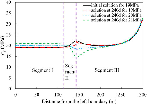
FIGURE 5. The σy distribution along the WIF.
The stress distribution can be divided into several segments to calculate the KIA and the alteration in the WIF length. The stress is roughly constant in the first segment, but varies in the other two segments, as shown Figure 5. Consequently, the slope of the stress in the first segment (a1) is assumed as 0, and the fracture length is within and beyond the initial WIF length in the second and third segment respectively. The three segments are representative to calculate the WIF propagation length. The stress variation behavior is assumed as linear behavior to simplify the calculation, as shown in Eq. 9. Parameters used in this equation are summarized in Table 2.
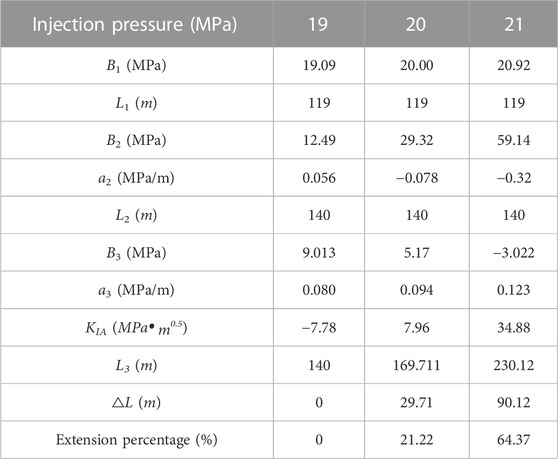
TABLE 2. Parameters and calculation results for the three cases with different injection pressures.
Substituting the parameters in Table 2 and the corresponding injection pressure into Eq. 11, the KIA values for the three cases can be obtained. After integration, the expression of KIA at the WIF tip can be expressed in Eq. 13.
In this section, the total length of the first and second segments is the same as the initial length of the WIF (L) and remains 140 m for the three cases. pf is the injection pressure, B1, B2 and a2 are constants for stress distribution which can be obtained by data fitting. The KIA is negative when the injection pressure is less than the minimum horizontal stress (20 MPa) and positive otherwise. The fracture toughness (KIC) is usually less than 1 MPa.m0.5. which is assumed as 0.42 MPa.m0.5 in this case. The WIF can propagate if only the injection pressure reaches and surpasses the minimum horizontal stress (20 MPa). This result is consistent with the common conclusion of hydraulic fracture propagation (Bryant Steven et al., 2003; Wang et al., 2019).
When the KIA at the WIF tip is larger than the KIC, the WIF propagates and the new WIF extends into the area of the third segment. The additional stress is applied at the new WIF and the KIA decreases. In the ideal situation, the new WIF stops to propagate until the updated KIA equals to the KIC. The expression of the updated KIA is shown in Eq. 14. The new WIF length (L3) can be figured out by assuming the value of the KIA equals to that of the KIC.
The calculation results of the KIA and other parameters are listed in Table 2. The WIF propagation length (△L) is denoted by the difference between the initial WIF length (L) and the updated WIF length (L3), which increases with the injection pressure. It is roughly 30 m with the injection pressure of 20 MPa, accounting for 21% of the initial WIF length, while it reaches up to 90 m as the injection pressure increases to 21 MPa, accounting for 64% of initial WIF length, indicating that the injection pressure should be carefully controlled to avoid the rapid WIF propagation.
4.2 Impact of damage variable on the WIF propagation
The impact of water-rock interactions was ignored in the above analysis of the WIF propagation. However, previous studies indicate that the long-term waterflooding triggers water-rock interactions and further triggers geomechanical property alternations.The clay contents of samples in Figure 1 is 13–50%, which can trigger an obvious property changes by water-rock interactions. Other study illustrated that the geomechanical property could drop by 50% after 50-day water immersion even if the clay content is only around 2% (Zhao et al., 2016). In addition, the clay content of sands in reservoirs used water-flooding is 4–20% and its average value is 10.4% as shown in Table 3. Obviously, the clay content magnitude lies between ones from references and the immersion time is usually over 300-day during water-flooding so that the impact of water-rock interaction on geomechanical properties for those rocks cannot be ignored during waterflooding.
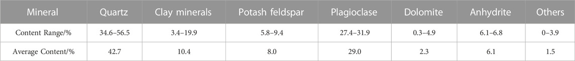
TABLE 3. Mineral content of sand rocks in a reservoir in Northwest China.
In this section, the impact of water-rock interactions on geomechancial property was represented by the damage variables proposed in the section 2.1.3, which can characterize the alterations of geomechanical properties such as Young’s modulus and Poisson’s ratio with water saturation. Eight groups of damage variable varying from 0 to 0.8 were set in different simulation cases and the updated geomechanical properties can be calculated with Eq. 7.
The distributions of σy along the WIF with different damage variables were studied under the condition that the minimum principal stress is larger than the injection pressure, as shown in Figure 6. The stress around WIF tip changes considerably when the water-flooding induces alteration of geomechanical property, and it decreases with the damage variable. The decreasing magnitude of the stress around the WIF tip increases with the damage variable. Specifically, the maximum decreasing magnitude of the stress reaches about 7 MPa when the damage variable is 0.5.
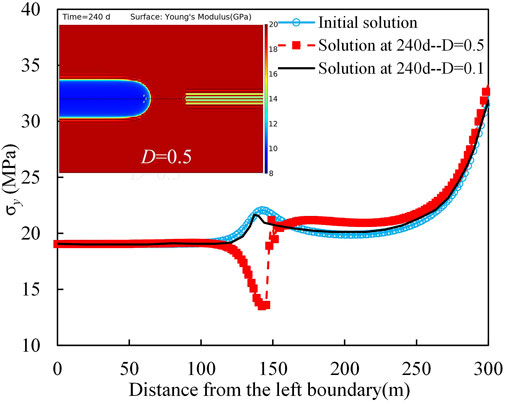
FIGURE 6. The σy distribution along the WIF with different damage variables(D).
The difference in the stress distribution among these cases results from the alteration of geomechanical property induced by water-rock interactions. According to the experimental results, there is a linear relationship between the geomechanical parameters of the rock and the water saturation. The water saturation changes drastically during the waterflooding in the area around the WIF after 240 days of waterflooding, which increases from the initial value of 0.2 to 0.7–0.9 while it remains unchanged in the other area of the reservoir. In consequence, the water saturation is unevenly distributed throughout the whole reservoir, leading to a non-uniform distribution of the rock geomechanical properties. Specifically, the Young’s modulus decreases from 20 GPa to 10 GPa in the area around the hydraulic fracture connecting with the injection well, resulting in the heterogeneity of the reservoir property, as shown by the top-left image in Figure 6. The stress distributions can also be divided into three segments, which can be fitted with Eq. 9. The parameters of the stress distributions are summarized in Table 4. According to Eq. 13, the KIA at the WIF tip is calculated. If the damage variable is under 0.3, the KIA is less than the KIC, and the WIF fails to propagate with an injection pressure of 19 MPa. Otherwise, the KIA turns to be larger than the KIC and the WIF propagates even though the injection pressure (19 MPa) is less than the minimum horizontal stress (20 MPa).
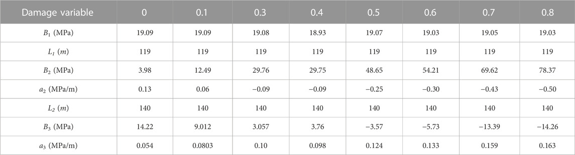
TABLE 4. Parameters of the stress distribution for cases of WIF with different damage variables.
The WIF propagation length induced by water-rock interactions can be obtained according to Eq. 14, and it increases rapidly with the damage variable but barely changes after 0.7, as illustrated in Figure 7. The WIF propagation length accounts for over 70% of the initial WIF length as the damage variable is over 0.7, indicating that the WIF can propagate instantly and may connect to the hydraulic fractures near the production well. The significant WIF propagation length results in sudden water influx, significantly reducing the efficiency of waterflooding in the extra-low permeability reservoir. Therefore, the injection pressure for the long-term waterflooding should be properly controlled to avoid the dramatical WIF propagation.
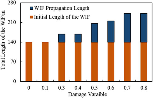
FIGURE 7. WIF propagation length with different damage variables.
4.3 Critical injection pressure for the WIF propagation under different damage variables
The WIF propagation length increases dramatically as the damage variable increases, demonstrating that the injection pressure should be reduced for a large damage variable. In this section, the critical injection pressure (Crp) inducing the WIF propagation was analyzed.
The critical injection pressure decreases with the damage variable in a quadratic function, as illustrated in Figure 8. It remains 20 MPa (as same as the minimum horizontal stress) with no rock damage considered, slightly decreases by 0.7 MPa as the damage variable reaches 0.3, and undergoes an abrupt decrease afterwards. The maximum decrease magnitude of critical injection pressure is nearly 3.8 MPa which accounts for 19% of the minimum horizontal stress. The decrease of critical injection pressure results from the reservoir heterogeneity induced by the waterflooding and water-rock interactions. This heterogeneity affects the stress distribution around the WIF tip and contributing to the WIF propagation under relatively low injection pressure.
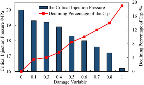
FIGURE 8. Critical injection pressure for the WIF propagation with different damage variable.
4.4 Effect of the fracture length on the WIF propagation
(a) fracture connecting to production well
The interaction between production fracture and injection fracture also affects the stress distribution around the WIF. In this section, the injection pressure is set as 19 MPa because the injection pressure is normally less than the minimum horizontal principal stress. The damage variable is assumed as 0.4. The other parameters and conditions are consistent with those presented in Table 1 and Figure 3.
The KIA and WIF propagation length increase with the production fracture length, as shown in Figure 9. The WIF fails to propagate as the production fracture length is less than 40 m. With the increase of production fracture length, the WIF can even propagate under the same injection pressure (19 MPa). Specifically, the WIF propagation length is approximately 30 m, accounting for 21% of the initial WIF length as the production fracture reaches at 140 m. If the production fracture is less than 40 m, the WIF would stop propagating. Although the WIF propagation length is not extraordinarily long, the increase in the production fracture length reduces the distance between the production and injection fracture, accelerates the WIF propagation and increases the risk of sudden water influx.
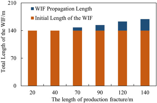
FIGURE 9. Effects of the initial length of the production fracture length on the WIF propagation.
(2) fracture connecting to injection well
The initial length of injection fracture also affects the stress distribution around the WIF. In this section, the injection pressure is set as 19 MPa and the production fracture length remains 140 m. Five groups of injection fracture length are set to demonstrate the effects of injection fracture length on WIF propagation.
The KIA and WIF propagation length increase with the production fracture length, as shown in Figure 10. With the increase of initial fracture length, the total length of the WIF propagation increases with an exponential function (y=53ⅹe0.0087x). The fracture length enhances the WIF propagation, which may result in serious water influx.
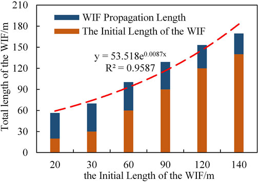
FIGURE 10. Effects of the initial length of the WIF on the WIF propagation.
5 Conclusion
Waterflooding is an efficient way to improve oil production for extra-low permeability reservoirs, which increases water saturation and induces water-rock interactions, resulting in the alteration of geomechanical properties. Early water breakthrough along the WIF may diminish the waterflooding efficiency and production performance due to the low swept volume, therefore, it is important to accurately capture the dynamic propagation of the WIF with controlling factors. In this study, A numerical model for the WIF propagation was proposed, coupled with fluid flow and rock deformation in the extra-low permeability oil reservoirs during the waterflooding process. The impact of water-rock interaction on the WIF propagation was analyzed with numerical simulations, and the stress distribution after waterflooding was demonstrated. In addition, based on the theory of fracture mechanics, the method to calculate the WIF propagation length was proposed. Moreover, the factors affecting the WIF propagation were discussed. Main conclusions were drawn as follows.
(1) The WIF propagation is highly sensitive to the injection pressure, which should be less than the minimum horizontal stress to avoid the rapid WIF propagation. If the injection pressure is as same as the minimum horizontal stress, the WIF propagation length increases dramatically and accounts for over 20% of the initial WIF length. Even if the injection pressure is only slightly larger than the minimum horizontal stress, the WIF propagation length can increase considerably and account for 64% of the initial WIF length.
(2) The alteration of geomechanics properties induced by water-rock interactions affects WIF propagation. Water-rock interactions induce alteration and heterogeneous distribution of geomechanics properties, decreasing the stress around the WIF and the stress intensity factor at the WIF tip. The WIF can propagate even though the injection pressure is less than the minimum horizontal stress after water-rock interactions. Specifically, the WIF propagation length can account for over 70% of the initial length when the decrease magnitude of Young’s modulus is 50%. The critical injection pressure can decrease by 15% of the minimum horizontal stress if the decrease magnitude of Young’s modulus is over 80%.
(3) Apart from the injection pressure and the alteration of geomechanics properties, the initial fracture length also affects WIF propagation. The WIF propagation length increases with the initial fracture length whereas the magnitude is less than the one from water-rock interactions.
Data availability statement
The original contributions presented in the study are included in the article/supplementary material, further inquiries can be directed to the corresponding author.
Author contributions
HQ: Conceptualization; Methodology; Formal Analysis, Writing—Original Draft; Funding acquisition YP: Conceptualization; Formal Analysis, Software; Investigation; Writing—Review & Editing; Supervision; Funding acquisition XX: Methodology; Validation; Investigation; Writing—Original Draft; ZP: Writing—Review & Editing; Supervision FZ: Supervision; Resources.
Funding
This work is supported by the National Natural Science Foundation of China (Grant No. 52174044, 52004302), Science Foundation of China University of Petroleum, Beijing (No. ZX20200134, 2462021YXZZ012), and the Strategic Cooperation Technology Projects of CNPC and CUPB (ZLZX 2020-01-07).
Conflict of interest
The authors declare that the research was conducted in the absence of any commercial or financial relationships that could be construed as a potential conflict of interest.
Publisher’s note
All claims expressed in this article are solely those of the authors and do not necessarily represent those of their affiliated organizations, or those of the publisher, the editors and the reviewers. Any product that may be evaluated in this article, or claim that may be made by its manufacturer, is not guaranteed or endorsed by the publisher.
References
Adachi, J., Siebrits, E. M., Peirce, A., and Desroches, J. (2007). Computer simulation of hydraulic fractures. Int. J. Rock Mech. Min. Sci. 44 (5), 739–757. doi:10.1016/j.ijrmms.2006.11.006
Baker, R., Dieva, R., Jobling, R., and Lok, C. (2016). “The myths of waterfloods, EOR floods and how to optimize real injection schemes,” in SPE Improved Oil Recovery Conference.
Bennion, B., and Bachu, S. (2008). Drainage and imbibition relative permeability relationships for supercritical CO2/brine and H2S/brine systems in intergranular sandstone, carbonate, shale, and anhydrite rocks. SPE Reserv. Eval. Eng. 11, 487–496. doi:10.2118/99326-pa
Brochard, L., Vandamme, M., and Pellenq, J. M. (2012). Poromechanics of microporous media. J. Mech. Phys. Solids 60 (4), 606–622. doi:10.1016/j.jmps.2012.01.001
Bryant Steven, L., Paruchuri Ramoj, K., and Prasad, S. K. (2003). Flow and solute transport around injection wells through a single, growing fracture. Adv. Water Resour. 26 (8), 803–813. doi:10.1016/s0309-1708(03)00065-4
EIA (2018). Tight oil remains the leading source of future U.S. crude oil production. 02-22. Avaialable at: https://www.eia.gov/todayinenergy/detail.php?id=35052.
Erguler, Z. A., and Ulusay, R. (2009). Water-induced variations in mechanical properties of clay-bearing rocks. Int. J. Rock Mech. Min. Sci. 46 (46), 355–370. doi:10.1016/j.ijrmms.2008.07.002
Fan, T., Song, X., Wu, S., Li, Q., Wang, B., Li, X., et al. (2015). A mathematical model and numerical simulation of waterflood induced dynamic fractures of low permeability reservoirs. Petrol. explor. Dev. 42, 541–547. doi:10.1016/s1876-3804(15)30047-1
Gadde, P. B., and Sharma, M. M. (2001). “Growing injection well fractures and their impact on waterflood performance,” in Paper presented at the SPE Annual Technical Conference and Exhibition, New Orleans, LA, September, 2001. doi:10.2118/71614-MS
Hagoort, J. (1981). Waterflood-induced hydraulic fracturing. Rijswijk: civil engineering & geosciences.
Hustedt, B., Zwarts, D., Bjoerndal, H. P., Masfry, R., and Hoek, P. J. (2008). Induced fracturing in reservoir simulations: Application of a new coupled simulator to a waterflooding field example. SPE Res Eval Eng 11 (03), 569–576. doi:10.2118/102467-pa
Li, H., Yang, Z. J., Li, B. B., and Wu, J. Y. (2021). A phase-field regularized cohesive zone model for quasi-brittle materials with spatially varying fracture properties[J]. Eng. Fract. Mech. 2021 (17), 107977.
Lin, Q., Wan, B., Wang, Y., Lu, Y., and Labuze, J. F. (2019a). Unifying acoustic emission and digital imaging observations of quasi-brittle fracture. Theor. Appl. Fract. Mech. 103, 102301. doi:10.1016/j.tafmec.2019.102301
Ling, S., Wu, X., Sun, C., Liao, X., Ren, Y., and Li, X. (2016). Experimental study of chemical damage and mechanical deterioration of black shale due to water-rock chemical action. J. Exp. Mech. 31 (4), 511–524.
Ma, T., and Chen, P. (2014). Study of meso-damage characteristics of shale hydration based on CT scanning technology. Petroleum Explor. Dev. 41 (2), 249–256. doi:10.1016/s1876-3804(14)60029-x
Meng, M., Ge, H., Ji, W., Wang, X., and Chen, L. (2015). Investigation on the variation of shale permeability with spontaneous imbibition time: Sandstones and volcanic rocks as comparative study. J. Nat. Gas Sci. Eng. 27, 1546–1554. doi:10.1016/j.jngse.2015.10.019
Nazir, A., Singh, P. K., Peng, C. P., Shiralkar, G. s., Moschovidis, Z. A., and Baack, W. L. (1994). Injection-above-parting-pressure waterflood pilot, valhall field, Norway. SPE Reserv. Eng. 9 (01), 22–28. doi:10.2118/22893-pa
Peng, Y., Liu, J., Pan, Z., and Connell, L. D. (2015). A sequential model of shale gas transport under the influence of fully coupled multiple processes. J. Nat. Gas Sci. Eng. 27, 808–821. doi:10.1016/j.jngse.2015.09.031
Peng, Y., Liu, J. S., Pan, Z. J., Connell, L. D., Chen, Z., and Qu, H. Y. (2017). Impact of coal matrix strains on the evolution of permeability. Fuel 189, 270–283. doi:10.1016/j.fuel.2016.10.086
Peng, Y., Liu, J. S., Pan, Z. J., Qu, H. Y., and Connell, L. D. (2018). Evolution of shale apparent permeability under variable boundary conditions. Fuel 215, 46–56. doi:10.1016/j.fuel.2017.11.024
Peng, Y., Liu, J. S., Zhang, G., Pan, Z., Hou, Y., Wang, Y., et al. (2021). A pore geometry-based permeability model for tight rocks and new sight of impact of stress on permeability. J. Nat. Gas Sci. Eng. 91 (9), 103958. doi:10.1016/j.jngse.2021.103958
Perkins, T. K., and Gonzalez, J. A. (1985). The effect of thermoelastic stresses on injection well fracturing. Soc. Petroleum Eng. J. 25 (01), 78–88. doi:10.2118/11332-pa
Pook, L. P. (2000). Linear elastic mechanics for engineers: Theory and application. Southampton: WIT press.
Qu, H. Y., Peng, Y., Pan, Z. J., Zhou, F. J., and Zhang, K. (2019). A fully coupled simulation model for water spontaneous imbibition into brittle shale. J. Nat. Gas Sci. Eng. 66, 293–305. doi:10.1016/j.jngse.2019.03.028
Shi, B., Xia, B., Lin, Y., and Xu, J. (2012). CT imaging and mechanicm analysis of crack development by hydration in hard-brittle shale formations. Acta pet. sin. 33 (1), 137–142.
Suarez-Rivera, R., Stenebr Ten, J., Gadde, P. B., and Sharma, M. M. (2002). “An experimental investigation of fracture propagation during water-floodingwater-flooding,” in International symposium & exhibition on formation damage control.
Suri, A., and Sharma, M. (2007). “A model for water-floodingwater-flooding into frac-packed wells,” in SPE Annual Technical Conference and Exihibition Anahelm, California, USA.
Suri, A., Sharma, M. M., and Moreno, J. M. (2010). “Injectivity of frac-packed wells: A case study of the guando field,” in Paper presented at the SPE International Symposium and Exhibition on Formation Damage Control, Lafayette, LA, February, 2010. doi:10.2118/125897-MS
Valès, F., Minh, D. N., Gharbi, H., and Rejeb, A. (2004). Experimental study of the influence of the degree of saturation on physical and mechanical properties in Tournemire shale (France). Appl. Clay Sci. 26, 197–207. doi:10.1016/j.clay.2003.12.032
Vásárhelyi, B., and Ván, P. (2006). Influence of water content on the strength of rock. Eng. Geol. 84 (1–2), 70–74. doi:10.1016/j.enggeo.2005.11.011
Wang, J. G., and Peng, Y. (2014). Numerical modeling for the combined effects of two-phase flow, deformation, gas diffusion and co2 sorption on caprock sealing efficiency. J. Geochem. Explor. 144, 154–167. doi:10.1016/j.gexplo.2013.12.011
Wang, L., Bornert, M., Héripré, E., Chanchole, S., Pouya, A., and Halphen, B. (2015). Microscale insight into the influence of humidity on the mechanical behavior of mudstones. J. Geophys. Res. Solid Earth 120 (5), 3173–3186. doi:10.1002/2015jb011953
Wang, L. L., Bornert, M., Héripré, E., Yang, D. S., and Chanchole, S. (2014). Irreversible deformation and damage in argillaceous rocks induced by wetting/drying. J. Appl. Geophys. 107 (8), 108–118. doi:10.1016/j.jappgeo.2014.05.015
Wang, W., Peng, H., Li, G., Yu, T., and Wei, C. (2019). Waterflooding and optimum displacement pattern for ultra-low permeability reservoirs. Oil Gas Geol. 40 (1), 182–189.
Wang X., X., Dang, H., and Gao, T. (2018). Method of moderate water injection and its application in ultra-low permeability oil reservoirs of Yanchang Oilfield, NW China. Petrol. explor. Dev. 45, 1094–1102. doi:10.1016/s1876-3804(18)30112-5
Wang, Y. J., Song, X. M., Li, J. H., Hui, G., Liu, P., and Wang, X. J. (2018). Heterogeneity on dynamic fracture, internal configuration of compound sand body and significance to the development of ultra-low permeability reservoir in Erdos Basin (In Chinese). J. Northwest Univ. 48 (1), 123–131.
Wang, Y. J., Song, X. M., Tian, C. B., Shi, C. F., Li, J. H., Hui, G., et al. (2015). Dynamic fractures are an emerging new development geological attribute in water-flooding development of ultra-low permeability reservoirs. Petroleum Explor. Dev. 42 (2), 247–253. doi:10.1016/s1876-3804(15)30012-4
Warpinski, N. R., Clark, J. A., Schmidt, R. A., and Huddle, C. W. (1982). Laboratory investigation on the-effect of in-situ stresses on hydraulic fracture containment. Soc. Petroleum Eng. J. 22 (03), 333–340. doi:10.2118/9834-pa
Wen, H., Chen, M., Jin, Y., Zhang, Y., Ge, W., Du, J., et al. (2015). Water activity characteristics of deep brittle shale from Southwest China. Appl. Clay Sci. 108, 165–172. doi:10.1016/j.clay.2015.02.015
Yew, C. H., and Liu, G. H. (1993). Fracture tip and Critical Stress intensity factor of a hydraulically induced fracture. SPE Prod. Facil. 8 (03), 171–177. doi:10.2118/22875-pa
Yuan, W., Li, X., Pan, Z., Connell, L. D., Li, S., and He, J. (2014). Experimental investigation of interactions between water and a lower Silurian Chinese shale. Energy & Fuels 28, 4925–4933. doi:10.1021/ef500915k
Zhao, Z., Yang, J., Zhang, D., and Peng, H. (2016). Effects of wetting and cyclic wetting–drying on tensile strength of sandstone with a low clay mineral content. Rock Mech. Rock Eng. 50 (2), 485–491. doi:10.1007/s00603-016-1087-9
Zhu, W. C., and Wei, C. H. (2011). Numerical simulation on mining-induced water inrushes related to geologic structures using a damage-based hydromechanical model. Environ. Earth Sci. 62 (1), 43–54. doi:10.1007/s12665-010-0494-6
Zwarts, D., Hustedt, B., and Hoek, P. J. (2006). “Modelling induced fracture mechanics in reservoir simulations – a new coupled simulator,” in ECMOR X - 10th European Conference on the Mathematics of Oil Recovery.
Nomenclature
ai first constant to fit the stress data
Bi second constant to fit the stress data
C a certain geomechanical property
D damage variable
E Young’s modulus of rock
f body force, N/m3
G shear modulus of rock,GPa
km matrix permeability, mD
krwm relative permeability for water phase
krom relative permeability for oil phase
KIA stress intensity factor, MPa.m0.5
L the half-length of the WIF,m
No constant in oil relative permeability expression
Nw constant in water relative permeability expression
pc capillary pressure, MPa
pm pore pressure, MPa
p(x) net pressure inside the WIF, MPa
pom oil pressure, MPa
pwm water pressure,MPa
pe entry capillary pressure, MPa
qw source term for water, kg/m3/s
qo source term for oil, kg/m3/s
Swm water saturation
Som oil saturation
Sor irreducible saturation for oil
Swr irreducible saturation for water
u displacement, m
αm Biot’s coefficients
λ pore size distribution index
v Poisson’s ratio
σRi stress of the ith segment,MPa
φm reservoir porosity, %
ρw water density, kg/m3
ρo oil density, kg/m3
Keywords: extra-low permeability oil reservoir, waterflooding, water-flood-induced fracture, water-rock interaction, fracture propagation ∗
Citation: Qu H, Peng Y, Pan Z, Xu X and Zhou F (2023) Numerical study on the impact of water-rock interactions on the propagation of water-flooding induced fracture. Front. Earth Sci. 11:1129913. doi: 10.3389/feart.2023.1129913
Received: 22 December 2022; Accepted: 17 January 2023;
Published: 26 January 2023.
Edited by:
Tianshou Ma, Southwest Petroleum University, ChinaReviewed by:
Houbin Liu, Southwest Petroleum University, ChinaGang Lei, China University of Geosciences Wuhan, China
Copyright © 2023 Qu, Peng, Pan, Xu and Zhou. This is an open-access article distributed under the terms of the Creative Commons Attribution License (CC BY). The use, distribution or reproduction in other forums is permitted, provided the original author(s) and the copyright owner(s) are credited and that the original publication in this journal is cited, in accordance with accepted academic practice. No use, distribution or reproduction is permitted which does not comply with these terms.
*Correspondence: Yan Peng, eWFuLnBlbmdAY3VwLmVkdS5jbg==