 Zhenhua Ouyang
 Gen Li
 Qiong Wang2*
95% of researchers rate our articles as excellent or good
Learn more about the work of our research integrity team to safeguard the quality of each article we publish.
Find out more
ORIGINAL RESEARCH article
Front. Earth Sci. , 21 March 2023
Sec. Geohazards and Georisks
Volume 11 - 2023 | https://doi.org/10.3389/feart.2023.1128697
This article is part of the Research Topic Mine Engineering Geological Disaster Forecasting, Monitoring, and Prevention – Volume II View all 7 articles
It is hard to control roadways effectively with a heightened burst risk using conventional support techniques, which may cause burst fatalities in the coal mine. Thus, an in-situ modification method, which involves artificially constructing a cracked zone and a reinforced zone, was proposed to improve the stability of the roadways with heightened burst risk. This paper investigated the efficiency to non of the in-situ modification method in improving burstroadway safety by performing a physical experiment. The results of the experiment indicated that the dynamic stress was obviously reduced in the modified roadway. Accordingly, the influence factors of the in-situ modification method were explored using numerical simulation. It was found that the thickness and the degree of damage to the cracked zone were key governing factors in reducing energy and improving roadway stability. The energy dissipation value increased as the thickness and the degree of damage to the cracked zone increased but showed a slower growth trend when the thickness and the degree of damage to the cracked zone increased to a certain value. In addition, the high sensitivity to dynamic load was found in parts of the roadway side exhibiting a larger stress reduction rate even with thinner cracked zone thickness and a lower degree of damage. This research provides an effective and economical method for coal roadways with heightened burst risk.
Coal burst is always one of the most severe threats to miners especially in deeper and strong burst risk coal mines (Mark, 2016). In recent years, a number of coal burst fatalities have been reported in various countries (Patyñska and Kabiesz, 2009; Liu et al., 2019; Cai et al., 2020; Shi et al., 2021). With the increasing depth of coal mining, coal extraction is facing ever-increasing stress conditions with an acute occurrence and frequency of coal burst cases. As mining conditions become rather complex, having a clear understanding of factors contributing to coal burst, triggering mechanisms, control strategies, and realizing spatial-temporal forecasting is extremely difficult (Cai et al., 2019).
Historically, research suggests that the contributing factors associated with a heightened burst risk were high stress, depth of cover, thick sandstone roof, and seam rolling and pitching (Hoelle, 1989; Maleki, 1995; Alber et al., 2008; Maleki et al., 2011). Under the coupling effect of these factors, various hypotheses on the burst mechanism relating to strength, stability, stiffness, burst liability, energy, and superposition of static-dynamic stresses have been proposed in the past several decades (Kidybinski, 1980; Romashov and Tsygankov, 1993; Linkov, 1996; Xu and Cai, 2017a; He et al., 2017; Ma et al., 2018).
Based on the burst mechanism, the three physical parameters of stress, strain, and energy are considered important indexes of controlling coal bursts. Several studies argued that controlling stress is the key to reducing burst risk. Corresponding studies proposed burst-control strategies in different engineering conditions (Qi et al., 2013; Pan et al., 2014; Zhang and Jiang, 2020), but in recent years, more scholars have attempted to establish the connection between energy and controlling burst. In terms of energy absorption, various innovative support structures characterized by larger deformation were developed such as energy-absorbing bolts (cables) (Anders, 2005; Charette and Plouffe, 2007; Simser and Andrieux, 2007; Varden et al., 2008; He and Guo, 2014), high-power hydraulic devices (Ma et al., 2014; Wang and Zhang, 2019; Wang et al., 2020), and retractable steel sheds (Zhao et al., 2014; Gao et al., 2021). These innovative supporting structures have greatly improved the safety of the burst roadway; however, in coal-extraction activities, the failure of these supporting structures and the occurrence of burst hazards were inevitable in the face of a more complex mining environment. Thus, from the perspective of energy dissipation, it has been suggested that the resistance of burst roadways can be improved by increasing the degree of crack in the surrounding rock (Wang and Pan, 2015; Xu and Cai, 2017b). Previous studies identified the importance of cracked surrounding rock in burst prevention, and they studied the energy-absorption characteristics of the cracked zone generated by in-situ stress in coal roadways. However, for heightened burst-risk roadways, it is hard for the natural cracked zone formed by in-situ stress to resist the powerful burst energy effectively. Until now, few attempts were made to develop a systematic method by constructing a cracked zone artificially in a heightened burst-risk roadway. Therefore, this work presents an in-situ modification method by artificially constructing a cracked zone and a reinforced zone to improve the stability of a heightened burst-risk roadway. A set of physical experiments and numerical simulations were carried out to verify the efficiency of the proposed method associated with an analysis of the dynamic response and energy dissipation. Additionally, we explored the factors influencing this innovative method.
Previous research (Xu and Cai, 2017b; Yi et al., 2021) has established that the cracked zone existing in the roadway can optimize the stress distribution of surrounding rocks. Therefore, an in-situ modification method, which is done by artificially constructing a cracked zone and a reinforced zone in a coal burst roadway, is proposed to improve the stability of roadways with heightened burst risk. The method intends to use multi-times blasting, supercritical carbon dioxide, or hydrofracturing technology to increase the degree of crack in the surrounding rock of the roadway while simultaneously adopting the short-hole grouting technique to strengthen the surface rocks of the roadway. The coal burst roadway reconstructed by the in-situ modification method contains a reinforced zone, a cracked zone, and an intact zone, as shown in Figure 1.
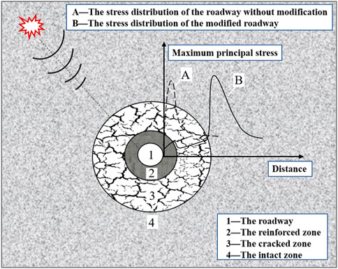
FIGURE 1. The surrounding rock structure of the modified roadway with in-situ modification method.
Compared with the unmodified roadway, the advantages of the modified roadway by the in-situ modification method are that more dynamic energy is absorbed and the stress status of the surrounding rock is improved (Yi et al., 2021). As plotted in Figure 1, curve A is the stress distribution of the roadway before modification, and curve B is the stress distribution of the roadway after modification. Comparatively, the existence of the cracked zone in a modified roadway exerts an obvious influence on the response of surrounding rock stresses. Before modification, the vertical stress first increases and then decreases to the in-situ stress, which indicates that there is an obvious concentration of stress in the surrounding rock near the unmodified roadway. In contrast, after modification, there is a significant drop in the vertical stress in the surrounding rock near the roadway, and the area of stress concentration is located on the outside of the cracked region. This means the degree of concentration of the elastic energy is reduced in the modified roadway by the in-situ modification method, and, as a result, the possibility ofrock burst can be eliminated to some extent by a decrease in peak stress value and enlarged bearing areas of elastic energy.
Thus, the roadway modified by the in-situ modification method provides a double guarantee for coal burst resistance. One guarantee is that the artificial cracked zone transfers stress concentration far away from the roadway side and absorbs the dynamic energy of surrounding rocks, and the other is that the reinforced zone plays a role in enhancing the overall strength of the roadway.
The selected I010203 panel of the Kuangou coal mine is located near the city of Hutubi, Xinjiang Province, China. The panel belongs to the B2 coal seam with a mean buried depth of 480 m and a mean thickness of 11.8 m. The lithology of the rock layers near the B2 coal seam is shown in Figure 2. To obtain the physico-mechanical parameters of the rock mass near the B2 coal seam, some specimens taken from the Kuangou coal mine were tested in the laboratory. Young´s modulus, Poisson´s ratio was obtained from uniaxial compression tests. The Triaxial compression tests were carried out to obtain cohesion and fiction angle, and the tensile strength was determined by Brazilian Splitting tests. The detailed physico-mechanical parameters of rock mass are listed in Table 1.
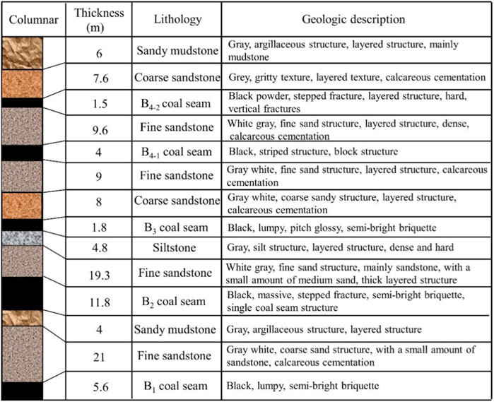
FIGURE 2. Thelithology of the rock layers near the B2 coal seam.
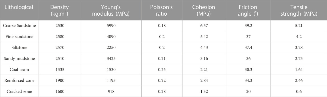
TABLE 1. Physico-mechanical parameters of rock mass near the I01023 panel.
In light of the dimensional similitude principle, the density (ρ), geometric length (l), and elastic modulus (E) were selected as the fundamental dimensions. The similarity ratios of ρ, l, and E were defined as 1.5:1, 100:1, and 1:1 based on the ratio of the physical model’s prototype. As the prototype and physical model existed in the same acceleration field, the ratio of acceleration (a) was determined to be 1:1. Subsequently, the similarity ratios of displacement (δ), stress (σ), cohesion (C), friction angle (φ), strain (ε), Poisson´s ratio (υ), speed (V,) time (t), damping (ζ), force (F), and energy (e) were calculated, as listed in Table 2.
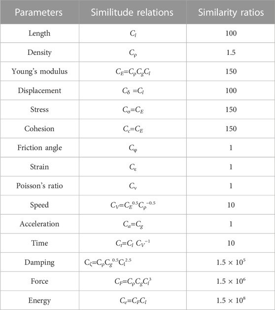
TABLE 2. The similarity coefficient for the physical model experiments.
The mixtures of river sand, slaked lime, plaster, and water were used as similar materials to simulate the rock layers near the B2 coal seam and artificial regions around the roadway. In the starter phase, a series of consolidation tests and orthogonal tests were carried out to confirm whether the proportions of the similar material corresponds with the similarity coefficient. Both the physical models with an unmodified roadway and a modified roadway were constructed in the experiments, as shown in Figure 3A. The dimensions of the physical models were 1.2 m high, 2 m wide, and 0.3 m thick; the roadways were arranged in the B2 coal seam with a radius of 20 mm. For the physical model with a modified roadway, the thickness of the reinforced zone and the cracked zone constructed by the in-situ modification method were 10 mm and 50 mm, respectively. In the physical model B, the reinforced zone was made of similar material as the coal seam but with a higher proportion of 3wt% plaster and less river sand to achieve approximately 30% increment in elastic modulus, and the cracked zone was modeled with 14wt% plastic particle to simulate the cracks and to reduce the elastic modulus by approximately 60% in comparison to the intact rock.
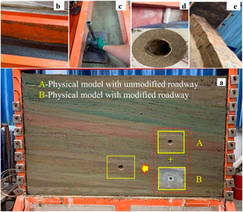
FIGURE 3. The physical models with an unmodified roadway and a modified roadway. (A) integral physical model, (B) placing a layer of black foam, (C) compacting the similar materials, (D) using a concentric configuration to model the cracked zone and reinforced zone, (E) appling the iro blocks on model top.
In the physical model experiments, the modeling procedures of physical model A with unmodified roadway and the physical model B with modified roadway were as follows:
(1) First, a layer of black foam was placed around the inner wall of the model experiment platform to eliminate the knock-on effect of the rebound of dynamic waves on the platform border, as displayed in Figure 3B.
(2) Next, the similar materials of each rock layer and artificial regions of the roadway were prepared based on similar material proportions obtained by a preliminary test. Accordingly, to avoid many voids in the model, similar materials were compacted gently layer by layer, as shown in Figure 3C.
(3) Then, when it came to modeling the roadway, different construction methods were adopted for two different types of roadways. For the unmodified roadway, a polyvinyl chloride (PVC) tube with an outer diameter of approximately 40 mm was inserted into the corresponding layer. After the whole model was finished, the PVC tube was slowly pulled out to simulate the unmodified roadway. For the modified roadway, a concentric configuration was used to model the cracked zone and reinforced zone. As shown in Figure 3D, from the inside to the outside, the concentric configuration was done by successively inserting a PVC tube with a diameter of 40 mm and two cylinders coated with an aluminum sheet with a diameter of 60 mm and 80 mm. The similar materials of the cracked zone and the reinforced zone were filled in corresponding regions of the concentric configuration to preform the modified roadway. After the whole model was finished, the PVC tubes and aluminum sheet were pulled out eventually.
(4) Finally, the iron blocks with the equivalent weight of the overburden layer were applied on top of the model to simulate the overlying pressure, as shown in Figure 3E.
The dynamic load applied to the physical model was simulated by the free fall impact of a steel ball. In the experiments, to simulate the strong impact effect of the roadway with heightened burst risk, a steel ball with a weight of 50 N fell freely from a height of 0.1 m to produce the effect of the dynamic energy of approximately 5 J. which is equivalent to the dynamic energy of 7.5 × 10⁸ J in a coal mine. The dynamic stress was monitored by pressure sensors embedded at the different positions (top, side, and bottom) around the roadway. The locations and numbers of the monitoring points are shown in Figure 4.
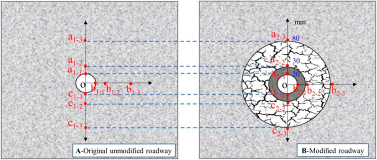
FIGURE 4. Stress monitoring point layout of the physical model with (A) original unmodified roadway, (B) modified roadway.
The dynamic stress-time curves of the monitoring points in the unmodified roadway were plotted, as shown in Figure 5. Figure 5A shows that the dynamic peak stresses of a1-1, a1-2, and a1-3 at the top of the unmodified roadway are 4.74, 3.96, and 6.57 MPa. In addition, it can be seen from Figure 5B that the dynamic peak stresses of b1-1, b1-2, and b1-3 at the side of the unmodified roadway are 8.48, 19.86, and 11.17 MPa. Figure 5C shows that the dynamic peak stresses of c1-1, c1-2, and c1-3 at the bottom of the unmodified roadway are 4.62, 3.07, and 4.24 MPa, respectively.
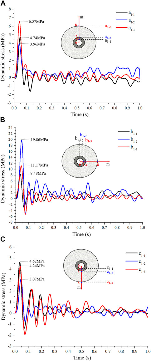
FIGURE 5. The vertical dynamic stress-time curves of monitoring points located at (A) roadway top, (B) roadway side, and (C) roadway bottom in the unmodified roadway.
The dynamic stress-time curves of the monitoring points in the modified roadway are shown in Figure 6. Compared with the data in Figure 5, it is apparent that the dynamic stresses in the modified roadway are much smaller than that in the unmodified roadway. As shown in Figure 6, after the dynamic wave passed through the cracked zone, the dynamic peak stress at the top of the roadway decreased from 6.52 MPa to 0.17 MPa with a stress reduction of 97.4%. The dynamic peak stresses at the side of the roadway decreased from 21.66 MPa to 0.047 MPa, and the dynamic peak stresses at the bottom of the roadway decreased from 6.78 MPa to 0.063 MPa resulting in a stress reduction of 98–99%. However, as the dynamic wave passed through the reinforced zone, there was a slight rise in the value of the dynamic peak stress. The dynamic peak stress at the top, side, and bottom of the modified roadway increased from 0.17 MPa to 0.86 MPa, 0.047 MPa–1.15 MPa, and 0.063 MPa–0.83 MPa, respectively. From the above data obtained by physical model experiments, this study identified a clear benefit of the cracked zone in reducing the dynamic stress of the roadway.
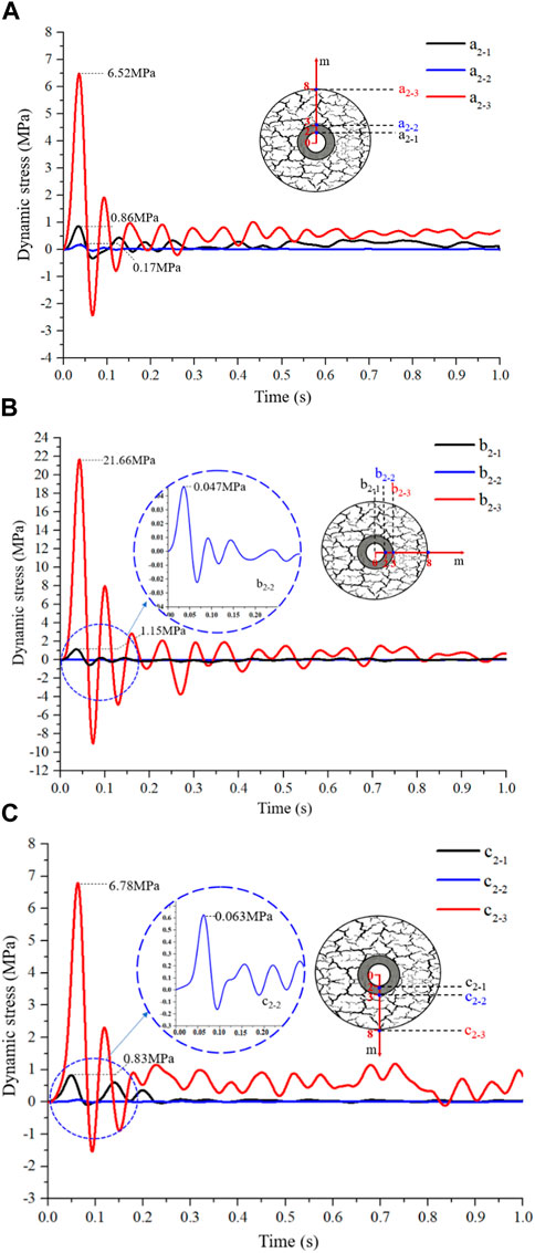
FIGURE 6. The vertical dynamic stress-time curves of monitoring points located at (A) roadway top, (B) roadway side, and (C) roadway bottom in the modified roadway.
In contrast to the monitoring points in the unmodified roadway, dynamic peak stresses of the monitoring points between the cracked zone and the intact zone had different changing values at different positions of the roadway. There had been a slight decrease (approximately 0.76%) in the dynamic peak stress at the top of the roadway; however, there had been a sharp increase in the dynamic peak stress at the side and bottom of the roadway with increases of 93.91% and 59.91%, respectively These results indicated that a reflection effect of the dynamic wave was inclined to occur at the side and bottom of the modified roadway, comparatively. Taken together, after the dynamic wave passed through the cracked zone, the dynamic peak stress of all positions of the modified roadway decreased by more than 95%. At the side of the modified roadway in particular, the decrease of the dynamic peak stress reached 99.76%. Then, when the dynamic waves traveled through the cracked zone to the reinforced zone, the dynamic peak stress showed a smaller increase at each position of the modified roadway. In general, the dynamic peak stress of the modified roadway shows a considerable decrease of more than 80% compared with the unmodified roadway.
The LS-DYNA is a finite element software for non-linear dynamic analysis that is intrinsically capable of studying problems such as high-speed collision, impact, and explosion. Therefore, the numerical model of the I010203 panel was used to investigate the influential factors of the modified roadway with the in-situ modification method, as shown in Figure 7. The dimensions selected for the model were 200 m long, 180 m wide, and 50 m high, and boundary conditions with no reflection effect was set up around the model. According to the measured in-situ stress of the B2 coal seam, a horizontal stress of 6 MPa and a vertical stress of 7.5 MPa were applied to the model, and the model’s horizontal sides and bottom were roller constrained. Because the study objects were centered on the surrounding rock of the roadway, the area of interest around the roadway was discretized into triangular blocks with an average edge length of 0.25 m, while the remainder of the model were divided into triangular blocks and the triangular blocks were progressively graded with an increasing edge length (1 m, 1.5 m, 2 m) at a distance from the roadway to avoid a sudden large increase in grid size, which would have adversely affected the modeling accuracy.
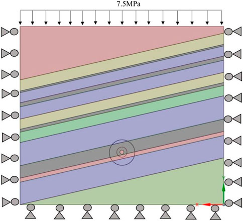
FIGURE 7. Schematic diagram of the numerical model.
In the model, the HJC (Holmquist-Johnson-Cook) model was used to simulate the behavior of the cracked zone. The HJC model is a constitutive model that can describe material damage and can be used to calculate large deformation of materials at high strain rates. The HJC model can be expressed as:
Where
The damage D of the HJC model is accumulated from the equivalent plastic strain and plastic volumetric strain, which is expressed as:
Where
Additionally, the Mohr-Coulomb model was used to simulate the behavior of the remaining rocks. The Mohr-Coulomb model can describe the response of the brittle materials to normal stress as well as shear stress. The Mohr-Coulomb model can be expressed as:
Where τ is the shear strength; σ is the normal stress; φ is the angle of internal friction, and C is the cohesion.
In order to ensure the accuracy of the mechanical parameters of the rock layers in the numerical model, a correction model (with diameter×height =5 m × 10 m) of coal rock was established to subject the uniaxial compression test. The mechanics parameters of the model were defined by the correction model and laboratory tests. In numerical simulations, the influence factors of the thickness of the cracked zone, the degree of damage to the cracked zone, and the thickness of the reinforced zone were selected as research objects to determine the dynamic mechanical behavior of the modified roadway. Accordingly, seven numerical models with different conditions were constructed, and the detailed parameters of each model are shown in Table 3. To record the dynamic stress of the modified roadway in the numerical simulation, the monitoring points were arranged at different positions around the modified roadway. The detailed layout and numbering of monitoring points are shown in Figure 8.
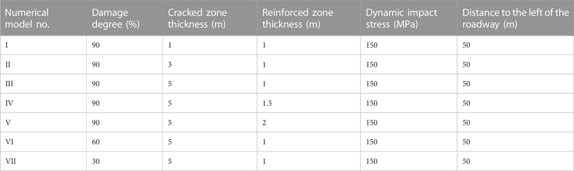
TABLE 3. The detailed parameters of the numerical models.
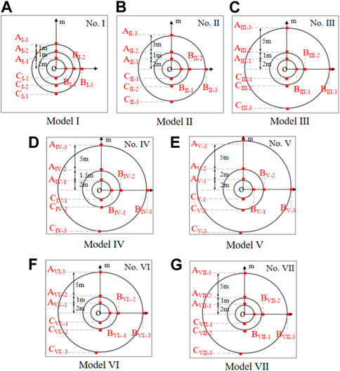
FIGURE 8. The monitoring points’ layout and numbering in (A) model I, (B) model II, (C) model III, (D) model IV, (E) model V, (F) model VI and (G) model VII
Previous studies (Zhu et al., 2016) have shown that the dynamic load induced by roof collapse can be analyzed by P-wave, and P-wave (Wang et al., 2017) can be expressed by Equation (5). In light of previous studies (Guo et al., 2017; Wang et al., 2017; Wang et al., 2018), the in-situ parameters of dynamic load in numerical models are listed in Table 4.
where A0 is the impulse amplitude;

TABLE 4. The parameters of dynamic load.
The dynamic peak stresses of the monitoring points in numerical models were extracted, as shown in Table 5. From Table 5, the dynamic response of the modified roadway in different conditions can be compared. Before the dynamic wave passes through the cracked zone, the dynamic peak stress of the monitoring points between the cracked zone and intact zone is much higher, especially in the positions of the side of the roadway, which exceeded 200 MPa in each numerical model. However, there was a significant drop in the dynamic peak stress after the dynamic wave passed through the cracked zone. As in model-Ⅰ, the dynamic peak stresses at the top, side, and bottom of the modified roadway show a considerable decrease of 52.03 MPa–31.70 MPa, 220.55 MPa–0.63 MPa, and 62.36 MPa to 1.19, respectively. These results demonstrated again that the cracked zone exerts a significant influence on the dynamic mechanical behavior of the modified roadway. Simultaneously, a slight rise in the dynamic peak stress was observed after the dynamic wave passed through the reinforced zone. The results obtained by numerical simulations were entirely consistent with the results of physical experiments.
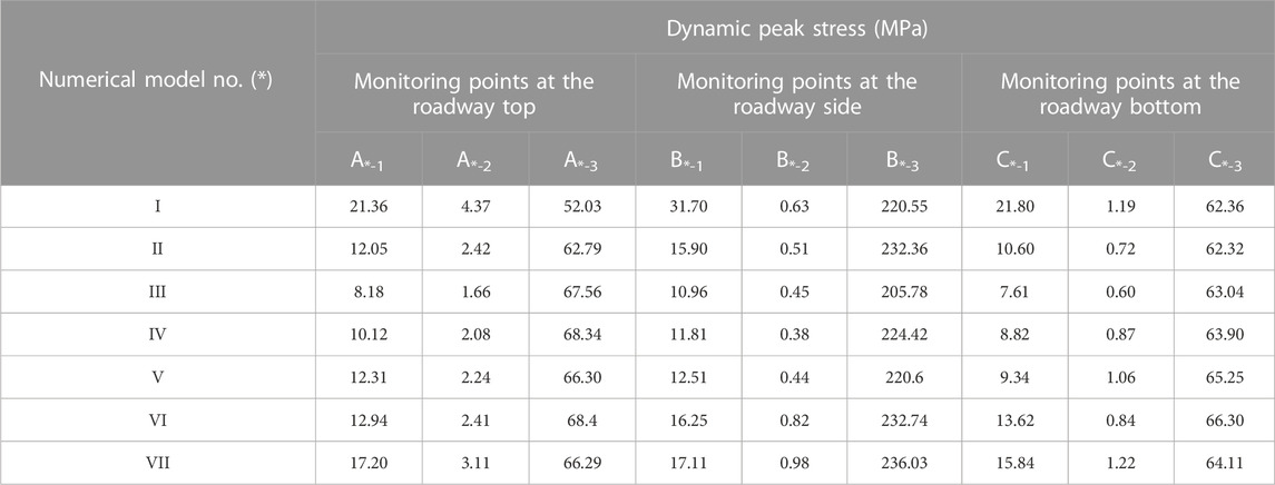
TABLE 5. Dynamic peak stress monitored in different numerical models.
(1) Influence of the cracked zone thickness
The state of dynamic stresses with different thicknesses of the cracked zone was studied in the numerical simulations. As shown in Figure 9, the dynamic stress-time curves of different cracked zone thicknesses (1 m, 3 m, 5 m) were seen. At the top of the roadway, corresponding to the cracked zone thickness of 1 m, 3 m, and 5 m, the dynamic peak stresses of the monitoring points located at the inner wall were 21.36, 12.05, and 8.18 MPa with a reduction of 58.9%, 80.8%, and 87.9% compared with the dynamic peak stresses of the monitoring points between the cracked zone and the intact zone. Concurrently, at the side of the roadway, the dynamic peak stresses of the monitoring points located at the inner wall were 31.70, 15.90, and 10.96 MPa, respectively, which showed a decrease of 85.6%, 93.2%, and 94.7% with the cracked zone thicknesses of 1 m, 3 m, and 5 m. Accordingly, at the bottom of the roadway, the dynamic peak stresses decreased from 62.36 MPa to 21.80 MPa, 62.32 MPa–10.60 MPa, and 63.04 MPa–7.61 MPa with a decrease of 65.0%, 81.7%, and 87.9%, respectively. These results indicated that the reduction of dynamic stress increased with the increase in the cracked zone thickness, but the reduction rate of dynamic stress is likely to decline when the cracked zone thickness increases above 3 m.
(2) Influence of the reinforced zone thickness
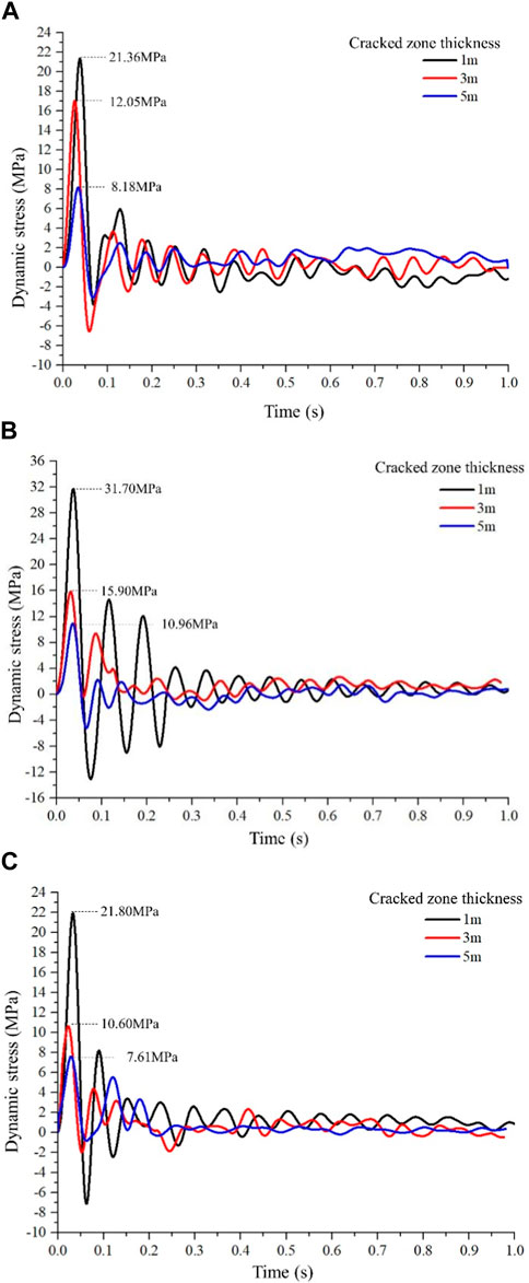
FIGURE 9. Dynamic stresses with different cracked zone thicknesses for monitoring points located at the inner wall of (A) roadway top, (B) roadway side, and (C) roadway bottom.
In the conditions of 5 m cracked zone thickness and 90% degree of damage, the state of dynamic stress with different reinforced zone thicknesses was studied. As shown in Figure 10, dynamic stress-time curves of different reinforced zone thicknesses (1 m, 1.5 m, and 2 m) were seen. Under the conditions of the reinforced zone thickness of 1 m, 1.5 m, and 2 m, the dynamic peak stresses of monitoring points located at the inner wall of the roadway top were 8.18 MPa, 10.12 MPa, and 12.31 MPa, with a decrease of 87.9%, 85.2%, and 81.4%, respectively. For the monitoring points located at the inner wall of the roadway side, the dynamic peak stresses with reinforced zone thickness of 1 m, 1.5 m, and 2 m were 10.96 MPa, 11.81 MPa, and 12.51 MPa, which showed a decrease of 94.7%, 94.7%, and 94.3%. Simultaneously, at the bottom of the roadway, the reduction rates of dynamic peak stresses showed a decrease of 65.0%, 81.7%, and 87.9%, corresponding to the reinforced zone thickness of 1 m, 1.5 m, and 2 m, respectively. The results indicated that the influence of the reinforced zone thickness on the method was not obvious if the cracked zone has a competent energy absorption capacity.
(3) Influence of the degree of damage to the cracked zone
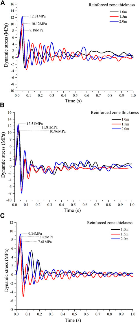
FIGURE 10. Dynamic stresses with different reinforced zone thicknesses for monitoring points located at the inner wall of (A) roadway top, (B) roadway side, and (C) roadway bottom.
In conditions of the cracked zone thickness of 5 m and reinforced zone thickness of 1 m, the state of dynamic stress with different reinforced zone thicknesses was studied. As shown in Figure 11, the dynamic stress-time curves with different cracked zone degrees of damage (30%, 60%, 90%) were seen. When the degrees of damage to the cracked zone were 90%, 60%, and 30%, the dynamic peak stresses of monitoring points located at the inner wall of the top of the roadway were 12.31 MPa, 12.94 MPa, and 17.20 MPa, which decreased by 87.9%, 81.1%, and 74.1%. Accordingly, there was a decrease of 94.7%, 93.0%, and 92.7% for the monitoring points located at the inner wall of the roadway side, and there was a decrease of 87.9%, 79.5%, and 75.3% at the bottom of the roadway. This indicated that the degree of damage to the cracked zone has a significant impact on the distribution of dynamic stress of the modified roadway. As the degree of damage to the cracked zone increased, the reduction rates of dynamic stress increased. There was also a significant difference in dynamic response at different positions of the modified roadway. The dynamic responses of the roadway side were extremely sensitive to the degree of damage to the cracked zone; even with the cracked zone thickness of 1 m and the degree of damage of 30%, the reductions of dynamic stress were greater than 92%. In contrast to the roadway side, the dynamic responses of the roadway top and roadway bottom exhibited a lower energy absorption capacity in conditions of a smaller thickness and degree of damage to the cracked zone.
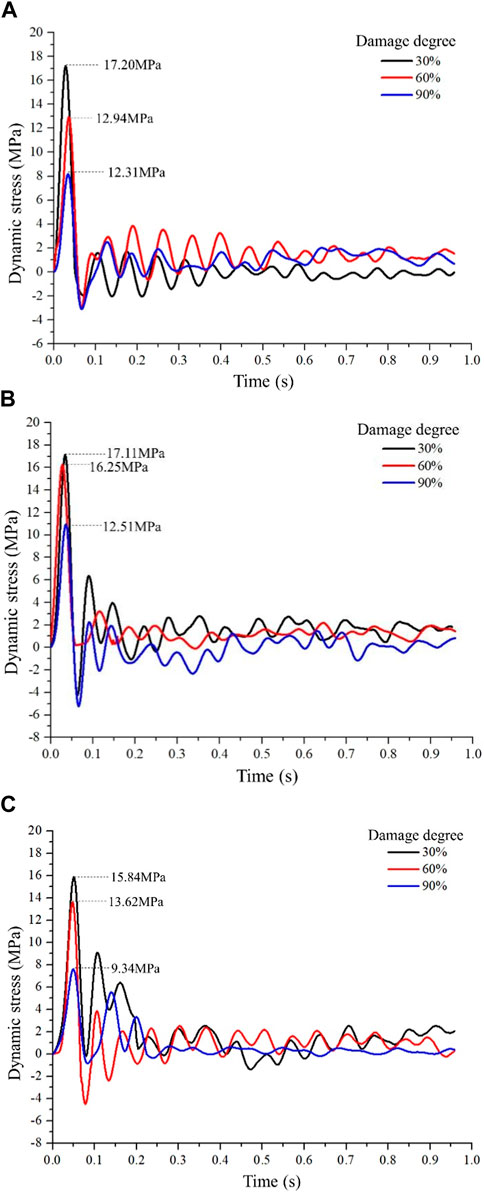
FIGURE 11. Dynamic stresses with different degrees of damage to the cracked zone for monitoring points located at the inner wall of (A) roadway top, (B) roadway side, and (C) roadway bottom.
The energy dissipation rates of the modified roadway in different conditions were summarized in Table 6. It can be seen from Table 6 that the energy dissipation rates of the cracked zone in all models were above 82%, which means the energy dissipation increased enormously in the modified roadway. In general, the energy dissipation of different regions in the modified roadway is presented asroadway top> roadway side> roadway bottom. Additionally, the energy dissipation increased as the thickness and the degree of damage to the cracked zone increased, but it was weakly affected by the thickness of the reinforced zone. Taking the energy dissipation of the area of the roadway top as an analytical object, it showed that when the cracked zone thickness was 1 m, 3 m, and 5 m, the corresponding energy dissipation rates were 93.56%, 97.65%, and 99.48%. When the degree of damage to the cracked zone was 30%, 60%, and 90%, the corresponding energy dissipation rates were 89.57%, 92.97%, and 99.48%. When the reinforced zone thickness was 1 m, 1.5 m, and 2 m, the energy dissipation rates were 99.48%, 99.54%, and 99.51%, which indicated that the influence of the reinforced zone thickness on the energy dissipation was not obvious.
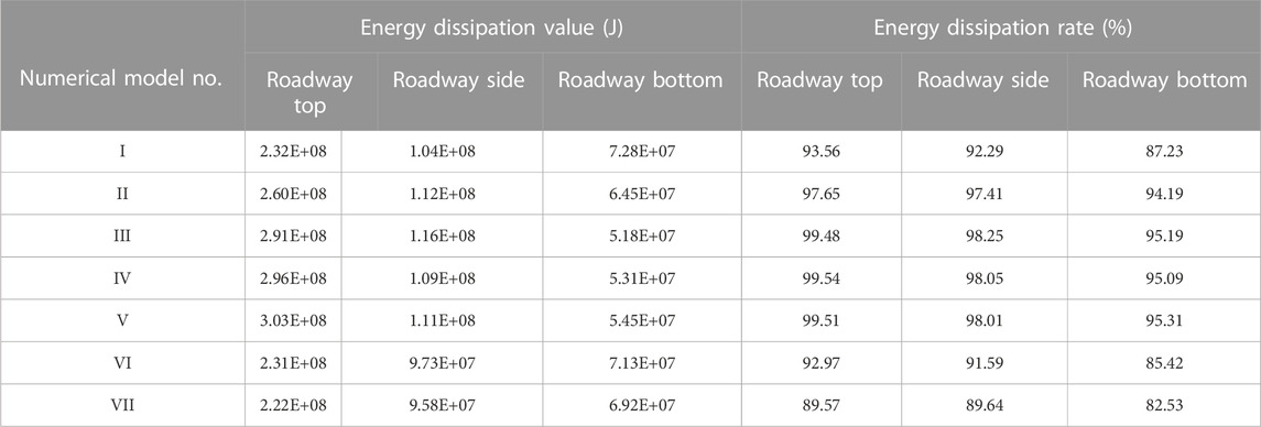
TABLE 6. The energy dissipation value and rate of the modified roadway with different conditions.
To explain the above research results, a mechanical model was constructed, as shown in Figure 12. In the mechanical model, the original surrounding rocks were supposed to be isotropic elastic materials and followed the Hoek-Brown failure criterion. A dynamic disturbance source induced by roof caving, a static stress of
FIGURE 12. The mechanics model for (A) overall, (B) intact zone, and (C) cracked zone in a modified roadway.
Based on the elastic and plastic theory, when the surrounding rock of the roadway is subjected to static load, the normal stress
Based on Eq. 6, it can be deduced that:
At the interface between the intact zone and the cracked zone (
where
Combined with Eqs 7–9, the abutment pressure of the cracked zone to the intact zone can be calculated as:
Substituting Eq. 8 into Eq. 4, the radial stress and tangential stress of the element in the intact zone are obtained as:
For the cracked zone of the modified roadway, the stress relation of rock element has an expression of:
Combined with Eq 9 and Eq 12, and the boundary condition of
Then, another expression of the normal stress and tangential stress of the element in the cracked zone can be obtained by the conditions of
Therefore, the support resistance of the reinforced zone applied to the cracked zone under static load was deduced as:
Additionally, if the dynamic load induced by roof caving is considered as well, the impact stress of the element on the interface between the cracked zone and the reinforced zone is:
where Ps is the initial stress of the impact source, d is the distance from the impact source to center point O of the roadway, η0 is the energy decay index of the impulse wave passed through the intact zone, and
Under the combined action of static and dynamic loads, the total stress produced on the interface between the reinforced zone and the cracked zone can be expressed as:
Assuming the ultimate bearing capacity of the modified roadway support system is
According to Eq. 18, two effective methods are provided to improve the impact resistance of the modified roadway. One efficient method is to improve the ultimate bearing capacity Pu of the modified roadway. An alternative method is to reduce the total stress
This paper proposed an in-situ modification method by artificially constructing a cracked zone and a reinforced zone in a heightened burst risk roadway. Based on physical experiments, the dynamic responses of the unmodified and modified roadway were analyzed. The results showed that the cracked zone constructed by the in-situ modification method had a significant effect on reducing the burst risk of roadway in the coal mine. In the modified roadway, the dynamic peak stress decreased by more than 95% after the dynamic waves passed through the cracked zone, and the dynamic stress reduction rate at the roadway side is the highest. However, a slight rise was observed in the dynamic peak stress after the dynamic wave passed through the reinforced zone. Overall, compared with the unmodified roadway, the total reduction rates of dynamic peak stress in the modified roadway were more than 80%.
The influence factors of the in-situ modification method were analyzed by a set of numerical simulations. The results showed that (1) the reduction of dynamic stress (or dynamic energy) increased with the increase of cracked zone thickness but showed a declining trend in the reduction rate when the cracked zone thickness is greater than 3 m. (2) The larger the degree of damage to the cracked zone the better the energy absorption effect of the modified roadway. Both the stress reduction value of the roadway top, side, and bottom increased as the degree of damage to the cracked zone increased. Additionally, there were regional variation differences of dynamic stress under different conditions. The dynamic responses of the roadway side were extremely sensitive to the degree of damage to the cracked zone; even with the degree of damage of 30%, the stress reduction is greater than 90%. However, the dynamic responses of other positions exhibited a lower energy-absorption capacity in conditions of smaller thickness and degree of damage to the cracked zone. (3) In the condition of a cracked zone with a competent energy-absorption capacity, changing the thickness of the reinforced zone has a slight influence on the dynamic state of the modified roadway.
The original contributions presented in the study are included in the article/Supplementary Material, further inquiries can be directed to the corresponding author.
All the authors contributed to this paper. ZO. provided theoretical and methodological guidance in the research process.GL and QW prepared and edited the manuscript. GL, HY, ZL, and QS partially participated in literature search and data processing.
This research was supported by the National Natural Science Foundation of China (grant number 51974125), the National Natural Science Foundation of Hebei Province, China (grant number E2020508002), and the Special Fund of Basic Research and Operating of North China Institute of Science & Technology (grant number 3142018001).
We are grateful to China University of Mining and Technology for providing us with the experimental platform and all the reviewers for their specific comments and suggestions.
The authors declare that the research was conducted in the absence of any commercial or financial relationships that could be construed as a potential conflict of interest.
All claims expressed in this article are solely those of the authors and do not necessarily represent those of their affiliated organizations, or those of the publisher, the editors and the reviewers. Any product that may be evaluated in this article, or claim that may be made by its manufacturer, is not guaranteed or endorsed by the publisher.
Alber, M., Fritschen, R., Bichofff, M., and Meier, T. (2008). Rock mechanical investigations of seismic events in a deep longwall coal mine. Int. J. Rock Mech. Mine Sci. 46 (2), 408–420.
Anders, A. (2005). Laboratory testing of a new type of energy absorbing rock bolt. Tunn. Undergr. Space Technol. 20 (4), 291–300. doi:10.1016/j.tust.2004.12.001
Cai, W., Bai, X., Si, G., Cao, W., Gong, S., and Dou, L. (2020). A monitoring investigation into rock burst mechanism based on the coupled theory of static and dynamic stresses. Rock Mech. Rock Eng. 53 (12), 5451–5471. doi:10.1007/s00603-020-02237-6
Cai, W., Dou, L. M., Si, G. Y., Cao, A., Gong, S., Wang, G., et al. (2019). A new seismic-based strain energy methodology for coal burst forecasting in underground coal mines. Int. J. Rock Mech. Min. Sci. 123, 104086. doi:10.1016/j.ijrmms.2019.104086
Charette, F., and Plouffe, M. “Roofex-results of laboratory testing of a new concept of yieldable tendon,” in Proceedings of the 4th International Seminar on Deep and High Stress Mining, Perth, Australia, March 2007 (Australian Centre for Geomechanics), 395–404.
Gao, M., He, Y., Xu, D., and Yu, X. (2021). A new theoretical model of rock burst-prone roadway support and its application. Geofluids 2021 (8), 1–11. doi:10.1155/2021/5549875
Guo, W. Y., Zhao, T. B., Tan, Y. L., Yu, F. H., Hu, S. C., and Yang, F. Q. (2017). Progressive mitigation method of rock bursts under complicated geological conditions. Int. J. Rock Mech. Min. Sci. 96, 11–22. doi:10.1016/j.ijrmms.2017.04.011
He, J., Dou, L. M., Gong, S. Y., Li, J., and Ma, Z. (2017). Rock burst assessment and prediction by dynamic and static stress analysis based on micro-seismic monitoring. Int. J. Rock Mech. Mine Sci. 93, 46–53. doi:10.1016/j.ijrmms.2017.01.005
He, M. C., and Guo, Z. B. (2014). Mechanical property and engineering application of anchor bolt with constant resistance and large deeformation. Chin. J. rock Mech. Eng. 33 (7), 214–221. doi:10.13722/j.cnki.jrme.2014.07.001
Hoelle, J. “Coal bumps in an Eastern Kentucky coal mine 1989 to 1997,” in Proceedings of the 27th international conference on ground control in mining, Morgan-town, WV, USA, July 2008 (West Virginia University), 14–19.
Kidybinski, A. (1980). Bursting liability indices of coal. Int. J. Rock Mech. Min. Sci. Geomechanics Abstr. 17, 167–171. doi:10.1016/j.ijrmms.2008.07.014
Linkov, A. (1996). Rockbursts and the instability of rock masses. Int. J. Rock Mech. Min. Sci. Geomechanics Abstr. 33 (7), 727–732. doi:10.1016/0148-9062(96)00021-6
Liu, F., Tang, C., Ma, T., and Tang, L. (2019). Characterizing rockbursts along a structural plane in a tunnel of the hanjiang-to-weihe river diversion project by microseismic monitoring. Rock Mech. Rock Eng. 52 (6), 1835–1856. doi:10.1007/s00603-018-1649-0
Ma, T. H., Tang, C. A., Tang, S. B., Kuang, L., Yu, Q., Kong, D. Q., et al. (2018). Rockburst mechanism and prediction based on microseismic monitoring. Int. J. Rock Mech. Minine Sci. 110, 177–188. doi:10.1016/j.ijrmms.2018.07.016
Ma, X., Pan, Y. S., and Xiao, Y. H. (2014). Study on application of the mine anti-impact and energy-absorption device. Appl. Mech. Mater. 470, 598–603. doi:10.4028/www.scientific.net/AMM.470.598
Maleki, H. “An analysis of violent failure in u.s. coal mines: Case studies,” in Proceedings of the Mechanics and Mitigation of Violent Failure in Coal and Hard-Rock Mines, Special Publication, Washington, DC, USA, May 1995, 1–95.
Maleki, H., Rigby, S., McKenzie, J., and Faddies, T. “Historic mine designs and operational practices used in deep mines for controlling coal bumps,” in Proceedings of the 45th US rock mechanics/ geomechanics symposium, Alexandria, VA, USA, June 2011 (American Rock Mechanics Association), 11–276.
Mark, C. (2016). Coal bursts in the deep longwall mines of the United States. Int. J. Coal Sci. Technol. 3 (1), 1–9. doi:10.1007/s40789-016-0102-9
Pan, Y. S., Xiao, Y. H., and Li, Z. H. (2014). Study of support theory of rock burst in coal mine and its application. J. China Coal Soc. 39 (2), 222–228. doi:10.13225/j.cnki.jccs.2013.2015
Patyñska, R., and Kabiesz, J. (2009). Scale of seismic and rock burst hazard in the Silesian companies in Poland. Mine Sci. Technol. 19 (5), 604–608. doi:10.1016/s1674-5264(09)60112-5
Qi, Q. X., X L, Li, and Zhao, S. K. (2013). Theory and practices on stress control of mine pressure bumping. Coal Sci. Technol. 41 (6), 1–5. doi:10.1007/s13369-017-3056-3
Romashov, A., and Tsygankov, S. S. (1993). Generalized model of rock bursts. J. Mine Sci. 28 (5), 420–423. doi:10.1007/bf00711122
Simser, B., and Andrieux, P. “Field behaviour and failure modes of modified conebolts at the Craig, LaRonde an Brunswick mines in Canada,” in Proceedings of the Australian Centre for Geomechanics, Québec City, Canada, January 2007, 347–354.
Shi, Q. W., Pan, J. F., Wang, S. W., Liu, S., Mishra, B., and Seitz, S. (2021). Field monitoring of delayed coal burst in an advancing entry of a deep coal mine. Min. Metallurgy Explor. 38, 2417–2431. doi:10.1007/s42461-021-00508-6
Varden, R., Lachenicht, R., and Player, J. “Development and implementation of the garford dynamic bolt at the kanowna belle mine,” in Proceeidngs of the 10th underground operators conference, Launceston, Australia, January 2008, 14–19.
Wang, G. F., Li, G., Dou, L. M., Mu, Z. L., Gong, S. Y., and Cai, W. (2020). Applicability of energy-absorbing support system for rockburst prevention in underground roadways. Int. J. Rock Mech. Min. Sci. 132, 104396. doi:10.1016/j.ijrmms.2020.104396
Wang, J., and Zhang, J. (2019). Research on high-power and high-speed hydraulic impact testing machine for mine anti-impact support equipment. Shock Vib. 2019, 1–12. doi:10.1155/2019/6545980
Wang, K. X., and Pan, Y. S. (2015). An undified theory of energy absorption and anti-impact for surrounding rock and support in coal burst mine. Rock Soil Mech. 36 (9), 2585–2590. doi:10.16285/j.rsm.2015.09.019
Wang, P., Jiang, L. S., Jiang, J. Q., and Wei, L. (2018). Strata behaviors and rock burst–inducing mechanism under the coupling effect of a hard, thick stratum and a normal fault. Int. J. Geomechanics 2 (18), 04017135. doi:10.1061/(ASCE)GM.1943-5622.0001044
Wang, Z., Dou, L., Li, J., Kang, K., and Feng, L. (2017). Numerical investigation of damage risks of roadway surrounding rocks under oblique incident dynamic loads. Shock Vib. 2017 (2), 1–13. doi:10.1155/2017/6298372
Xu, Y. H., and Cai, M. (2017). Influence of strain energy released from a test machine on rock failure process. Can. Geotech. J. 55 (6), 777–791. doi:10.1139/cgj-2017-0256
Xu, Y. H., and Cai, M. (2017). Influence of strain energy released from a test machine on rock failure process. Can. Geotechnical J. 55 (6), 777–791. doi:10.1139/cgj-2017-0256
Yi, H. Y., Ouyang, Z. H., Zhou, X. X., Li, Z., Chen, J., and Li, K. (2021). Study on the modification of confining rock for protecting coal roadways against impact loads from a roof stratum. Minerals 11, 1331. doi:10.3390/min11121331
Zhang, M., and Jiang, F. (2020). Rock burst criteria and control based on an abutment-stress-transfer model in deep coal roadways. Energy Sci. Eng. 8, 2966–2975. doi:10.1002/ese3.715
Zhao, S., Ouyang, Z., and Li, X. “Theory and application of rock burst prevention based on rigid-flexible integrated support with energy absorbing,” in Proceedings of the 2014 International Conference on Mechanics and Civil Engineering (icmce-14), Amsterdam, Netherlands, December 2014 (Atlantis Press).
Keywords: coal burst, modifying the surrounding rock, cracked zone, energy absorption, influence factors
Citation: Ouyang Z, Li G, Wang Q, Yi H, Li Z and Shi Q (2023) An in-situ modification method for coal roadways with heightened burst risk. Front. Earth Sci. 11:1128697. doi: 10.3389/feart.2023.1128697
Received: 21 December 2022; Accepted: 09 February 2023;
Published: 21 March 2023.
Edited by:
Jie Chen, Chongqing University, ChinaReviewed by:
Ju Ma, Central South University, ChinaCopyright © 2023 Ouyang, Li, Wang, Yi, Li and Shi. This is an open-access article distributed under the terms of the Creative Commons Attribution License (CC BY). The use, distribution or reproduction in other forums is permitted, provided the original author(s) and the copyright owner(s) are credited and that the original publication in this journal is cited, in accordance with accepted academic practice. No use, distribution or reproduction is permitted which does not comply with these terms.
*Correspondence: Qiong Wang, d2FuZ3Fpb25nQG5jaXN0LmVkdS5jbg==
Disclaimer: All claims expressed in this article are solely those of the authors and do not necessarily represent those of their affiliated organizations, or those of the publisher, the editors and the reviewers. Any product that may be evaluated in this article or claim that may be made by its manufacturer is not guaranteed or endorsed by the publisher.
Research integrity at Frontiers
Learn more about the work of our research integrity team to safeguard the quality of each article we publish.