 Zhinan Hu
 Hongtao Mao
 Lixin Zhang2*
94% of researchers rate our articles as excellent or good
Learn more about the work of our research integrity team to safeguard the quality of each article we publish.
Find out more
ORIGINAL RESEARCH article
Front. Earth Sci., 01 February 2023
Sec. Environmental Informatics and Remote Sensing
Volume 11 - 2023 | https://doi.org/10.3389/feart.2023.1127078
This article is part of the Research TopicAdvances in Development and Utilization of Underground SpaceView all 17 articles
The connection of subway stations to surrounding underground spaces inevitably involves opening construction in the existing underground structure. The opening construction can strongly impact the existing underground structure when there is no reserved condition. In this study, three-dimensional numerical simulation, model test, and theoretical analysis are used to analyze the mechanical behaviors of side wall opening construction in a mined excavation subway station-Xuanwumen Station of Beijing Subway Line 4. Based on the deformation and stress characteristics of the existing side wall structure, two different reinforcement measures are compared. It is found that the vertical and horizontal deformations of the existing structure caused by opening construction is −1.58 and −1.79 mm, respectively, which are lower than the subway deformation control requirements (3 mm). However, the first and third principal stress increments are 2.14 and −4.62 MPa, respectively, which are markedly higher than the control requirement (10%). A “two-step opening” method is proposed for side wall opening construction in underground structures based on the solution of complex function to the orifice problem. This theoretical method is validated by numerical simulations and model tests, achieving highly consistent results. The allowable ultimate span of side wall opening is 5.75 m without reinforcement. Findings of the present study provide a reference for the design and construction of side wall openings in similar underground spaces.
Connections are an essential way for the development of urban underground space from isolated points to an interconnected underground space network (Wallace and Ng, 2016; Zhao and Künzli, 2016). When a subway station is connected to the surrounding underground space, it often involves the demolition of existing structural openings. The construction of opening in existing subway stations leads to stress redistribution in the station structure. In particular, when there are no reserved openings, improper construction can affect the function and structural safety of the station (Yin and Zhang, 2018; Yin et al., 2020).
Extensive research has been conducted on the opening in aboveground building structures and excavation of underground caverns. With respect to the opening in aboveground buildings, model tests and theoretical analyses (Zhang et al., 2019) were conducted to explore opening-induced changes in the mechanical properties of existing building walls (Moon et al., 2020), deep beams (Ahmed et al., 2020), rigid plates (Saad-Eldeen et al., 2018), and arched steel beams (Zaher et al., 2018). In addition, studies of mine roadways or tunnel mechanics investigated the deformation (Jia et al., 2014; Li et al., 2020), plastic zone distribution (Abdellah, 2017; Kong et al., 2022), and dynamic characteristics (Aydan, 2019) of surrounding rock caused by deep underground cavern excavation.
As for the openings in the subway station structure, the construction technology of subway station side wall openings, interface waterproofing, and deformation monitoring were reported. Sun et al. (2014) analyzed the stress characteristics of existing structure during opening construction of side wall and propounded corresponding countermeasures for the new and existing structure interfaces. Wu and Yan. (2017) introduced the key points of opening construction in subway station connecting aisle and discussed the waterproof treatments of interface. Liu et al. (2018) obtained the maximum vertical displacement generated by opening construction based on site monitoring. In terms of mechanical properties, some studies mainly involved the stress characteristics, seismic responses, and theoretical model analysis of shear wall with reserved opening. Nassernia and Showkati. (2017) examined the mechanical behaviors of tensile-braced mid-span steel plate shear walls with circular openings based on theoretical and experimental methods. Zhai et al. (2019) fabricated and tested six double-short-limb reinforced concrete shear walls with different reserved openings and studied the seismic performance under cyclic horizontal loads and constant vertical loads. Zabihi et al. (2021) investigated the behavior of a panel between two openings in shear walls subjected to monotonic loads. However, there have been few studies on the construction mechanical behaviors of side wall opening in mined excavation subway stations.
In this study, finite element numerical simulation, model test, and theoretical analysis are used to analyze the construction mechanical behaviors of side wall opening in an existing subway station, the Xuanwumen Station of Beijing Subway Line 4, which is a new transfer project in China. The force-sensitive area of opening construction is clearly defined, and the ultimate opening span under different reinforcement measures is determined.
The Xuanwumen Station on Beijing Subway Line four is a mined excavation station with double layers and three spans. It has a buried depth of 8 m and is constructed by the pile-beam-arch method. The opening of the station is rectangular (6 m × 4.35 m) and is located in the second-floor side wall (Figure 1).
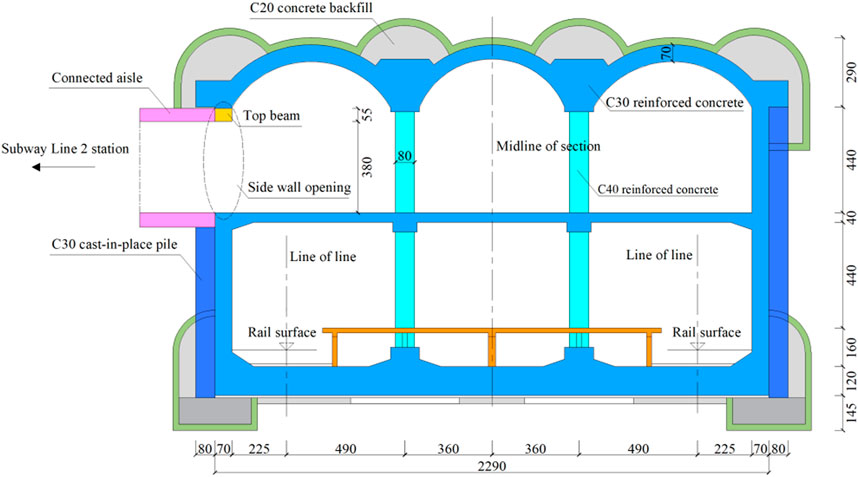
FIGURE 1. Elevation of side wall opening in Xuanwumen Station (cm).
The side wall opening can be demolished by a water drill and wire saw (Figure 2), with local parts demolished manually. During demolition, the reinforcement steel bars of existing structures at the side column and the top beam should be retained as much as possible. The interface between the new and old concrete should be chiseled and cleaned. In the construction process of the side wall opening (Figure 3), firstly, both sides ① are demolished, and concealed columns on both sides are poured. Secondly, areas ② and ③ are demolished, and temporary supports are applied. Thirdly, after structure stabilization, the temporary supports are removed, and the top beam is poured. Finally, area ④ is demolished into blocks.
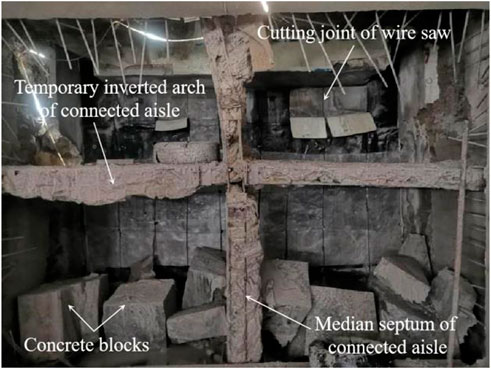
FIGURE 2. The construction site of opening demolition.
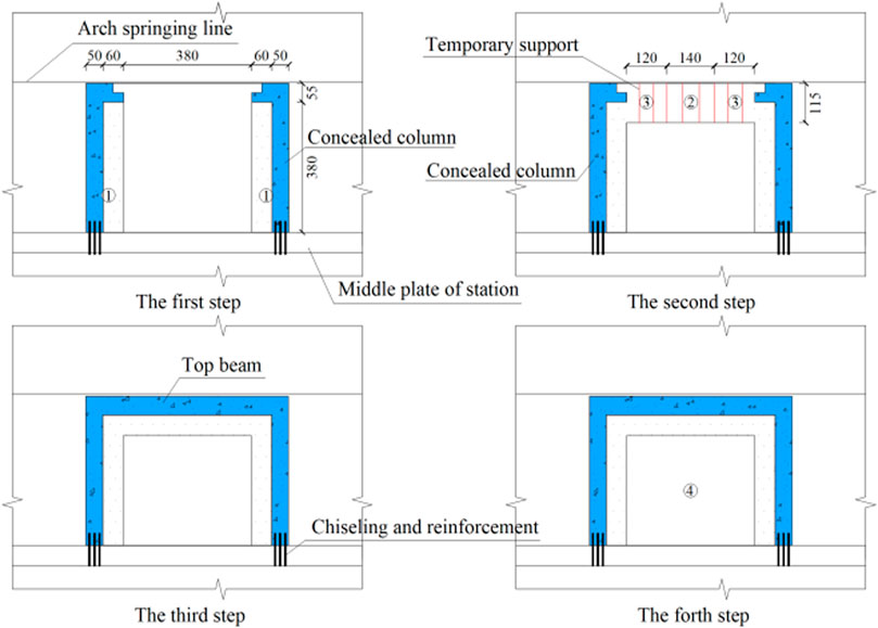
FIGURE 3. The processes of opening construction (cm).
The finite element software MIDAS GTS (version 2018R1; MIDAS Information Technology Co., Ltd., Beijing, China) is used to build a three-dimensional numerical model (Figure 4). The strata are simulated using the Mohr-Coulomb model, and the station structure is simulated using the Drucker-Prager model, both with three-dimensional solid units. The concealed column and the top beam are simulated using the Drucker-Prager model, both with three-dimensional solid units. According to a previous geotechnical investigation report (Li, 2020), the mechanical parameters of the strata and station structure are obtained (Table 1).
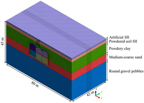
FIGURE 4. Diagram of the numerical calculation model.
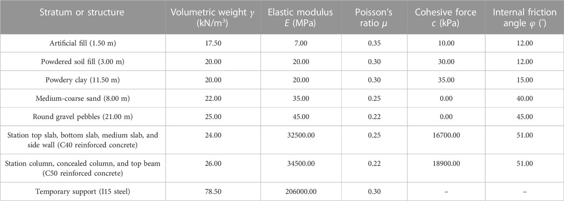
TABLE 1. Mechanical parameters of the strata and station structure.
The numerical model only considers the gravity field and does not consider the tectonic stress field. The top surface of the model is a free surface, and its front, rear, left, right, and bottom surfaces are all constrained to the displacement. Horizontal displacement constraints are imposed on the strata at the opening. The construction process of the model is shown in Figure 3. In the numerical simulation, passivating of wall elements in the existing structure, and activating of beam and column elements are used to simulate the opening construction.
Based on the model chamber size and the relevant parameters of the test instrument, the geometric similarity ratio (CL = 40) and the bulk density similarity ratio (Cγ = 1) are determined for the model tests (Liu et al., 2022). Using two these basic similarity ratios, the similarities of other parameters are derived through the similarity relations (Table 2).
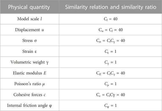
TABLE 2. Model similarity relation and similarity ratio.
The test stratum sample is proportioned with quartz sand and fine sand in a ratio of 1:3 (w/w). The mechanical parameters of the test stratum sample are determined by direct shear tests and converted to the corresponding mechanical parameters of the actual stratum through the similarity relations. The mechanical parameters of the test stratum sample are found to be close to those of the actual stratum (Table 3), which can meet the model test requirements (Xu et al., 2020; Qin et al., 2022; Zhang et al., 2022).
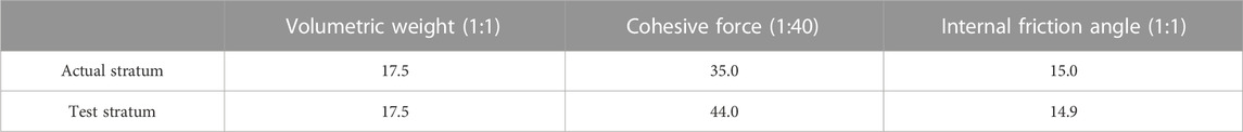
TABLE 3. Mechanical parameters of the test stratum sample.
The station model section (75 cm × 57 cm × 37 cm) is made of organic glass (a polymer of methyl methacrylate). Its modulus of elasticity is 0.69 GPa (determined by uniaxial tensile test) and Poisson‘s ratio is 0.32. The width and height of the top, middle and bottom slabs and the side wall are designed using the geometric similarity ratio CL. Its thickness is designed using the equivalent flexural stiffness [Eq. 1]:
where Em and Im are the modulus of elasticity and cross-sectional moment of inertia of the prototype material, respectively; EP and IP are the modulus of elasticity and cross-sectional moment of inertia of the test material, respectively; and CE and CL are the similarity ratios of the modulus of elasticity and geometry, respectively. The thicknesses of the top, middle, bottom slabs and the side wall of the station are calculated to be 54.3, 23.4, 121.5, and 54.3 mm, respectively, with a column diameter of 8.1 mm.
1) Uniaxial tensile test of organic glass specimens
Uniaxial tensile tests are carried out on organic glass specimens to verify whether the strength of organic glass after joining by hot melt adhesive (ethylene-vinyl acetate copolymer) is similar to that before it is cut. The specimens are designed according to the specification of the ASTM Committee on Standards (2003), with five specimens manufactured for each group. Specimens of group 1 is an organic glass whole specimen, and Specimens of group 2 is an organic glass specimen connected by hot melt adhesive. The width of hot melt adhesive in the specimens of group 2 is 2 mm. After sufficient cooling, the specimens are subjected to uniaxial tensile test. The stress–strain relationship of between the two groups of specimens is obtained by taking the mean values.
A universal testing machine is used as the loading device, which has a loading rate of 10 mm/min. The extensometer is fixed to the specimen at both ends of the gauge length (50 mm) to measure deformation. A 2-mm-thick polyvinyl chloride slab is applied to both ends of the specimen to prevent the breaking of its clamped end before the gauge length section. The device of uniaxial tensile test is shown in Figure 5. When comparing the stress–strain relationship curves of specimens in the two groups, similar trends are found (Figure 6). In both groups, the specimens show a linear increase in stress with increasing strain in the gauge length section, with a maximum error of 4.7%. This shows that the strength of organic glass specimens after joining by hot melt adhesive is relatively similar to that of uncut specimens.
2) Model test of side wall opening
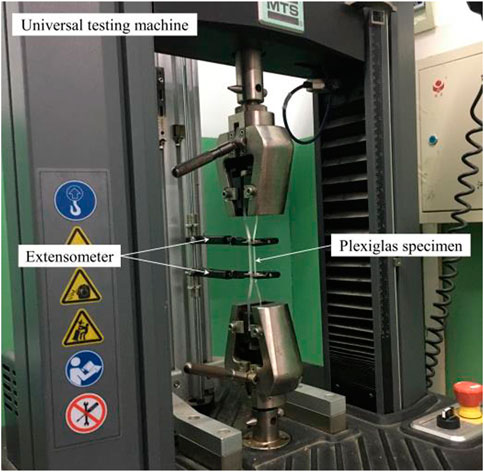
FIGURE 5. The device of uniaxial tensile test.
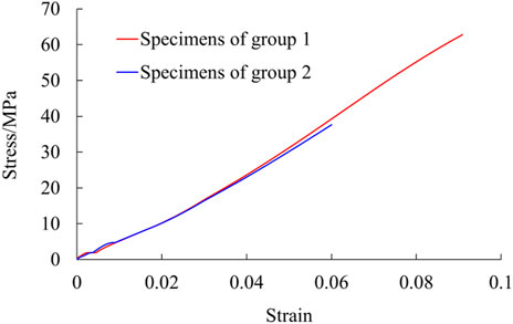
FIGURE 6. Stress–strain relationships of organic glass specimens.
The model tests are carried out in a visual model test chamber with pre-defined openings. The model chamber is made of steel and organic glass. It measures 1.5 m × 0.8 m × 1.2 m with a reserved opening of 21 cm × 17 cm. The station structure measures 75 cm × 57 mm × 37 cm and is made of organic glass, with a reserved opening in the side wall of 15 cm × 11 cm. Pre-cut organic glass blocks are used to seal the openings, leaving a 5 mm gap between the blocks. The strength of the organic glass specimen after connection by hot melt adhesive connection is relatively similar to that of the uncut specimen, and the hot melt adhesive softens quickly when exposed to heat. Therefore, the gaps between the blocks are filled with hot melt adhesive to facilitate the subsequent tests. The model test device of side wall opening is shown in Figure 7.
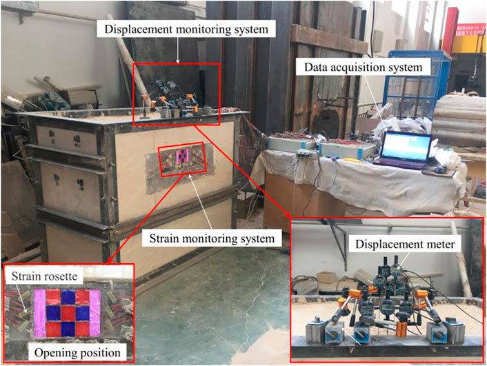
FIGURE 7. The model test device of side wall opening.
The model tests are conducted to measure the vertical displacement at the top of the side wall opening and the variation in the principal stresses around the opening. Specifically, strain rosettes are placed around the opening. When the model chamber is filled with the stratum sample to the design position, the station model is placed into the chamber, with its side wall opening aligned to the model chamber opening. Settlement bars are placed at the top slab above the side wall opening and connected to a displacement meter. Subsequently, the model chamber is filled with the remaining stratum sample. The locations of the measurement points for displacement and strain are shown in Figure 8.
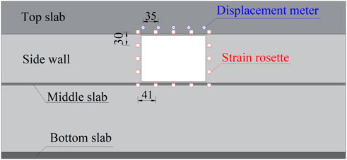
FIGURE 8. Layout of displacement and strain measurement points (mm).
The test procedure involves cutting the hot melt adhesive between organic glass blocks in the side wall opening using an electric heating cutter (Figure 9). The cutter has a 3-mm-thick blade and can reach a temperature of 500°C. The hot melt adhesive is melted at a high temperature and then slowly cut. The overall cutting speed is maintained at 1 mm/s to minimize disturbance to the existing structure. After cutting, the unloaded glass is removed and let stand for a while. Subsequent cutting operations can be carried out when the readings in the data acquisition system are less variable. In this way, the procedure of block demolition in the opening construction of the actual project is realized.
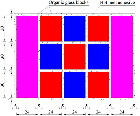
FIGURE 9. Relative position relation between organic glass blocks and hot melt adhesive (mm).
The model test results are converted into actual displacement and principal stress values through the similarity relations. The test results are then compared with the displacement and stress patterns with construction steps in numerical simulations.
1) Deformation characteristics of the existing structures in opening construction
The stress state after the completion of station construction by the pile-beam-arch method is used as the initial stress state for side wall opening construction. Figure 10 shows the vertical and horizontal deformations of the existing station structure. Subsidence occurs at the top of the opening, with the largest value at the mid-span of the top beam (1.58 mm). The subsidence gradually expands to the upper side of the vault, while its influence is diminished. There is a certain uplift at the bottom of the opening (0.97 mm), and the impact extends to the negative second floor.
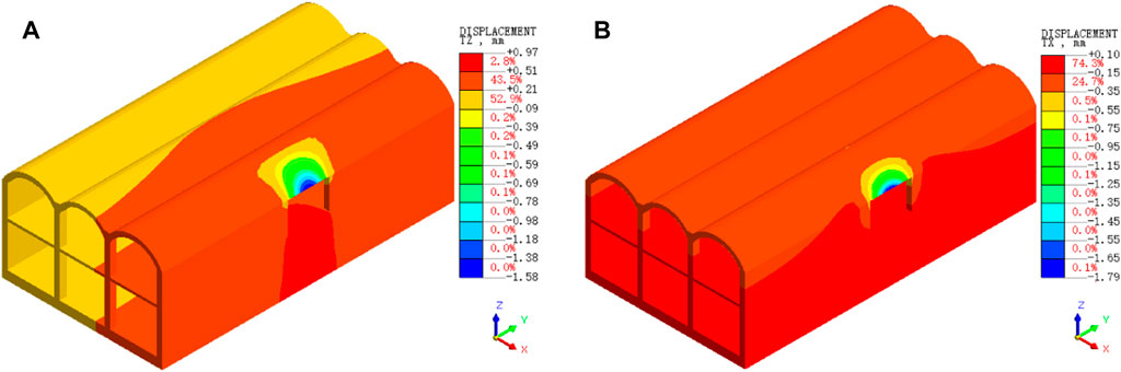
FIGURE 10. Vertical and horizontal deformations of existing station structure (mm): (A) Vertical deformation and (B) Horizontal deformation.
After the side wall opening is demolished, the station shows an inward transverse deformation at the top of the top beam (−1.79 mm), along with an outward transverse deformation at the side wall (0.10 mm). According to the relevant regulations and evaluation opinions of Beijing Subway Operation Co., Ltd. On train safety operation, when the side wall structure is demolished, the vertical and transverse allowable deformations of the existing main structure and track are 3 mm (Yuan, 2019). Therefore, the deformations of the station caused by side wall opening demolition are relatively small, and the deformations of the station and the track are in a safe state.
During opening construction, the subsidence at the top of the opening is characterized by three stages (Figure 11). In the first stage, when the two sides are demolished and the concealed columns are poured, the deformation increment is minimal (−0.17 mm). In the second stage, when the top areas are demolished and the top beam is poured, the deformation increment reaches the highest level (−1.26 mm). In the third stage, when the remaining rectangular areas are demolished, the deformation value is unchanged (−0.15 mm).
2) Stress characteristics of the existing structures in opening construction
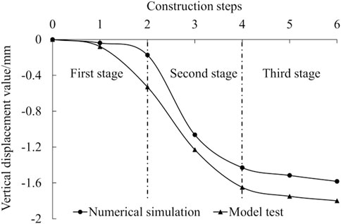
FIGURE 11. The maximum vertical displacement of existing side wall structure during opening construction.
The stress distribution of the side wall after demolition is shown in Figure 12. The first principal stress is largest at the mid-span of the top beam (1.82 MPa), and the stress increment caused by opening construction is 2.14 MPa, which indicates that the side wall below the opening should be strengthened. The third principal stress (−6.19 MPa) is concentrated at the top corner of the opening, and the stress increment caused by opening construction is −4.62 MPa. Despite the large value, it is still in the safe range. However, according to the regulations and evaluation opinions of the Beijing Subway Operation Co., Ltd., the stress change of the existing main structure should be less than 10% when demolishing the side wall structure (Yuan, 2019). Collectively, the results indicate that the stress increment caused by opening demolition has exceeded the allowable range, and can cause cracking of the concrete structure. Before demolition, the surrounding area of the opening should be strengthened, or the structural stiffness of the concealed columns and the top beams should be improved.
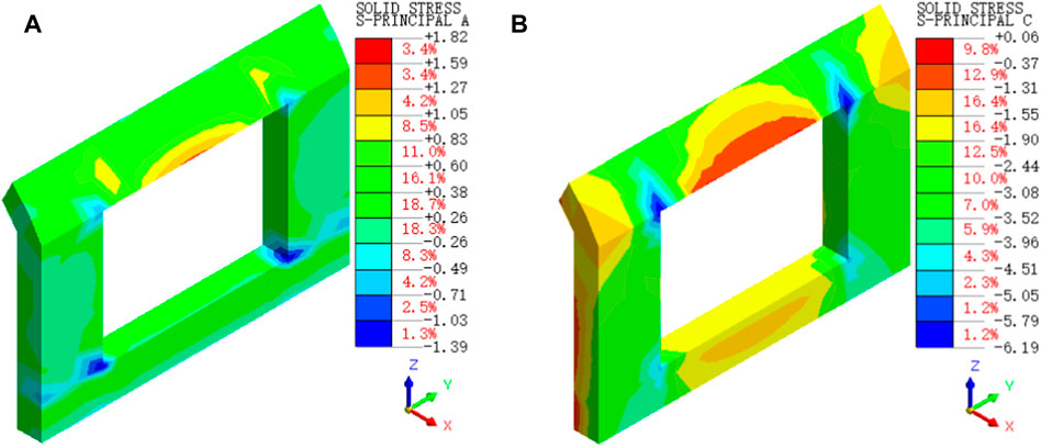
FIGURE 12. Principal stress distribution around the side wall opening (MPa): (A) First principal stress and (B) Third principal stress.
The model test results are consistent with the stress patterns based on the numerical simulations, and the principal stress around the side wall openings is characterized by three stages (Figure 13). In the first stage, when the two sides are demolished and the concealed columns are poured, the stress increment is relatively small (0.43 and −1.60 MPa). In the second stage, when the rectangular areas are demolished and the top beams are poured, the stress increment is highest (1.51 and −2.85 MPa). In the third stage, when the remaining rectangular areas are demolished, the stress value is unchanged (0.02 and −0.06 MPa).
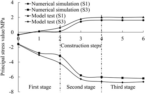
FIGURE 13. Variation in the principal stresses of existing side wall structure during opening construction.
After the opening construction, the envelope curves of the principal stresses are shown in Figure 14. Although the model test results are slightly higher than the numerical simulation results, the distribution patterns of the principal stresses are consistent.
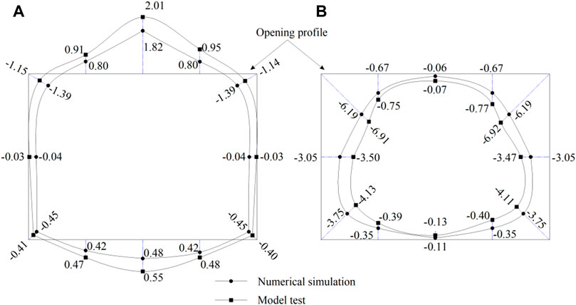
FIGURE 14. Envelope diagrams of the principal stresses around the side wall opening (MPa): (A) First principal stress and (B) Third principal stress.
Comparing the numerical simulation and model test results reveal consistent variation in the distribution patterns of displacement and stress around the side wall opening. The first principal stress is concentrated at the mid-span of the top and the bottom, with higher values at the top (1.82 MPa) than at the bottom (0.48 MPa). The third principal stress is concentrated at the corners of the top and bottom, with higher values at the top (−6.19 MPa) than at the bottom (−3.75 MPa). The top mid-span and corners of the opening are force-sensitive positions during construction.
The above-mentioned opening construction problem can be approximated as an excavation problem for the strata. Strata excavation can be considered as the first “opening construction”. The vertical and horizontal stresses around the station structure are used to calculate the load, i.e., the surrounding rock pressure exerted on the station structure. Side wall excavation can be considered as the second “opening construction”. The total vertical stress and the total horizontal stress are used to calculate the state of stress distribution around the opening. The theoretical analysis process is illustrated in Figure 15.
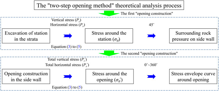
FIGURE 15. Theoretical analysis process of the “two-step opening” method.
1) The station excavated in the strata is a rectangular structure.
2) The side wall of the station structure is considered infinite body.
3) The materials of strata and station structure are continuous, uniform, and isotropic.
The excavated station structure is subjected to vertical and horizontal stresses exerted by the strata (Figure 16). The vertical stress (Pz = −156.25 kPa) is obtained by Eq. 2, and the horizontal stress (Px = −67.19 kPa) is obtained by Eq. 3.
where γi is the volumetric weight of each stratum above the top slab of the station structure, hi is the corresponding stratum thickness, μi is the corresponding Poisson’s ratio, and n is 3. The relevant parameters are given in Table 1.
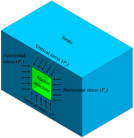
FIGURE 16. Stress distribution in the first “opening construction”.
Based on a complex function solution to the orifice problem (Sa, 1958), the stress equations for the rectangular orifice perimeter is shown in Eq. 4, Eq. 5, Eq. 6.
where θ is the angle around the opening relative to the midline of the section (θ = 0°–360°);
The stress on the station structure is obtained by taking the corresponding values θ). The stress at a 45° angle to the midline of the section (θ = 45°) is chosen as the surrounding rock pressure on the side wall of the station structure (σ45˚ = −652.53 kPa; Figure 17).
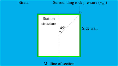
FIGURE 17. Schematic diagram of surrounding rock pressure on the side wall.
The side wall opening in the station structure is subjected to the surrounding rock pressure exerted by the strata and the self-weight stress of the side wall (Figure 18). The surrounding rock pressure has been calculated for the first-step opening (σ45˚ = −652.53 kPa). The self-weight stress (σcz = −360 kPa) is obtained by Eq. 2, where γ = 24 kN/m3, h = 15 m, and n = 1. The sum of the surrounding rock pressure and the self-weight stress (σ45˚+σcz = −1052.53 kPa) is taken as the total vertical stress (Pz՛) of the second “opening construction”. The total horizontal stress (Px՛) is obtained by Eq. 3, where μ = 0.25 and n = 1.
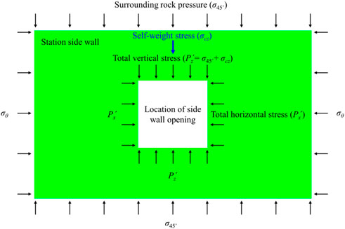
FIGURE 18. Stress distribution in the second “opening construction”.
The stress around the opening (σθ՛) is obtained by Eq. 4, Eq. 5, Eq. 6. Then, the stress distribution around the opening obtained by the theoretical analysis is compared with that obtained by the numerical simulation (Figure 19). Both methods reveal similar stress distribution patterns, but the stress values obtained from the theoretical analysis are lower. This is mainly because the equations used for the theoretical analysis are applicable to the “opening construction” in the strata, whereas the second “opening construction” is carried out in the station structure. In addition, it is possible that the first “opening construction” has resulted in a rectangular structure, whereas the actual structure is vaulted.
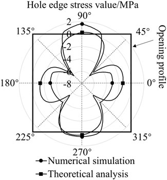
FIGURE 19. Stress distribution around the side wall opening.
The concealed columns and top beams contribute to the reinforcement of the existing structure around the side wall opening. However, it is easy to find that, at a certain span, the displacement and stress are within the safe range, even without reinforcement. The construction period and cost can be considerably reduced if the concealed columns and top beams are not poured. A comparative analysis of five opening spans (4.35, 5.00, 5.50, 6.00, and 8.00 m) is carried out with the opening height being kept constant (4.35 m). Using the allowable vertical deformation (−3 mm) and the design tensile strength of C40 concrete (1.71 MPa), the maximum opening spans that the structure can withstand without strengthening measures are 7.45 and 5.75 m, respectively (Figure 20). The minimum value of 5.75 m is taken as the ultimate opening span.
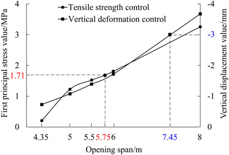
FIGURE 20. Ultimate opening span under allowable conditions.
When the opening span is greater than 5.75 m, two construction control measures are proposed: temporary steel supports alone and combined with a plugging wall (Table 4). With the opening height being kept constant (4.35 m), four opening spans (5, 6, 8, and 10 m) are adopted to analyze the corresponding ultimate opening spans under different reinforcement measures.
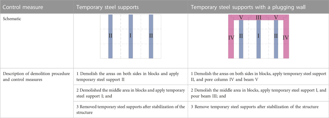
TABLE 4. Description of opening construction control measures.
The first principal stress as a major influencing factor is taken as the control condition. The ultimate opening span under reinforcement with temporary steel supports is 6.94 m, and that under reinforcement with a combination of temporary steel supports and a plugging wall is 9.28 m (Figure 21).
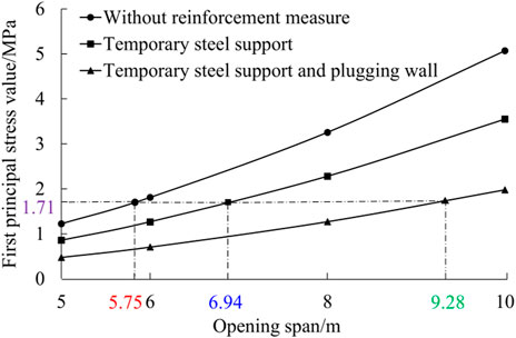
FIGURE 21. Ultimate opening span under different reinforcement measures.
In this study, the mechanical properties of existing subway station structure are derived from the construction of side wall opening. The following conclusions are reached based on numerical simulations, model tests, and theoretical analysis.
1) During the opening construction, the variation in displacements and stresses is characterized by three stages: slow growth, rapid growth, and almost stable. Tensile stresses are concentrated at the mid-span and compressive stresses are concentrated at the corners. In practical engineering, attentions should be paid to the rapid growth stage and the stress concentration in the top mid-span and the corners of opening.
2) There is rapid growth of displacements and stresses when the uppermost layer of the structure is demolished. The opening should be strengthened at this location and even at the top beam before construction.
3) During the opening construction, the displacement of the existing structure is less than 3 mm and under the safe criteria, but the stress increment of the structure exceeds the control criteria, indicating that the stress variation should receive attention during construction.
4) According to the variation characteristics of displacement and stress during the opening construction, it is seen that the sensitive areas of the structure are the top mid-span (maximum vertical displacement and first principal stress) and the corners (maximum third principal stress).
5) The “two-step opening” method can be used for opening analysis of side walls in underground space structures according to the study of this paper.
6) An increase in the opening span can result in a sharp increase in the tensile stresses at the mid-span. The ultimate opening span without reinforcement measures is 5.75 m; temporary steel support reinforcement measures are suggested to be conducted, when the opening span is between 5.75 m–6.94 m; reinforcement measures containing temporary steel supports and plugging walls are suggested to be implemented, when the opening span is between 6.94 m–9.28 m.
The original contributions presented in the study are included in the article/supplementary material, further inquiries can be directed to the corresponding authors.
ZH and HM wrote the manuscript. ZL revised the manuscript. LZ conceived the experiments, and contributed to the data interpretation. All authors have read and agreed to the published version of the manuscript.
The Young Talent Program of the Hebei Provincial Education Department (BJ2019009), the National Natural Science Foundation of China (52178392), the Central Leading Local Science and Technology Development Fund Program (226Z5403G), and the Excellent Youth Program of the Hebei Provincial Natural Science Foundation (E2021210025), China.
Author LZ was employed by the company Shijiazhuang State-owned Capital Investment and Operation Group Co., Ltd, China.
The remaining authors declare that the research was conducted in the absence of any commercial or financial relationships that could be construed as a potential conflict of interest.
All claims expressed in this article are solely those of the authors and do not necessarily represent those of their affiliated organizations, or those of the publisher, the editors and the reviewers. Any product that may be evaluated in this article, or claim that may be made by its manufacturer, is not guaranteed or endorsed by the publisher.
Abdellah, W. R. (2017). Serviceability analysis of deep underground openings driven in jointed-rock. Int. J. Min. Sci. Technol. 27 (6), 1019–1024. doi:10.1016/j.ijmst.2017.06.024
Ahmed, I. E., Hassan, M. H., and Mohammed, A. E. S. A. (2020). Effect of longitudinal opening on the structural behavior of reinforced high-strength self-compacted concrete deep beams. Case Stud. Constr. Mat. 12, e00348. doi:10.1016/j.cscm.2020.e00348
ASTM Committee on Standards (2003). ASTM standard D638 standard test method for tensile properties of plastics. West Conshohocken, PA, USA: ASTM International. doi:10.1520/D0638-10.1
Aydan, O. (2019). Dynamic response of support systems during excavation of underground openings. J. Rock Mech. Geotech. Eng. 11, 954–964. doi:10.1016/j.jrmge.2019.06.002
Jia, P., Zhu, W. C., and Zhang, S. C. (2014). Effect of heterogeneity on occurrence of zonal disintegration around deep underground openings. Int. J. Min. Sci. Technol. 24 (6), 859–864. doi:10.1016/j.ijmst.2014.10.020
Kong, C., Wang, H. Y., Zhao, K., and Gao, X. Q. (2022). Numerical simulation of long-term deterioration of rock mass supported by shotcrete lining. Front. Earth Sci. 10, 891084. doi:10.3389/feart.2022.891084
Li, A., Liu, Y., Dai, F., Liu, K., and Wei, M. D. (2020). Continuum analysis of the structurally controlled displacements for large-scale underground caverns in bedded rock masses. Tunn. Undergr. Sp. Technol. 97, 103288. doi:10.1016/j.tust.2020.103288
Li, R. Z. (2020). Three-dimensional seismic response analysis of arched subway station structure with side wall opening. Def. Transp. Eng. Technol. 18 (2), 26–29. (in Chinese). doi:10.13219/j.gjgyat.2020.02.007
Liu, N. F., Li, N., Li, G. F., Song, Z. P., and Wang, S. J. (2022). Method for evaluating the equivalent thermal conductivity of a freezing rock mass containing systematic fractures. Rock Mech. Rock Eng. 55 (12), 7333–7355. doi:10.1007/s00603-022-03038-9
Liu, S. H., Liu, J. W., and Zhang, D. X. (2018). Field measurement and analysis of the influence of break construction on the structure of existing subway stations. Munic. Technol. 36 (5), 105–108 [in Chinese].
Moon, W. C., Lau, T. L., and Puay, H. T. (2020). Experimental investigations of tsunami loading on internal wall of a building with various openings and wall configurations. Coast. Eng. 158, 103691. doi:10.1016/j.coastaleng.2020.103691
Nassernia, S., and Showkati, H. (2017). Experimental study of opening effects on mid-span steel plate shear walls. J. Constr. Steel Res. 137, 8–18. doi:10.1016/j.jcsr.2017.05.021
Qin, Y. W., Lai, J. X., Gao, G. Q., Yang, T., Zan, W. B., Feng, Z. H., et al. (2022). Failure analysis and countermeasures of a tunnel constructed in loose granular stratum by shallow tunnelling method. Eng. Fail. Anal. 141, 106667. doi:10.1016/j.engfailanal.2022.106667
Saad-Eldeen, S., Garbatov, Y., and Soares, C. G. (2018). Structural capacity of plates and stiffened panels of different materials with opening. Ocean. Eng. 1671, 45–54. doi:10.1016/j.oceaneng.2018.08.013
Sun, L. Z., Chen, H., Luan, W. W., Xing, W., and Zhao, W. (2014). Study of structure linking technology between new and old subway stations. J. Undergr. Sp. Eng. 10 (S1), 1673–1678 [in Chinese].
Wallace, M. I., and Ng, K. C. (2016). Development and application of underground space use in Hong Kong. Tunn. Undergr. Sp. Technol. 55, 257–279. doi:10.1016/j.tust.2015.11.024
Wu, S. P., and Yan, A. (2017). Construction technology for connecting subway entrances and new projects. Constr. Technol. 46 (12), 53–56. (in Chinese). doi:10.7672/sgjs2017120053
Xu, P., Wu, Y. M., Wang, Z. J., and Huang, L. (2020). Distribution laws of freeze-thaw cycles and unsaturated concrete experiments in cold-region tunnels. Cold Reg. Sci. Technol. 172, 102985. doi:10.1016/j.coldregions.2019.102985
Yin, C., Li, H. R., Che, F., Li, Y., Hu, Z. N., and Liu, D. (2020). Susceptibility mapping and zoning of highway landslide disasters in China. Plos One 15 (9), 0235780. doi:10.1371/journal.pone.0235780
Yin, C., and Zhang, J. L. (2018). Hazard regionalization of debris-flow disasters along highways in China. Nat. Hazards 91 (1), 129–147. doi:10.1007/s11069-018-3229-8
Yuan, C. Y. (2019). Safety analysis of side wall opening at existing subway station. Munic. Eng. Technol. 37 (2), 106–109 [in Chinese].
Zabihi, S., Mamazizi, A., and Ghanbari-Ghazijahani, T. (2021). A study on mid-panel of steel shear-walls with dual openings. J. Constr. Steel Res. 186, 106869. doi:10.1016/j.jcsr.2021.106869
Zaher, O. F., Yossef, N. M., El-Boghdadi, M. H., and Dabaon, M. A. (2018). Structural behaviour of arched steel beams with cellular openings. J. Constr. Steel Res. 148, 756–767. doi:10.1016/j.jcsr.2018.06.029
Zhai, X. M., Zhang, X. S., Cao, C., and Hu, W. B. (2019). Study on seismic performance of precast fabricated RC shear wall with opening filling. Constr. Build. Mat. 214, 539–556. doi:10.1016/j.conbuildmat.2019.04.070
Zhang, Y. W., Fan, S. Y., Yang, D. H., and Zhou, F. (2022). Investigation about variation law of frost heave force of seasonal cold region tunnels: A case study. Front. Earth Sci. 9, 806843. doi:10.3389/feart.2021.806843
Zhang, Y. W., Song, Z. P., Weng, X. L., and Xie, Y. L. (2019). A new soil-water characteristic curve model for unsaturated loess based on wetting-induced pore deformation. Geofluids 2019, 1–14. doi:10.1155/2019/1672418
Keywords: side wall opening, structure demolition, mechanical behaviors, theoretical analysis, ultimate opening span
Citation: Hu Z, Mao H, Zhang L and Liu Z (2023) Experimental tests and theoretical analysis for mechanical behaviors of side wall opening construction in mined excavation subway station. Front. Earth Sci. 11:1127078. doi: 10.3389/feart.2023.1127078
Received: 19 December 2022; Accepted: 17 January 2023;
Published: 01 February 2023.
Edited by:
Yuwei Zhang, Xi’an University of Architecture and Technology, ChinaReviewed by:
Peng Xu, Ningxia University, ChinaCopyright © 2023 Hu, Mao, Zhang and Liu. This is an open-access article distributed under the terms of the Creative Commons Attribution License (CC BY). The use, distribution or reproduction in other forums is permitted, provided the original author(s) and the copyright owner(s) are credited and that the original publication in this journal is cited, in accordance with accepted academic practice. No use, distribution or reproduction is permitted which does not comply with these terms.
*Correspondence: Lixin Zhang, emhhbmdsaXhpbjYxNkBzaW5hLmNvbQ==; Zhichun Liu, bGl1emhjaDAxQDE2My5jb20=
Disclaimer: All claims expressed in this article are solely those of the authors and do not necessarily represent those of their affiliated organizations, or those of the publisher, the editors and the reviewers. Any product that may be evaluated in this article or claim that may be made by its manufacturer is not guaranteed or endorsed by the publisher.
Research integrity at Frontiers
Learn more about the work of our research integrity team to safeguard the quality of each article we publish.