 Xiang He1,2,3
 Ke Yang
- 1Joint National-Local Engineering Research Centre for Safe and Precise Coal Mining, Anhui University of Science and Technology, Huainan, Anhui, China
- 2Hefei Comprehensive National Science Center, Institute of Energy, Hefei, Anhui, China
- 3School of Mining Engineering, Anhui University of Science and Technology, Huainan, Anhui, China
- 4Emergency Science Research Institute, Chinese Institute of Coal Science, Beijing, China
- 5School of Energy and Mining Engineering, China University of Mining and Technology (Beijing), Beijing, China
The methods of numerical simulation and on-site measurement is used to analysis reasonable coal pillar width (CPW) and roadway support in isolated panel of extra-thick coal seam. Numerical modeling shows that a maximum vertical stress in isolated panel is 32.9 MPa, and stress concentration factor reaches 2.99, which is more affected by the mining of adjacent panel, and the peak stress on both sides is higher. By comparing the failure and deformation characteristics of different pillar widths, it is shown that a 6 m pillar can reach the load requirements of overlying strata and ensure that the roadway is in an undamaged and controllable environment. According to the asymmetry of surrounding rock deformation, the final joint control technology of asymmetric anchor cables, high intensity anchor cables, and coal pillar grouting is proposed and get good control effect on site. The research results provide guidance value for surrounding rock control under similar geological condition.
1 Introduction
As the development of modern productive and effective coal mines, extra-thick coal seams have increasingly been the major coal seams in China (Si et al., 2015; Tewari et al., 2018). Recoverable reserves of thick and extra-thick coal seam in China account for approximately 43% of a overall recoverable reserve of coal in China (Poulsen, 2010; Bai et al., 2015). Thick and extra-thick seams have a variety of mining methods due to their large coal seam thickness. At present, the fully mechanized caving mining method is widely promoted and practiced in China, such as Datong mining area, Pingshuo mining area, Shendong mining area, etc (Kang et al., 2009; Shen, 2013; Lisjak and Grasselli, 2014; Gao and Kang, 2016). The fully mechanized caving mining method will produce a certain proportion of coal loss (He et al., 20202020). Reasonable pillar reservation plays a key role in maintaining the stability and safety of the stope and reducing coal waste (Medhurst and Brown, 1998).
Currently, a number of mining experts have performed extensive investigation on the stability and size of yield pillar. According to the integrated pressure and deformation measurement device, Yu et al. (Yu et al., 2016) studied the pressure and displacement variation characteristics of yield pillars. By considering joint fissures, Esterhuizen et al. (Esterhuizen et al., 2011) proposed a mathematical formula to calculate coal pillar strength. According to method of numerical simulation and field application, Jawed and Sinha (Jawed and Sinha, 2018) studied the coal pillar design and roadway stability under the condition of inclined thin seam. By selecting a reasonable constitutive model for coal pillar, Zhang et al. (Zhang et al., 2017) analyzed the variation of stress and extent of damage. According to field data collected on a coal pillar in underground area, Salamon et al. (Salamon and Munro, 1967; Salamon, 1970; Salamon et al., 1998) developed an equation that considers the pillars strength and size, which is successfully adopted for pillar design. Through writing FISH language and drilling peeps, Wu et al. (Wu et al., 2018) explored distribution characteristics of tension fractures and shear fractures at coal pillars of different sizes, laying a foundation for the study of surrounding rock control. Based on the discrete element numerical simulation method, Gao et al. (Gao et al., 2015) reveals the mechanism of extrusion deformation occurring in coal pillars, which provides guidance basis for gob-side entry support. Through numerical simulation and laboratory experiments, Li et al. (Li et al., 2014) investigated the plastic zone distribution characteristic of yield pillar rib and solid coal rib to guide a pillar design. Wang et al. (Wang et al., 2016) explored the deformation velocity and acceleration of different coal pillar sizes with the effect of dynamic loads. By analyzing overall process of coal pillar deformation and failure, Wagner obtained that the existence of elastic zone is conducive to maintaining the stability of yield pillar. By exploring the evolution characteristics of deviatoric stress in deep large deformation surrounding rock, Wang et al. (Wang and Xie, 2022) proposed to use anchor cable truss for horizontal and vertical displacement control. Yang et al. (Yang et al., 2017) used shotcrete and bolt to control the roadway failure through simulating the law of crack propagation in the roadway under supported and unsupported conditions.
Above research performed a lot of investigation on the stability and size design of coal pillar to ensure the safe production of the panel. However, there are few studies on coal pillar in the isolated panel with the extra-thick coal seam. In view of this, the means of numerical model and on-site test were adopted to explore the evolution law of yield pillar failure and deformation in the isolated panel with extra-thick coal seams, and then clarify the CPW and roadway support scheme.
2 Project overview
The N8102 panel mainly mines coal 3–5#, with the thickness of 18 m and a average dip angle of 1°. The alignment and inclined length is 1,516 m and 251 m, respectively. The buried depth of the panel is 450 m. Surrounding areas of N8102 panel are solid coal area, N8101 gob, three panel main roadways and N8103 gob, as shown in Figure 1.
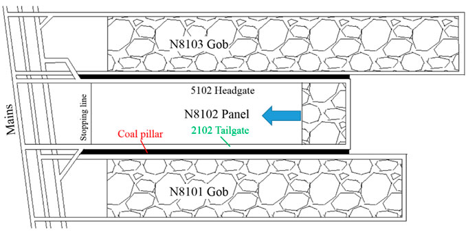
FIGURE 1. The relative position of N8102 panel.
The roof of 2,102 tailgate is as follows: A main roof is 10 m thick medium coarse-grained sandstone. A immediate roof is 5 m thick carbonaceous and sandy mudstone. A immediate floor is 2 m thick high-collared mudstone and sandy mudstone. A main floor is 6 m thick sandy mudstone. Figure 2 shows a comprehensive geological histogram of N8102 panel.
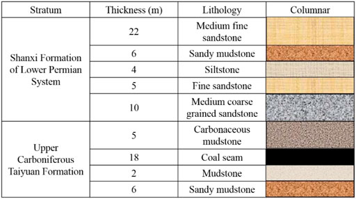
FIGURE 2. The comprehensive geological histogram of the N8102 panel.
3 Numerical simulation
3.1 Numerical modeling
Taking practical engineering geological environment of 8,102 panel as the background, the panel and the panel on both adjacent sides are selected to establish a model (Figure 3). Specific dimension of the model is 750 m × 300 m × 90 m.
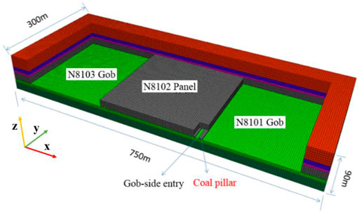
FIGURE 3. Numerical model.
Due to the non-homogeneity of a rock mass within a strata, the physico-mechanical parameters obtained in a laboratory are those of intact rock. The mechanical parameters in the laboratory are modified to apply to the actual conditions of a rock mass. Therefore, a rectangular model with dimensions of 12 m × 12 m × 24 m (length × width × height) is created to simulate the compression process of a rock mass, where the mesh size is consistent with the dimensions of the roadway surrounding rock in this paper. By using a trial-and-error approach, parameter modification is considered complete when the macro-mechanical characteristics in a model are consistent with the field. As the mined space on both sides of N8102 isolated panel is huge, double yielding model is used to simulate the filling effect of the gangue, which can reflect the support action of the gangue caving from the goaf. The model adopts the Moore-Coulomb damage criterion with fixed displacements around all sides and bottom of a model, with vertical loads applied to its top. Buried depth of N8102 panel is 450 m. Bulk density of overlying strata is 2,500 kg/m3. The load applied on the model is 9.922 MPa. Table 1 shows the parameters of each rock stratum when the numerical model is established. Elastic modulus, Poisson’s ratio, cohesion and tensile strength are modified in a certain proportion according to the laboratory test results (Itasca, 2007; Cai et al., 2013).
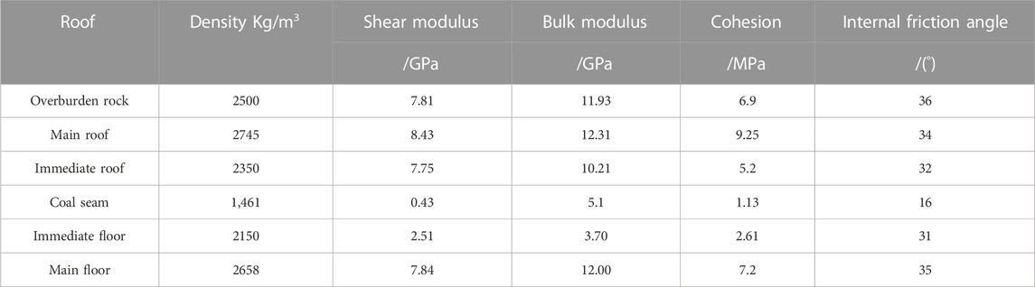
TABLE 1. Parameter selection of coal and rock.
3.2 Stress distribution characteristics of isolated panel
During the simulation of excavation, Tecplot software was used to extract the distribution data and stress nephogram of the vertical stress in N8102 panel after mining on one side and mining on both sides, as shown in Figure 4. Statistical charts were drawn by Origin platform (Figure 5).
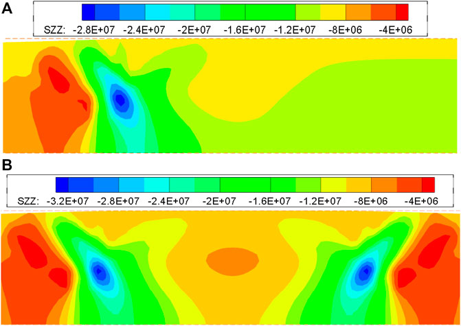
FIGURE 4. Variation characteristics of vertical stress in N8102 panel after mining. (A) Mining on one side; (B) mining on both sides.
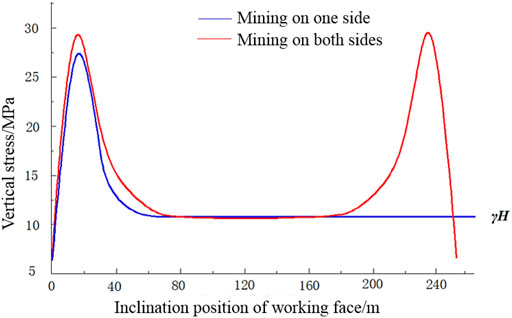
FIGURE 5. Vertical stress distribution curve.
The comparative analysis of Figures 4, 5 shows that.
1) After the mining of N8101 panel is completed and the gob collapse is stable, a bearing pressure concentration area is formed at the side of N8102 panel close to the goaf. Peak stress at the roadway middle line can reach 28 MPa, and the stress concentration factor is 2.55. This is because as N8101 panel is mined, the roof is broken, and the bearing stress is transferred to the panel. Vertical stress of the panel reaches more than 25 MPa within the range of 9–20 m, and the peak stress occurs at 14.5 m from the side wall of the gob. As far as 55 m distance to the coal barrier, the vertical stress in N8102 panel should drop to the in-situ stress. Because N8101 panel has a large mining space, the effect extent of lateral abutment stress is large.
2) After the mining of N8101 and N8103 panels is completed, and the overlying strata collapse stably, the vertical stress concentration area appears on both sides of N8102 isolated panel. Because the mining space on both sides is roughly equal, and the coal seam thickness and roof lithology are similar, the vertical stress of the isolated panel is symmetrically distributed. Maximum vertical stress is 32.9 MPa, and a stress concentration factor reaches 3.0. Within the change from 0 to 5.2 m on both sides of the panel, minimum vertical stress reaches 6.4 MPa, and then stress increases rapidly to reach the in-situ stress at 5.2 m. This is because the shallow solid coal side is greatly affected by mining and is severely damaged. The internal bearing capacity of broken coal body is lower than that of deep coal body, and stress also transfers to the deep solid coal. It indicates that the range 0–5.2 m is the broken area of the coal body. The stress continues to increase, reaching the peak stress at 14.2 m, that is, the elastoplastic junction of coal mass, and then reducing to in-situ stress at 70 m, which is called the stress rise zone.
3) It can be seen from the comparison between mining on one side and mining on both sides of N8102 panel that isolated panel is more impacted by the adjacent panels extraction, and maximum stress in the concentration area is higher. The isolated panel is also affected by the lateral abutment pressure in a larger range, and the stress environment is more complex. Therefore, in the process of gob-side entry driving at isolated panel, selecting a scientific and reasonable CPW is more important for the control surrounding rock stability.
3.3 Vertical stress analysis of different CPW during roadway excavation
When the numerical calculation software reaches convergence, vertical stress distribution of the yield pillar in N8102 isolated panel is obtained (Figure 6). Tecplot software is used to set the vertical stress measuring line in the middle of coal pillar simulation schemes. Distribution size of vertical stress in the yield pillar extracted by the monitoring line is obtained (Figure 7). Peak stress distribution curve of virgin rib and pillar rib are obtained (Figure 8).
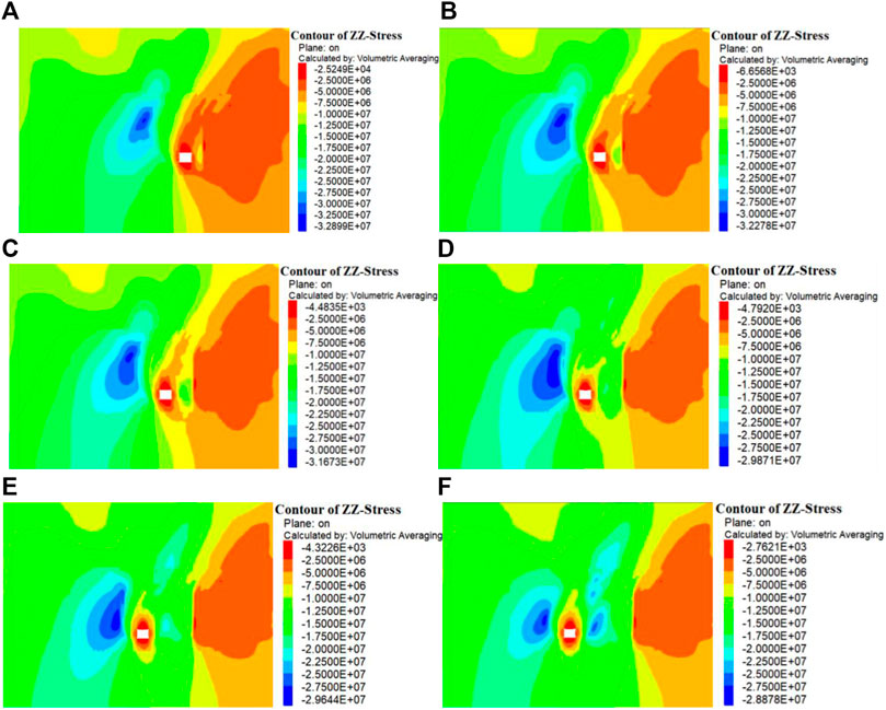
FIGURE 6. Vertical stress distribution characteristics with various CPW. (A) 4 m; (B) 6 m; (C) 8 m; (D) 12 m; (E) 16 m; (F) 22 m.
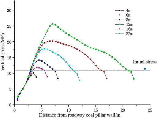
FIGURE 7. Vertical stress distribution curve with different CPW.
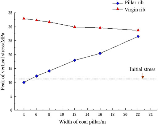
FIGURE 8. Peak of vertical stress distribution curve.
From the above analysis that a lateral abutment pressure concentration area in N8102 panel is located in the middle of the solid coal rib slightly higher than the roadway. The maximum of the stress concentration area is 32.9 MPa. With the increase of CPW, roadway approaches stress concentration area, and peak value of the lateral abutment pressure decreases from 32.9 MPa to 28.9 MPa. With the increase of CPW, surrounding rock stress becomes larger and larger. When CPW is small, the roadway is generally in a safe and stable environment at the side of the adjacent gob. When CPW is greater than 8 m, vertical stress of surrounding rock increases rapidly. When the CPW is less than 8 m, the roadway is less influenced by the high lateral abutment pressure on the solid coal side. When CPW reaches 12 m, lateral abutment stress begins to transfer to the coal pillar side, the stress concentration begins to appear within the yield pillar and peak stress is greater than in-situ stress.
As shown in Figure 7, when CPW increases from 4–22 m, vertical stress of yield pillar presents an obvious unimodal distribution, and presents a pattern of increase followed by decrease from the gob side to the roadway side. Stress concentration occurs in the yield pillar, and stress concentration factor is different, and the factor increases with the increase of CPW. When CPW increases from 4 m–8 m, stress extreme value in the yield pillar is always closer to the gob side. When CPW increases from 8 m–22 m, vertical stress extreme value in the yield pillar is closer to the side of roadway. When CPW is 4 m, maximum of the vertical stress in the narrow yield pillar is lower than the in-situ stress at the depth of coal pillar. It indicates that a large area of crushing area appears in the yield pillar and its support capacity is correspondingly reduced due to breaking rotation of rock and high lateral bearing pressure of the panel. In the process of increasing the CPW from 6 m–22 m, extreme value of vertical stress inside the yield pillar is always greater than the in-situ stress at the depth of pillar, and the area where the stress inside the yield pillar is greater than in-situ stress is closely associated with CPW. After the CPW increases, bearing capacity to the overlying rock is also enhanced.
As shown in Figure 8, when CPW increases from 4–22 m, peak stress on the yield pillars continues to increase. When CPW is 4 m, peak stress of the yield pillar is lower than the initial stress at depth of pillar. It shows that the 4 m yield pillar is greatly influenced by panel excavation, and damage enters a broken state. When CPW is 6 m, peak stress of the yield pillar begins to exceed the initial stress, indicating that the 6 m coal pillar has good bearing capacity.
3.4 Effect of CPW on vertical displacement during roadway excavation
From Figures 9, 10, the roof subsidence shows an increasing trend as the CPW increases. When the CPW is less than 8 m, the roof subsidence rises slowly. The maximum roof subsidence for the 6 and 8 m CPW is 390 mm and 410 mm respectively, an increase of 24.5% and 33.9% respectively compared to the 4 m pillar width. Meanwhile, as the CPW increases, the position of maximum roof subsidence shifts from the side of pillar towards the centre of roof. When the CPW is greater than 8m, roof subsidence in a roadway begins to rise sharply. The maximum subsidence at 12 m and 20 m CPW increases by 68.1% and 141.6% respectively compared to the 4 m pillar width. Among them, the location of maximum subsidence is distributed in the middle of a roof.
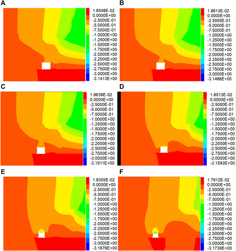
FIGURE 9. Vertical displacement distribution characteristics at various CPW. (A) 4 m, (B) 6 m, (C) 8 m, (D) 12 m, (E) 16 m, (F) 22 m.
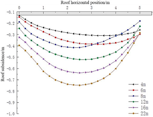
FIGURE 10. Roof subsidence with various CPW.
3.5 Effect of CPW on horizontal displacement during roadway excavation
Under the conditions of coal pillar with different widths, the displacement characteristics at pillar ribs and solid coal ribs are that the displacement above the rib is significantly greater than the displacement at the lower end of the rib (Figure 11). It can be seen that the roadway pressure mainly comes from the key block rotary subsidence at the upper part and the high lateral abutment pressure. Because the coal seam of N8102 panel is very thick, the pressure is mainly concentrated in the position inclined to the upper side of a roadway.
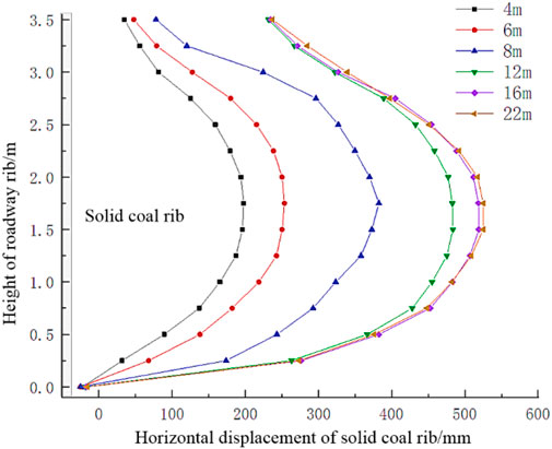
FIGURE 11. Horizontal displacement of solid coal rib at various CPW.
As the CPW grows, the solid coal rib is more seriously affected by it, and the horizontal displacement increases (Figure 12). The maximum horizontal displacements on coal pillar ribs and solid coal ribs of 6 m pillar width are 403 mm and 272 mm respectively, an increase of 56.3% and 38% respectively compared to the 4 m pillar. The reason for this is that the 4 m coal pillar is severely fractured, with prominent propagation of plastic characteristics, resulting in a reduction in its load carrying capacity. The 6 m pillar has a good bearing capacity, and the deformation increases with the rise of pressure. As the CPW continues to increase to 12 m, the load bearing capacity of a pillar is rising, resulting in a gradual reduction in the horizontal displacement of pillar rib. When the CPW is greater than 12 m, the horizontal displacement on a pillar rib shows an increasing trend due to the gradual transfer of stresses on solid coal rib into pillar rib.
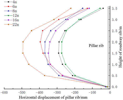
FIGURE 12. Horizontal displacement at coal pillar rib under various CPW condition.
3.6 Deformation of surrounding rock with different CPW
Figure 13 illustrates a variation curve of the deformation of a roadway and the CPW. The maximum deformation at a roadway with various CPW is obtained in Figure 13.
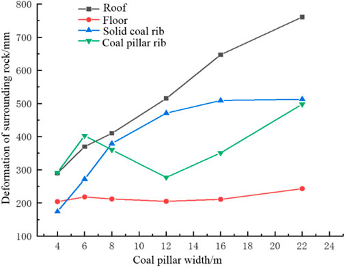
FIGURE 13. Roadway deformation with different CPW.
3.6.1 Roof subsidence
When the CPW is raised to 6 m, the amount of roof subsidence rises by 100 mm compared to a 4 m pillar, resulting in a 34% increase. As width of coal pillar rise to 8 m, the roof subsidence increases by 20 mm, an increment of only 5.1% compared to 6 coal pillars. As the CPW continues to increase to 12, 16, and 22 m, the roof subsidence increases by 32%, 66%, and 95% compared with 6 m coal pillar, respectively.
3.6.2 Floor heave
Floor heave is relatively stable on the whole. Compared with 6 m coal pillar, the floor heave of 4, 8, 12, 16, and 22 m coal pillars has increased by −6.4%, −2.7%, −6%, −3.2%, and 11.5%, respectively and the overall fluctuation is not large.
3.6.3 Displacement of coal pillar ribs
The displacement of coal pillar rib illustrates a trend of increasing, then reducing and finally gradually rising as the CPW increases. When the CPW is 6 m, the deformation of pillar rib increases by 38% compared to a 4 m pillar. When CPW increases to 8 m and 12 m, the displacement of coal pillar rib decreases by 8% and 31% compared with 6 m, respectively. When CPW increases to 16 m and 22 m, the displacement of coal pillar rib increases by −12.9% and 23.5% compared with 6 m pillar, respectively. Among these, stresses within the 22 m coal pillar increase significantly, indicating that the abutment pressure on the solid coal rib are transferred into the pillar ribs.
3.6.4 Displacement of solid coal ribs
When the CPW grows to 12 m, the deformation of the solid coal rib has been increasing, and the increasing speed is fast. Compared with 6 m coal pillar, when the CPW is only 4 m, the deformation rises by −36%. Compared with 6 m coal pillar, when CPW is increased to 8 m, a solid coal rib has more deformation, and the displacement increase is 39%. With the further rise CPW, the displacement growth slows down, and the displacement increases by 74%, 87%, and 88% respectively compared with the 6 m coal pillar.
To raise the coal recovery rate, the displacement and stress of surrounding rocks are in a better and controllable environment when 6 m coal pillar is reserved. Therefore, it is preliminarily decided to reserve 6 m coal pillar.
3.7 Analysis of stress and displacement during mining in the panel
In order to explain the displacement and advance abutment stress concentration of a roadway under a condition of 6 m width coal pillar, FLAC3D software is employed to analysis of deformation and stress during mining in a panel. Figure 14 illustrates the vertical stress distributions across a panel when a N8102 isolated face is pushed forward by 100 m. The obvious stress concentrating develops in upper corner of a panel, which is 21 m in front of N8102 panel. The peak stress in this region reaches 45 MPa with a stress concentration factor of 4.09. This phenomenon indicates that the excavation of this panel has caused a significant difference in the stress distribution characteristic of a roadway surrounding rock and a more pronounced degree of stress concentration.
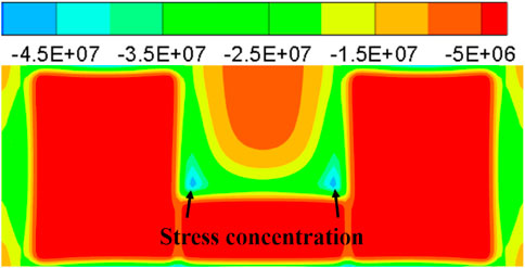
FIGURE 14. Distribution of advance abutment pressure during mining in a panel.
Figure 15 illustrates the stress distribution of a roadway for 21 m ahead of the N8102 panel. The peak stress in the 6 m coal pillar increased by 80% from 12.5 MPa to 22.5 MPa under the effect of advance abutment stress, which is greatly affected by the advance abutment stress.
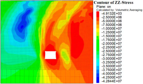
FIGURE 15. Stress distribution of roadway surrounding rock during mining.
As indicated in Figure 16, under the dual effect of advance abutment pressure and lateral abutment pressure, the roof subsidence of the roadway increases from 390 mm during roadway excavation to 568 mm, an increase of 46%. The maximum displacement of roadway coal pillar rib increases from 403 mm to 642 mm, an increase of 59%. The maximum displacement of the solid coal rib increases by 178 mm. The results display that the displacement of a surrounding rock increases considerably under the influence of advance abutment stress.
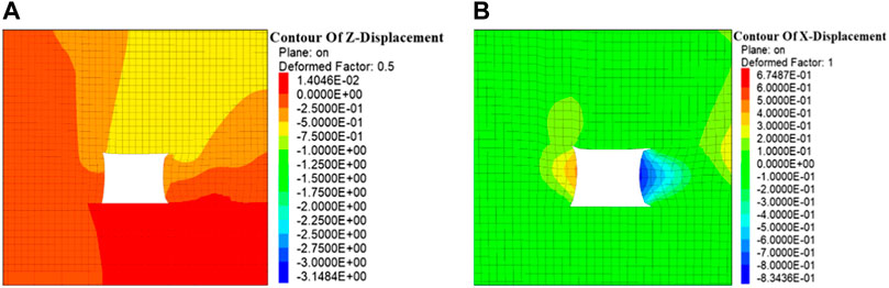
FIGURE 16. Deformation distribution in surrounding rocks during mining. (A) Vertical deformation; (B) Horizontal deformation.
Based on the analyses of stresses and displacements in surrounding rocks, 2102 tailgate is greatly affected by the mining of this panel, but the overall stress environment and displacement of surrounding rock can be stabilized within the controllable range through reasonable support. In the process of face mining, it is essential to focus on strengthening the support of the affected section of the advance abutment stress to ensure the roadway stability.
4 Determination of CPW
According to the simulation analyses in Section 3, the results indicate that the variation in CPW leads to stress and deformation distribution characteristics of surrounding rocks as shown in Table 2. Considering various influencing factors, although the bearing capacity is average, and surrounding rock has a certain deformation of 6 m coal pillar, the roadway deformation can be controlled in a safe range using a scientific surrounding rock control scheme.
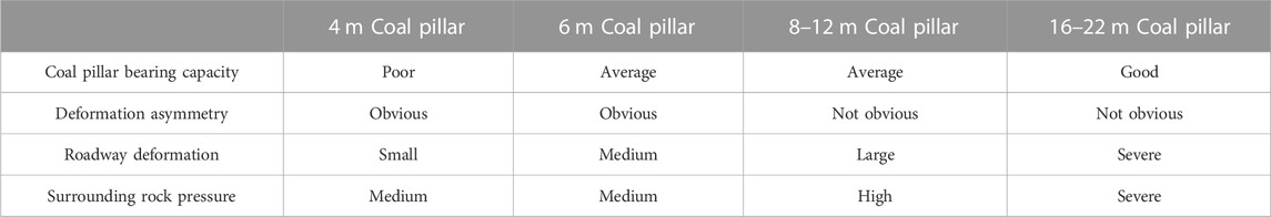
TABLE 2. Characteristics of surrounding rocks under various CPW.
5 Surrounding rocks control technology and engineering practice of gob-side entry
5.1 Support scheme
Base on the deformation characteristics of 2102 tailgate in N8102 isolated panel and simulation analysis of different CPW, the final asymmetric joint control technology of asymmetric anchor cable truss, high intensity anchor cable, and coal pillar grouting are employed to support a roadway. A diagrammatic drawing of specific roadway support is displayed in Figure 17.
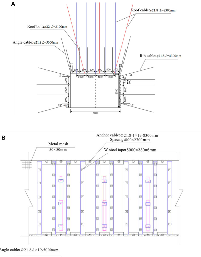
FIGURE 17. Diagrammatic drawing of roadway support. (A) Roadway support section; (B) Roadway support vertical view.
The solid coal rib is supported by anchor cables with a spacing of 1,000 mm x 900 mm. The anchor cables are installed perpendicular to roadway ribs, except for the anchor cables on the upper and lower sides which are installed at 15° to the vertical direction. The anchoring agent is MSZ2360 resin cartridge, with one anchor rope and one anchor rope. The size of the metal mesh used in the rib is 50 × 50 mm. A diagrammatic drawing of the solid coal rib support is shown in Figure 18.
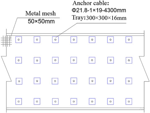
FIGURE 18. Solid coal rib support.
The coal pillar rib is set up with a row of anchor cables more than the solid coal rib. The anchor cables are Φ21.8–1 × 19–4,300 mm steel strand with row spacing of 1,000×900 mm. Each anchor cable adopts an MSZ2360 resin cartridge. To enhance the control of coal pillar ribs, C12 concrete with a thickness of 100 mm is used for grouting and spraying. A diagrammatic drawing of coal pillar rib support is displayed in Figure 19.

FIGURE 19. Coal pillar rib support.
5.2 Field verification
As illustrated in Figure 20, a maximum displacement between the roof and floor and between the two ribs during a roadway excavation are 198 mm and 149 mm respectively, which indicates that a roadway is well controlled using asymmetric combined support scheme.
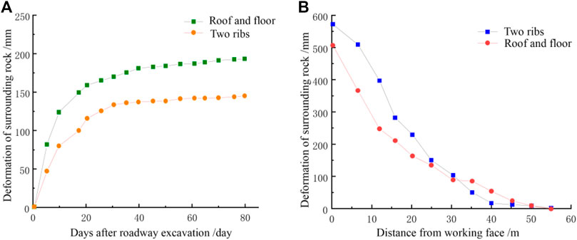
FIGURE 20. Displacement curve of a surrounding rock. (A) During roadway excavation; (B) During the mining of a panel.
During the mining of N8102 isolated panel, the maximum displacements between two ribs and between roof and floor are 575 mm and 508 mm respectively. The results suggest that the deformation on surrounding rocks during mining is greater than that during roadway excavation. Therefore, the impact of mining on the N8102 panel is more dramatic. However, the support elements in a roadway are still in a stable condition and a whole displacement of surrounding rock of a roadway is in a controllable range.
6 Conclusion
1) The peak stress in N8102 isolated panel is 32.9 MPa, and stress concentration factor is 2.99, which is more affected by the excavation of adjacent panel, and the peak stress on both sides is higher.
2) Through numerical simulation stress and displacement change characteristics of coal pillar ribs and solid coal ribs with different CPW, 6 m pillar width has better bearing characteristics and helps to maintain the durability of surrounding rocks.
3) According to the asymmetry of surrounding rock deformation, the final joint control technology of asymmetric anchor cables, high intensity anchor cables, and coal pillar grouting is proposed and get good control effect on site.
Data availability statement
The original contributions presented in the study are included in the article/supplementary material, further inquiries can be directed to the corresponding author.
Author contributions
XH: Conceptualization, Investigation, Data curation, Formal analysis, Writing—Original Draft. KY: Supervision, Resources, Writing—Review and Editing, Project administration, Funding acquisition. SH: Formal analysis, Investigation. YC: Writing—Review and Editing. RX: Writing—Review and Editing.
Funding
This paper was supported by the Key Projects of Natural Science Research in Anhui Universities (2022AH050839), National Program on Scientific Research Foundation for High-level Talents of Anhui University of Science and Technology (2021yjrc11), Key Basic Research Project of China (2019YFC1904304), Institute of Energy, Hefei Comprehensive National Science Center under Grant No. 21KZS217, National Natural Science Foundation of China (52130402). Independent Research fund of Joint National-Local Engineering Research Centre for Safe and Precise Coal Mining (Anhui University of Science and Technology) (EC2022021).
Conflict of interest
The authors declare that the research was conducted in the absence of any commercial or financial relationships that could be construed as a potential conflict of interest.
Publisher’s note
All claims expressed in this article are solely those of the authors and do not necessarily represent those of their affiliated organizations, or those of the publisher, the editors and the reviewers. Any product that may be evaluated in this article, or claim that may be made by its manufacturer, is not guaranteed or endorsed by the publisher.
References
Bai, J. B., Shen, W. L., Guo, G. L., and Yu, Y. (2015). Roof deformation, failure characteristics, and preventive techniques of gob-side entry driving heading adjacent to the advancing working face. Rock Mech. Rock Eng. 48 (6), 2447–2458. doi:10.1007/s00603-015-0713-2
Cai, M. F., He, M. C., and Liu, D. Y. (2013). Rock mechanics and engineering. 2nd. Beijing, China: Science Press.
Esterhuizen, G. S., Dolinar, D. R., and Ellenberger, J. L. (2011). Pillar strength in underground stone mines in the United States. Int. J. Rock Mech. Min. Sci. 48, 42–50. doi:10.1016/j.ijrmms.2010.06.003
Gao, F. Q., and Kang, H. P. (2016). Effects of pre-existing discontinuities on the residual strength of rock mass—Insight from a discrete element method simulation. J. Struct. Geol. 85, 40–50. doi:10.1016/j.jsg.2016.02.010
Gao, F. Q., Stead, D., and Kang, H. P. (2015). Numerical simulation of squeezing failure in a coal mine roadway due to mining-induced stresses. Rock Mech. Rock Eng. 48 (4), 1635–1645. doi:10.1007/s0060.3-014-0653-2
He, F. L., Li, X. B., He, W. R., Zhao, Y. Q., Xu, Z. H., and Li, Q. S. (2020). The key stratum structure morphology of longwall mechanized top coal caving mining in extra-thick coal seams: A typical case study. Adv. Civ. Eng., 1–13. doi:10.1155/2020/7916729
Itasca (2007). Fast Lagrangian analysis of continua in 3 dimension. Minneapolis, MN, USA: User’s guide.Version 3.1
Jawed, M., and Sinha, R. K. (2018). Design of rhombus coal pillars and support for roadway stability and mechanizing loading of face coal using SDLs in a steeply inclined thin coal seam—A technical feasibility study. Arab. J. Geosci. 11 (15), 1–14. doi:10.1007/s12517-018-3747-4
Kang, H. P., Lin, J., Yan, L. X., Zhang, X., and Wu, Y. Z. (2009). Study on characteristics of underground in-situ distribution in Shanxi coal mining fields. Chin. J. Geophys 52 (7), 1782–1792. doi:10.3969/j.issn.0001-5733.2009.07.012
Li, W. F., Bai, J. B., Peng, S., Wang, X. Y., and Xu, Y. (2014). Numerical modeling for yield pillar design: A case study. Rock Mech. Rock Eng. 48, 305–318. doi:10.1007/s00603-013-0539-8
Lisjak, A., and Grasselli, G. (2014). A review of discrete modeling techniques for fracturing processes in discontinuous rock masses. J. Rock Mech. Geotech. Eng. 6 (4), 301–314. doi:10.1016/j.jrmge.2013.12.007
Medhurst, T. P., and Brown, E. T. (1998). A study of the mechanical behaviour of coal for pillar design. Int. J. Rock Mech. Min. Sci. 35, 1087–1105. doi:10.1016/S0148-9062(98)00168-5
Poulsen, B. A. (2010). Coal pillar load calculation by pressure arch theory and near field extraction ratio. Int. J. Rock Mech. Min. Sci. 47 (7), 1158–1165. doi:10.1016/j.ijrmms.2010.06.011
Salamon, M. D. G., and Munro, A. H. (1967). A study of strength of coal pillars. J. S Afr. Inst. Min. Metall. 68, 55–67.
Salamon, M. D. G., Ozbay, M. U., and Madden, B. J. (1998). Life and design of bord-and-pillar workings affected by pillar scaling. J. S Afr. Inst. Min. Metall. 98, 135–145. doi:10.1016/S0925-8388(97)00629-4
Salamon, M. D. G. (1970). Stability, instability and design of pillar workings. Int. J. Rock MechMin Sci. Geomech. 7, 613–631. doi:10.1016/0148-9062(70)90022-7
Shen, B. T. (2013). Coal mine roadway stability in soft rock: A case study. Rock Mech. Rock Eng. 47, 2225–2238. doi:10.1007/s00603-013-0528-y
Si, G. Y., Jamnikar, S., Lazar, J., Shi, J. Q., Durucan, S., Korre, A., et al. (2015). Monitoring and modelling of gas dynamics in multi-level longwall top coal caving of ultra-thick coal seams, part I: Borehole measurements and a conceptual model for gas emission zones. Int. J. Coal Geol. 144 (145), 98–110. doi:10.1016/j.coal.2015.04.008
Tewari, S., Kushwaha, A., Bhattacharjee, R., and Porathur, J. L. (2018). Crown pillar design in highly dipping coal seam. Int. J. Rock Mech. Min. Sci. 103, 12–19. doi:10.1016/j.ijrmms.2018.01.012
Wang, E., and Xie, S. R. (2022). Determination of coal pillar width for gob-side entry driving in isolated coal face and its control in deep soft-broken coal seam: A case study. Energy Sci. Eng. 10 (7), 2305–2316. doi:10.1002/ese3.1139
Wang, S. L., Hao, S. P., Chen, Y., Bai, J. B., Wang, X. Y., and Xu, Y. (2016). Numerical investigation of coal pillar failure under simultaneous static and dynamic loading. Int. J. Rock Mech. Min. Sci. 84, 59–68. doi:10.1016/j.ijrmms.2016.01.017
Wu, W. D., Bai, J. B., Wang, X. Y., Yan, S., and Wu, S. X. (2018). Numerical study of failure mechanisms and control techniques for a gob-side yield pillar in the Sijiazhuang coal mine, China. Rock Mech. Rock Eng. 52 (4), 1231–1245. doi:10.1007/s00603-018-1654-3
Yang, S. Q., Chen, M., Jing, H. W., Chen, K. F., and Meng, B. (2017). A case study on large deformation failure mechanism of deep soft rock roadway in Xin'An coal mine. China. Eng. Geol. 217, 89–101. doi:10.1016/j.enggeo.2016.12.012
Yu, B., Zhang, Z. Y., Kuang, T. J., and Liu, J. R. (2016). Stress changes and deformation monitoring of longwall coal pillars located in weak ground. Rock Mech. Rock Eng. 49, 3293–3305.
Keywords: coal pillar, stress and displacement, roadway support, isolated panel, extra-thick coal seam
Citation: He X, He S, Cai Y, Xu R and Yang K (2023) Investigation on rational width of coal pillar and roadway support in isolated panel of extra-thick coal seam. Front. Earth Sci. 11:1125678. doi: 10.3389/feart.2023.1125678
Received: 16 December 2022; Accepted: 20 January 2023;
Published: 10 February 2023.
Edited by:
Yingfeng Sun, University of Science and Technology Beijing, ChinaReviewed by:
Jiliang Pan, University of Science and Technology Beijing, ChinaHuining Ni, China University of Mining and Technology, China
Wang Qun, Taiyuan University of Technology, China
Copyright © 2023 He, He, Cai, Xu and Yang. This is an open-access article distributed under the terms of the Creative Commons Attribution License (CC BY). The use, distribution or reproduction in other forums is permitted, provided the original author(s) and the copyright owner(s) are credited and that the original publication in this journal is cited, in accordance with accepted academic practice. No use, distribution or reproduction is permitted which does not comply with these terms.
*Correspondence: Ke Yang, a2V5YW5nMjAwM0AxNjMuY29t