 Hongwei Wang1,2,3
 Baolin Jiang
95% of researchers rate our articles as excellent or good
Learn more about the work of our research integrity team to safeguard the quality of each article we publish.
Find out more
ORIGINAL RESEARCH article
Front. Earth Sci. , 20 February 2023
Sec. Structural Geology and Tectonics
Volume 11 - 2023 | https://doi.org/10.3389/feart.2023.1115323
This article is part of the Research Topic Multiple Field/Scale Rock Mechanics in Coordinated Exploitation of Coal and its Associated Resources View all 11 articles
The coal water co-mining of shallow coal seams in the loess gully area of Northern Shaanxi is affected by the coupling effect of overburden rock structure and topography. The development characteristics of mining fracture are complex and can induce mining and environmental disasters. To predict the disaster formation, taking the 113101 working face of the Kunyuan Coal Mine as the engineering background, numerical simulation, physical similarity simulation experiment, and theoretical analysis methods were used to analyze the mining gully of a shallow coal seam in a loess gully area. Based on the dynamic evolution characteristics of stress at different locations, the formation positions, dynamic development, and evolution processes of various fractures were studied; disaster-causing mechanisms were revealed and comprehensive methods were proposed. The results showed that in across-gully mining, the maximum horizontal compressive stress at the bottom of Gully No. 2 was approximately 20.00 MPa, the maximum horizontal tensile stress of the reverse slope section was approximately 1.50 MPa, the width of the F5 fracture of Gully No. 2 was 46.00 cm, and the elevation difference was up to 52.00 cm. The working face across-gully mining formed tensile fractures in most areas, collapsed fractures at the gully bottom, and extruded fractures in the reverse slope section. The fracture at the gully bottom could easily induce water–sand inrush and roof caving and supports crushing. The slope fracture could also induce a gully-induced landslide. According to the mechanisms and distribution areas of fracture disasters, the disaster areas were divided into water–sand inrush areas at the gully bottom, roof caving and supports crushing areas at the gully bottom and at the base of the slope section, and landslide areas at the upper part of the slope section and reverse slope section. Appropriate prevention and control measures were proposed, such as the upstream interception of surface water, slope reinforcement in the middle and upper part of the downhill section, artificial precracking of the roof in the middle and upper part of the downhill section, and grouting reinforcement at the gully bottom and slope toe of the downhill section. These measures were proven to effectively guarantee the safe and efficient mining efficiency of the working face.
The Yushenfu (Yulin, Shenmu, and Fugu) mining area has two major characteristics: 1) the surface gullies are crisscrossed, the elevation difference is large, and hydrological conditions are complex, which differ from the evolution process of overburden breaking and transporting and cause all kinds of mining disasters to occur irregularly, which greatly affects the safe mining of underground coal resources; 2) the ecological environment is extremely fragile, characterized by drought, little rain, and low vegetation cover, and across-gully mining is prone to environmental disasters, such as gully breakage, vegetation death, and soil desertification, which seriously affects the fragile ecosystem balance of the loess gully areas. Therefore, it is important to study the law of overburden breaking and transport of coal water co-mining, analyze the dynamic evolution of fractures, predict the occurrence of disasters, and protect the ecological environment.
In 1992, China’s geological scientists raised the issue of water protection mining. Over the past 20 years, scientists in the fields of geology, mining, ecology, and environment have explored and researched the issue of water conservation coal mining from multiple angles, initially establishing a water protection mining technology system, and significant progress has been made in engineering practice.
Coal water co-mining is the rational exploitation of two resources under the premise of water conservation, security, and environmental protection (Bai et al., 2009). After the concept and connotation of “coal-water” dual-resource mining were summarized, the technology and method of “coal-water” dual-resource mining were proposed (Gu et al., 2016; Wu et al., 2017). Mine water in the northwest of China’s arid and semi-arid climate zone is characterized by high mineralization, which requires the use of desalination methods, such as distillation, ion exchange, membrane separation, and biological treatment, to reduce the mineralization, as well as to remove acids, suspended solids, trace elements, radioactivity, and toxic and hazardous substances (Sun et al., 2020; Gu et al., 2021). Lin et al. (2020) studied the spatial characteristics and regional differences of water use in coal mines of China and pointed out that coal production in Shaanxi uses more water and has higher coal-related wastewater emissions than in other areas. Zhang et al. (2021) found that longwall mining has an impact on groundwater levels, thereby affecting the growth of surface vegetation.
Researchers have carried out a series of studies on the formation and development of fissures in across-gully mining and achieved outstanding results. Wang et al. (2016) studied overburden transport and fracture development using empirical equations, physical similar simulations, and numerical simulations to determine the height of the overburden mining collapse zone and ensure the safe mining of shallow buried coal seams in gully terrain. Liu (2014) classified mining cracks in the gully area into tensile cracks, extrusion cracks, collapse cracks, and sliding cracks and analyzed their formation mechanisms. Li (2021) analyzed the linkage between the development and distribution characteristics of overburden fractures and overburden activities in shallow buried thick coal seam mining in the gully area. The number of mining fractures in the downhill section of mining overburden was less than that in the uphill section, while the width of fractures showed an opposite trend. Repeated mining leads to fracture activation development. Che et al. (2021) and Hou et al. (2021a); Hou et al. (2021b) used physically similar simulation experimental methods to analyze the development rules of the location and spacing of surface cracks in shallowly buried coal seams in the gully area and classified the surface cracks into three types: down-slope pushing cracks, reverse-slope tensioning cracks, and gully bottom uplift, based on the relationship between slope direction and mining direction, and concluded that overburden destruction and surface morphology jointly formed surface cracks. Zhang (2016) established a main roof cycle breaking trapezoidal load mechanics model for across-gully mining and analyzed the influence of gully geomorphology on fracture development. They found that the development of fractures in the gully slope and back groove slope bodies showed a trend of inversion toward the gully. The back groove slope body appeared with the gully slope body reverse tensile fractures, with the fractures developing gradually upward from the gully bottom to the top of the back groove. In contrast, the fractures in the back groove slope body developed downward and the slope body inverted toward the extraction areas. This inversion of the back groove slope body caused the formation of stable structures in the deep part of the overburden rock. Both Wang et al. (2022) and Wei et al. (2022) used PFC numerical simulation to analyze the dynamic development process of fractures, by which microfractures are first generated, extended and expanded, then agglomerated into clusters, and, finally, become fractures. This process can be divided into three stages of development: discontinuous jumping, continuous transverse extension, and lateral expansion. Wang et al. (2020) studied the overburden movement and stope stress evolution laws in the process of longwall mining through faults via Universal Distinct Element Code (UDEC) numerical simulation, theoretical analysis, and field measurement. These studies revealed the development characteristics and evolution process of overburden fractures in coal seam mining in gully areas.
The height of the overburden fractured zone determines whether water from the mine aquifer and the surface will have an impact on mining (Zhang et al., 2018). Liu (2014) studied the influencing factors and characteristics of mine water influx under different geological conditions and obtained different prediction methods for water influx simulation. Luo and Fan (2015) and Fang and Xia (2018) analyzed the possibility of occurrence of sudden water and sand collapse disasters at each stage of mining and formulated three-dimensional water damage control measures above and below the well in the gully area. Jiang et al. (2017) divided four types of areas by GC (the ratio of bedrock to mining height), namely, water–sand inrush areas, water inrush areas, seepage areas, and water retention areas, and formulated reasonable water retention measures for each. Wei et al. (2022) analyzed the amount of surface gully water gushing into the mining area along the fracture under different conditions through UDEC and COMSOL numerical simulation experiments. Li et al. (2020) analyzed the mining gully channel flood filling mode of over-gully mining of shallow buried coal seam in loess hills, gave the formula for calculating the normal and maximum water gushing under the working face production flow-sink-seepage filling mode, and proposed corresponding water prevention and control measures. Chen (2020), Li (2013), and Chen (2015) analyzed the distribution law of “falling and fracture zones” on the roof of shallow buried coal seam across-gully mining, developed a prediction method of burst water volume and a zoning method of burst water hazard, revealed the mechanism of water–sand inrush under the action of multiple factors, and proposed technical measures of water–sand inrush prevention and control. Dong et al. (2021) analyzed water hazards caused by fractured zones in Northwest China. The aforementioned studies mainly revealed the mechanisms of water disasters induced by fracture development of shallow buried coal seam across-gully mining and formed water disaster prediction, zoning, and prevention measures. Disasters other than water disasters may be triggered by shallow buried coal seam mining in the gully area; therefore, it is necessary to study the different disasters that may occur in different locations in the gully area and judge the possible interconnection of each disaster to predict and manage water coal co-mining disasters under gullies.
This paper aims to predict possible induced disasters and carry out zoning and comprehensive management by studying the dynamic evolution characteristics of overburden stress, overburden fracture, and surface crack development in coal water co-mining under gullies using numerical simulations and physically similar simulation experiments, with the engineering context of the Kunyuan Coal Mine 113101 working face. This study provides reference for the prevention and control of coal water co-mining disasters under gullies and is based on the research background of coal and water co-mining.
The Kunyuan Coal Mine belongs to Daliuta Town, Yulin City, Shaanxi Province, China, and is located in the northern part of the Loess Plateau in Northern Shaanxi Province, at the southeastern edge of the Maowusu Desert. The geomorphological unit is a typical loess hilly area, and the surface is basically covered by wind-bound sand. The gullies are deep in the bedrock, and the branch gullies are very well developed. There are two gullies crossing the surface of 113101 working face from northwest to southeast (Figure 1). Gully No. 1 is a wash gully, with average slope angles of 35.82° and 35.30° for the downhill and uphill sections, respectively (the downhill section is the side of the slope where the thickness of the overburden rock gradually decreases along the direction of advancement, and the opposite for the uphill section). There is a large weathering zone and burned rock on the east side of the slope and water flow in the gully all year, with an average flow rate of 197.30 m3/h. Gully No. 2 is a cut gully, with average slope angles of 28.44° and 21.59° for the downhill and uphill sections, respectively. There is water flow only in the rainy season. Long-term water erosion has destroyed the structural integrity of the overburden rock, and two weathering erosion zones with vertical depths of 0.2–4.3 m have formed along the riverbed.
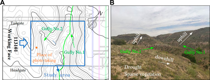
FIGURE 1. Spatial distribution of the study area and gullies, including (A) the relative position of the working face and gully and (B) photos of gully surface morphology.
The 113101 working face is mainly mining a 3–1 coal seam with a buried depth of 29.36–91.80 m. The lowest depth of the coal seam in Gully No. 1 is 7.49 m, compared to 16.42 m in Gully No. 2. The average thickness of coal seam is 1.81 m, the structure is simple, and the bottom contains a stratum of gangue. The immediate roof is gray, gray–white mudstone, and sandy mudstone, with mud cementation and lamination development, containing a small amount of mica and plant fossils, and belongs to class III immediate roof; the main roof is gray and gray–white dense coarse-grained sandstone, with mud cementation and wavy lamination development, containing plant fossils, and belongs to class II main roof; and the floor is mainly gray and gray–white dense coarse-grained sandstone with mud cementation. The physical and mechanical parameters of the coal rock are shown in Table 1. The working face is 776 m in trend length and 280 m in inclination length. A longwall comprehensive mechanized coal mining method and natural collapse method are used to manage the roof, with a mining height of 1.80 m, five cycles of daily coal cutting, and a cut-off depth of 0.8 m. The purpose of coal water co-mining at working face 113101 is to recycle and utilize mine water, divert surface rivers, and restore the surface ecology of the mine area as much as possible after mining. As shown in Figure 2, the exploitation of water resources is divided into two parts: damming the surface to intercept the flow and pumping water in the collecting drain of goaf. The dam is located upstream of the first gully, 50 m from the tailgate of 113101 working face. The water collecting drain is advanced in the floor of the goaf in the middle of Gullies No. 1 and 2 and the water collecting drain is advanced in the floor at 30 cm in height and covered with a six-mesh screen.
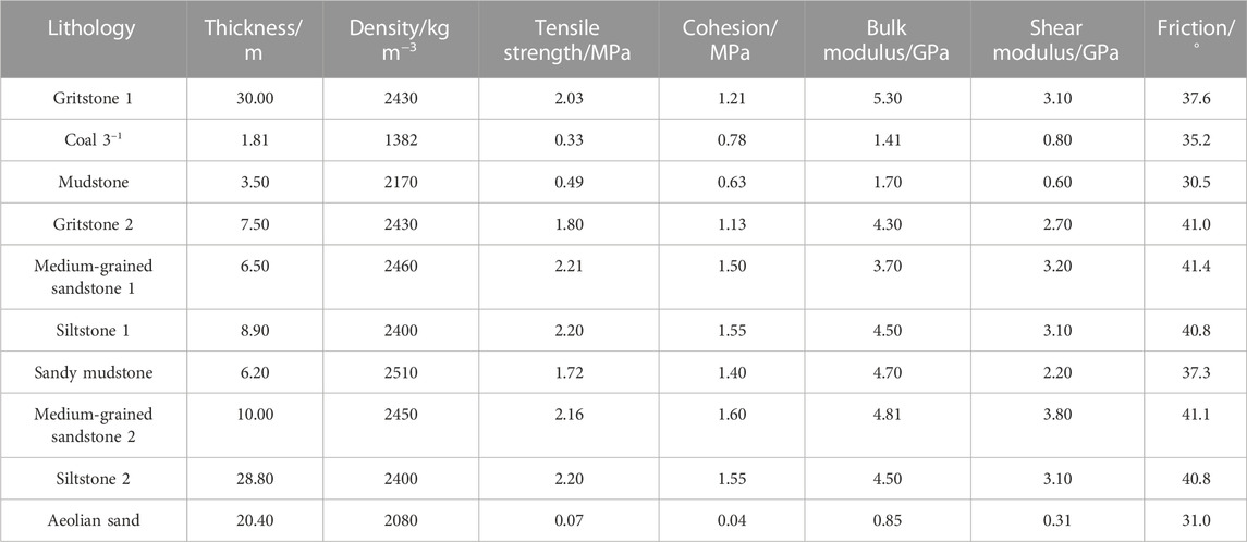
TABLE 1. Mechanical parameters of rock strata.
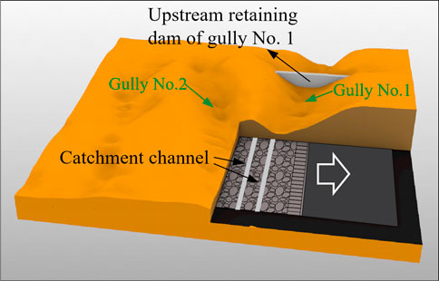
FIGURE 2. 3D conceptual model of the 113101 working face, reflecting the concept of coal water co-mining underground and on the surface.
Taking the Kunyuan Coal Mine 113101 working face as the engineering background, according to the engineering, geological, and production conditions as well as the physical and mechanical parameters of coal rocks (Table 1), a 3D model of the surface gully was established by Rhino software. Then, the grid was divided by Griddle and imported into FLAC3D software to generate a 3D numerical simulation model (Figure 3). The model size was L × W × H = 620 m × 580 m × 102 m, with 144,853 grid points and 795,173 cells. The Mohr–Coulomb principal structure model with large deformation stress mode was used. Taking the B–B section as reference, we analyzed the overburden stress evolution characteristics of shallow buried coal seam mining through the downhill section of Gully No. 2 (X = 190–270 m), uphill section of Gully No. 2 (X = 270–330 m), downhill section of Gully No. 1 (X = 330–390 m), and uphill section of Gully No. 1 (X = 390–535 m) to reveal the overburden transport law.
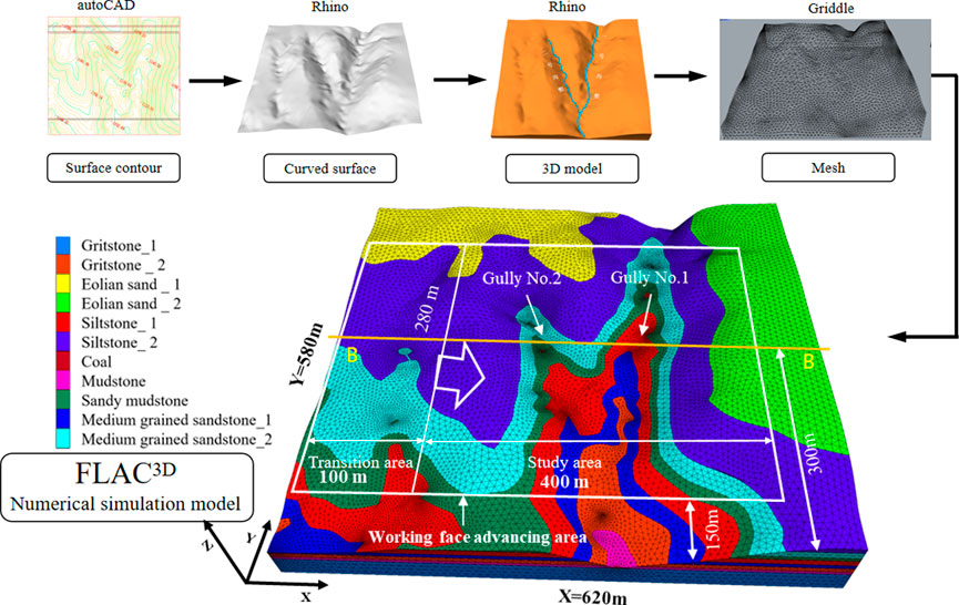
FIGURE 3. Establishment process from surface contour to 3D drawing, 3D mesh model, and FALC3D numerical simulation model.
The maximum principal stress distribution of the B–B section when the working face advances to Gully No. 2 (X = 190–332 m) is shown in Figure 4. The direction and size of the maximum principal stress deflection indicates that the overburden rock above the mining area formed a stress arch structure, with the rock strata below the stress arch in a stress release state and the rock strata above the “stress arch” in a compressive stress concentration state. This stress distribution state causes the surface behind the working face to be subjected to tensile stress, which is expressed as extrusion, and the surface above the working face to be subjected to tensile stress, which is expressed as tension. Specially, the bottom of Gully No. 2 was subjected to strong tensile stress effect for a long time and the effect was obvious, and the details are as follows.
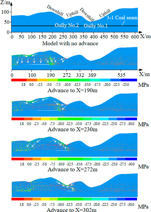
FIGURE 4. Distribution and transfer path of maximum principal stress in section B–B, with the working face advancing to X = 190 m, X = 230 m, X = 272 m, and X = 302 m.
The stress transfer law in Gully No. 1 was approximately the same as that in Gully No. 2. The details of the dynamic changes of the maximum principal stress during the advance of Gully No. 2 were as follows. As shown in Figure 5, the working face was advanced to X = 190 m. According to the route of maximum principal stress transmission, the stress arch was in the shape of a “saddle,” similar to the shape of the surface, the overburden rocks above the stress arch were subject to compressive stress, and the overburden rocks below the stress arch were subject to tensile stress. From the surface stress situation, the back of the working face was subjected to compressive stress and the front of the working face was subjected to tensile stress, in which the concentration of tensile stress at the bottom of Gully No. 2 was the most obvious, with a maximum value of 1.83 MPa.
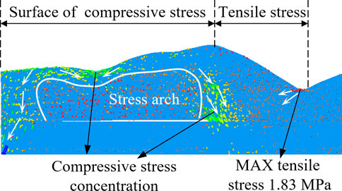
FIGURE 5. Shape of stress arch and the distribution characteristics of maximum principal stress when advancing to 190 m, and the maximum tensile stress of 1.83 MPa, located at the bottom of Gully No. 2.
As shown in Figure 6, when the working face was advanced to 272 m, the stress arch shape returned to normal. Taking the gully bottom as the boundary, the surface behind the working face showed obvious compressive stress concentration and that in front of the working face showed tensile stress concentration. Currently, the most complicated changes were in the gully bottom and the magnitude of stress changes was large, making it easy for the overburden rock to collapse with obvious elevation difference in the gully bottom.
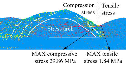
FIGURE 6. Shape of the stress arch and the distribution characteristics of maximum principal stress when advancing to 272 m; the maximum tensile stress is 1.84 MPa, and the maximum compressive stress is 29.86 MPa, both located at the bottom of Gully No. 2.
In summary, the macroscopic stress transfer path was as follows: first, the stress behind the working face was transferred to both sides along the trend and the stress transferred to the working face was arched, resulting in the concentration of compressive stress behind the working face; then, the stress in front of the working face was transferred to the working face, and the tensile stress was concentrated in front of the working face; finally, the stress in the downhill and uphill sections above the goaf was transferred to the gully bottom.
When the working face was advanced to X = 280 m, the horizontal extrusion stress was concentrated in the lower part of the downhill section of Gully No. 2 and the gully bottom, the maximum horizontal extrusion stress was 4.68 MPa, the maximum horizontal tensile stress in the uphill section was 1.53 MPa. The downhill section of Gully No. 2 was above the goaf, and sliding fractures would be formed throughout the downhill section while extrusion fractures would only be formed at the base of it. The uphill section was above the coal and contained over-extension fractures as shown in Figure 7A. When the working face was advanced to X = 340 m, the horizontal extrusion stress at the bottom of Gully No. 2 was 8.00–12.00 MPa and the stress state changed from tensile stress to minor stress to compressive stress. The fractures healed or changed types to form other fractures, as shown in Figure 7B. When the working face was advanced to X = 410 m, a small range of horizontal compressive stress was concentrated in the lower part of downhill section of Gully No. 1, the maximum compressive stress was 6.00 MPa, the formed fractures were easily healed to varying degrees, a small range of horizontal compressive stress was concentrated in the lower part of the uphill section of Gully No. 1, the maximum horizontal tensile stress was 1.75 MPa, and tensile fractures were prone to form along the weak surface of rock joints, as shown in Figure 7C. When the working surface was advanced to X=460 m, horizontal extrusion stress concentration occurred at the bottom of Gully No. 1, and extrusion and collapse fractures formed at the base of the slope. The loose layer and weathering zone of the uphill slope body of Gully No. 1 were staggered with the bedrock under the action of tensile stress, which made it easier for sliding fractures to form, as shown in Figure 7D.
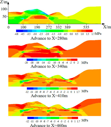
FIGURE 7. Evolution characteristics of XX stress of section B–B with the working face advancing to X = 280 m, X = 340 m, X = 410 m, and X = 460 m.
The horizontal stress of the surface first increased and then decreased during across-gully mining. The horizontal stress of the surface was 2.11–4.02 MPa in the downhill section and 5.92–17.35 MPa in the uphill section. The surface of the gully was in a horizontal compressive stress state far from the working face, as shown in Figure 8A. The vertical tensile stress of the surface first increased and then decreased. The vertical tensile stress at the surface of Gully No. 2 was 0.69–3.74 MPa, with the vertical stress at the surface being the largest across the gully. The vertical tensile stress at the surface of Gully No. 1 was 0.69–1.56 MPa and the uphill section was in a vertical compressive stress state behind the working face, as shown in Figure 8B. The vertical tensile stress reflected to the overburden collapse state and the tensile stress range in front of the working face included the overburden fracture development and overbreak areas. The tensile stress range in the gully area included the collapse fracture development area. The bottom of Gullies No. 2 and 1 was in a high-tensile stress state, which encouraged collapse fractures.
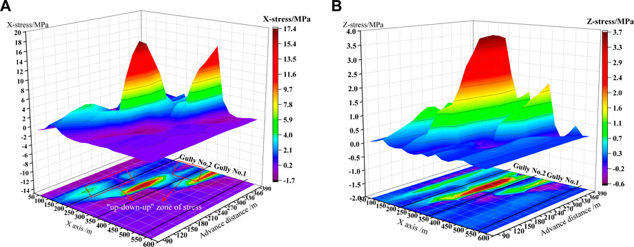
FIGURE 8. Stress distribution characteristics of certain surface measuring points on the B–B section when advancing to certain distances: (A) horizontal stress and (B) vertical stress.
The aforementioned research was based on FLAC3D numerical simulation to study the across-gully mining of coal water co-mining mine. The stress state of each area at different stages of advancement was obtained from the path of stress transfer, and the stress state of each area was obtained from the characteristics of stress distribution, which reflects the possible fractures and the movement trend of overburden. However, there are major limitations for using finite element methods to study rock breaking and fracture development. Its displacement field cannot directly analyze the dynamic development of fractures, so it is difficult to predict disasters. Currently, PFC numerical simulation is commonly used to analyze the stress field, displacement field, and force chain transmission law. However, this method requires the establishment of small particles, consumes a lot of memory and CPU computing power, and requires the selection of a constitutive model suitable for the rock strata to reasonably analyze and determine various parameters in theory. Much more research still needs to be carried out, and it is difficult to obtain scientific research results in a short time. Therefore, this study chose to conduct physical similarity simulation experiments to supplement the study and further investigate the overburden transport characteristics, fracture development, and evolution process, to predict possible disasters.
To verify the numerical simulation results and further determine the dynamic development process of fractures in across-gully mining, a 2D physically similar simulation model was established based on the B–B section (Figure 9), with a geometric similarity ratio of 1:200, capacity similarity ratio of 0.64, stress similarity ratio of 3.2 × 10⁻³, and similar material ratios for each rock strata, as shown in Table 2. The model dimensions were L × W × H = 2000 × 200 × 506 mm. The coordinate system of the physically similar simulation model and the numerical simulation model were the same, and the coordinates of the lower left corner of the physically similar simulation model were X = 140 m and Z = 20 m) The left end of the model had no contact with the model frame and the model was advanced 20 cm to simulate the goaf in front of gully to avoid the error caused by the left boundary of the model.
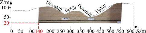
FIGURE 9. Location of the physical similarity simulation model and section B–B.
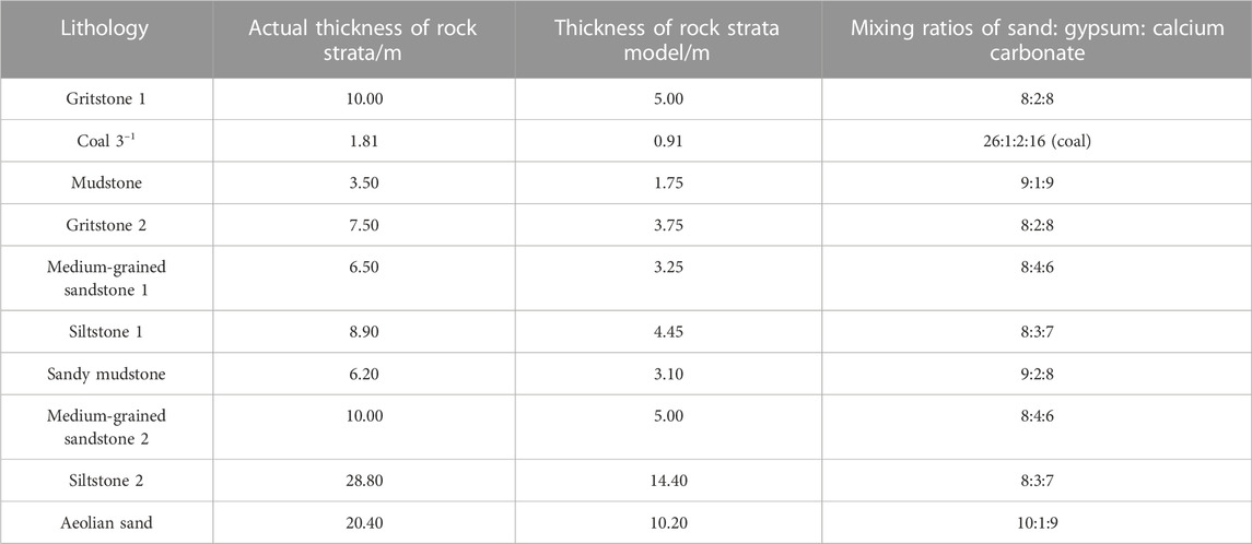
TABLE 2. Similar material ratio for rock strata.
When the working face advanced to X = 230 m, tensile fracture F2 developed to the top downhill section of Gully No. 2, the overburden breakage angle was 120°, and the topmost loess of the model was destroyed into seven parts of different sizes, with length ranging from 3.0 to 5.6 cm (Figure 10A). When the working face advanced to X = 250 m, the immediate roof collapse and main roof breakage caused the overburden rock to form a big intact rock. The center of gravity of this rock mass shifted above the mining areas, which led to the expansion of tensile fracture F4, the formation of tensile fracture F3, and the narrowing of fracture F2 (Figure 10B); fracture F4 was located at the base of the downhill section of Gully No. 2, which connected Gully No. 2 with the goaf and became a water–sand inrush channel. The formation of the big intact rock indicated that the overburden load decreased after the overburden thickness decreased, which led to the change of cycle collapse distance, and fractures were formed in the thin bedrock with low strength and weak surface as the working face advanced.
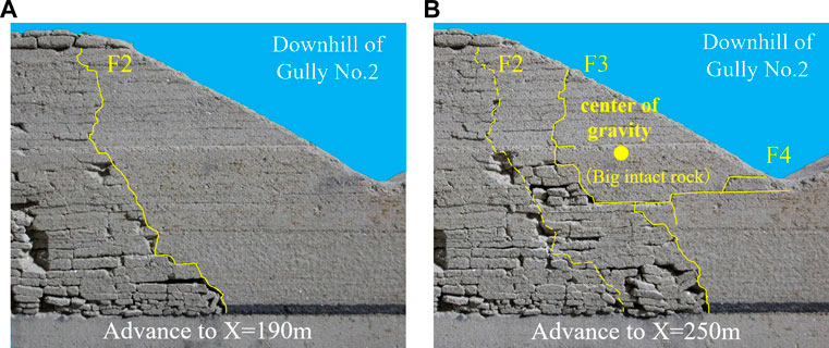
FIGURE 10. Characteristics of fracture development and overburden migration when advancing to (A) X = 190 m and (B) X = 250 m.
As shown in Figure 11, when advancing to X = 270 m, the working face was located below the bottom of Gully No. 2. The surface rift F4 broke downward, forming a break line of approximately 5 cm long, and stopped developing at 11.2 cm above the working face. In addition, a new break line developed from the bottom of Gully No. 2 downward, which exceeded the working face by 10.3 cm, called an overburden overbreak line. This line stopped developing at 6.1 cm above the working face and was the prototype of fracture F5. When the working face advanced to X = 280 m, the overburden overbreak line developed into collapse fracture F5, which penetrated the overburden to the working face from the surface. At this point, the overburden rock was cut off above or in front of the hydraulic supports, which caused the collapsed roof to press on and damage the supports. The width of fracture was approximately 1.8 mm, the elevation difference between both sides of fracture was approximately 2.6 mm, and a fracture with width of 2.3 mm and elevation difference of 2.6 mm was formed on the surface. In addition, the secondary development of fracture F3 occurred with the formation of fracture F5. When the working face advanced to X=290 m, tensile fracture F6 was formed and the width and elevation difference of fracture F5 were reduced to 0.6 and 1.1 mm, respectively. Fracture F6 was formed by tensile damage but showed the characteristics of collapse fracture at its surface. The width of surface fracture was 1.5 mm and elevation difference was 0.9 mm, which was presumed to be caused by the rotation of broken overburden to goaf. When the working face was advanced to X = 310 m, tensile fracture F7 was formed, and fractures F5 and F6 and the surface fractures were basically healed.
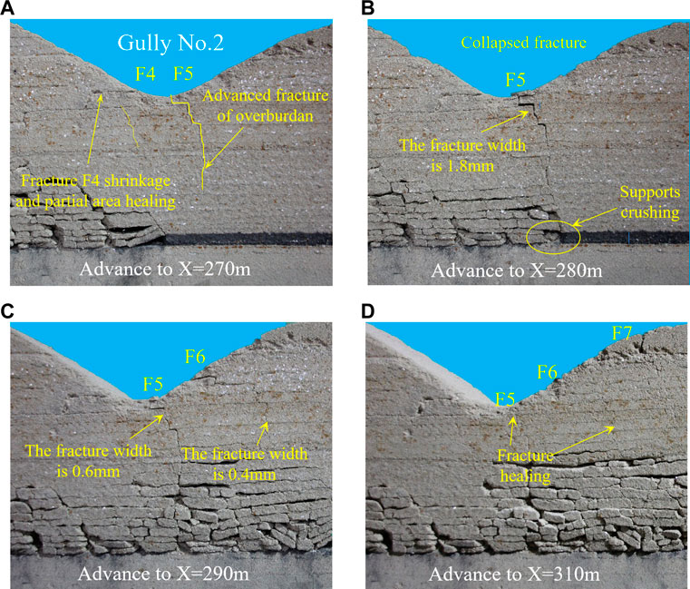
FIGURE 11. Characteristics of fracture development and overburden migration when advancing to (A) X = 270 m, (B) X = 280 m, (C) X = 290 m, and (D) X = 310 m.
As shown in Figure 12, when the working face advanced to X = 330 m, it entered the downhill section of Gully No. 1 and tensile fracture F8 was formed, forming fractures on the surface. When the working face advanced to X = 350 m, the upper part of fracture F8 narrowed, the surface fractures healed, and the lower part showed secondary expansion; tensile fracture F9 was formed in front of the working face, which overshot the working face by 6.4 cm and was located at the base of the downhill section of Gully No. 1; another big intact rock was formed between fractures F8 and F9. The load of this rock was transferred to supports, which crushed the supports. When the working face advanced to X = 370 m, fractures F8 and F9 narrowed and collapse fracture F10 was formed at the base of the downhill section, which went straight from the surface to the working face and caused support crushing and water–sand inrush. In addition, the fracture F10 formed a surface crack with an elevation difference of 0.37 mm. The left side of this surface crack sank, and the right side was elevated, that is, the left side showed a collapse fracture and the right side showed an extrusion fracture. It is presumed that the overburden rock was caved and formed a collapse fracture, then the broken rock strata and the big intact rock in the back goaf deflected toward the working face, resulting in the left side of fracture F10 squeezing the right side and creating a collapse-extrusion surface crack on the surface near collapse fracture. When the working face was advanced to X = 390 m, tensile fracture F11 was formed, the overburden elevation difference between the two sides of fracture F10 was obviously reduced, and the surface fracture was healed to some extent; however, the extruded and lifted rock on the right side was still higher than the surrounding surface.
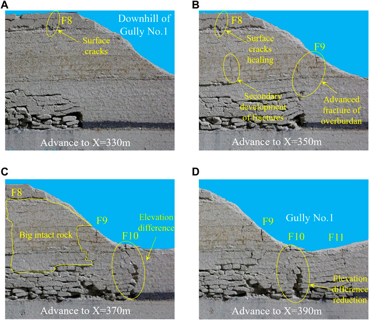
FIGURE 12. Characteristics of fracture development and overburden migration when advancing to (A) X = 330 m, (B) X = 350 m, (C) X = 370 m, and (D) X = 390 m.
As shown in Figure 13, when the working face advanced to X = 410 m, tensile fracture F12 was formed and fracture F11 showed no obvious change. When the working face advanced to X = 430 m, tensile fracture F13 was formed, fracture F11 was narrowed, fracture F12 mostly healed, and both surface cracks disappeared. When the working face advanced to X = 450 m, tensile fracture F14 was formed, fracture F13 shrank, and the surface fracture healed. When the working face advanced to X = 470 m, a large collapse space was formed after the main roof collapsed, which led to further collapse and compaction of the collapsed rock strata on the left side of fracture F14. Fracture F14 was transformed into a collapse fracture and the elevation difference between the two sides of the fracture was 0.22 mm, forming a tensile-collapse crack on the surface.
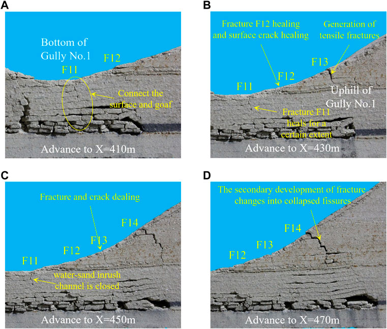
FIGURE 13. Characteristics of fracture development and overburden migration when advancing to (A) X = 410 m, (B) X = 430 m, (C) X = 450 m, and (D) X = 470 m.
The fractures in different areas had distinct characteristics, shown in Table 3. The fractures healed more easily in the gully bottom, while the junction between the base downhill section and gully bottom was most likely to collapse; the fracture formation of the slope body with obvious change of overburden thickness tended to be lagging behind and the fracture formation in the downhill section tended to form a big intact rock after the fracture formation was lagging behind. The fracture formation lagging behind in the uphill section tended to trigger the secondary development of the existing fractures and turned into collapse fractures. The distribution of each type fracture and the dynamic development of representative fractures are shown in Figure 14.
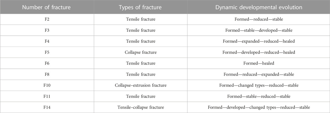
TABLE 3. Dynamic developmental and evolutionary characteristics of representative fractures.
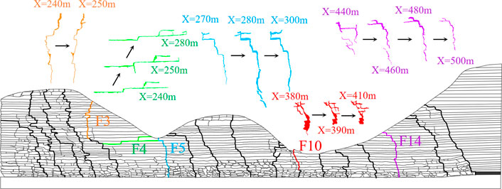
FIGURE 14. Distribution of all fractures and dynamic development of representative fractures (F3, F4, F5, F10, and F14)
Possible disasters that can occur during the mining of the 113101 working face are water–sand inrush, roof caving and supports crushing, and gully-induced landslide. The formation mechanisms of these disasters are as follows.
The formation of water–sand inrush requires: 1) fractures connecting the surface and the working face (goaf); and 2) that water and sand can flow into the above fractures.
When the rock strata under the cover of water and sand in Gullies No. 1 and 2 produce tensile and collapse fractures that go straight through the goaf or working face, water and sand flow into the goaf or working face along these fractures, resulting in water–sand inrush disasters, as shown in Figure 15.
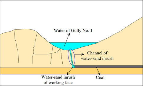
FIGURE 15. Formation mechanisms of water–sand inrush; channel that connects water and the working face (goaf).
When the working face advances to the gully bottom, due to the incomplete structure of the overburden rock, it is eroded by running water while the hard rock strata, such as the key strata, are eroded. The rock strata are small in thickness and low in strength, and collapse fractures are easily produced above the working face, such as fractures F5 and F10. After the formation of such fractures, the load of the broken overburden above the working face acts on the hydraulic supports. The strong mine pressure causes the hydraulic supports to be crushed (shown in Figure 16), which can cause coal wall spalling, equipment damage, and casualties.
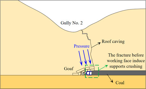
FIGURE 16. Formation mechanisms of roof caving and supports crushing; fractures are formed in front of or above the supports.
There are loess and aeolian sands on the slope body and slope top of Gullies No. 1 and 2, and there is a weathering erosion zone with a height of 0.2–4.3 m at the slope toe, thus forming the characteristics of weak slope base and heavy slope body. When a mining fracture develops to the slope, the disturbed loose layer (loess and aeolian sand) is damaged and destabilized, forming a slope instability landslide. When the mining-induced fractures develop to the weathering erosion zone at the slope toe, the slope toe structure is destroyed, the supporting point of the slope disappears, and the loess and aeolian sand on the slope slide to the gully bottom under the action of gravity, forming a landslide of slope instability. When the working face is pushed through the gully bottom, if collapse fractures are generated at the gully bottom and toe of the slope, the slope foundation structure is missing, forming a landslide of base slope loss. In general, the probability of landslides in the downhill section is low and the impact on the working face is high. In contrast, the probability of landslides in the uphill section is high and the impact on the working face is low.
In simple terms, any crack under the water and sand at the gully bottom will lead to water and sand inrush. Collapse fractures near the gully bottom on the side of the slope will lead to roof caving and supports crushing. Tensile fractures and sliding fractures of the slope, and collapse fractures and tensile fractures at the base of the slope may lead to landslides.
The disaster areas of the 113101 working face crossing gully was divided according to the types of disaster-causing fractures and disaster-causing mechanism as follows: water–sand inrush areas, water and sand covered areas which easily form water–sand inrush channels, roof caving and support-crushing areas like the gully bottom and the base of the slope where collapse fractures easily formed, landslide I areas where the displacement of the middle and upper part of the slope section evolves slowly and landslides easily occur along the weak surface after a large area of hanging roof, and landslide II areas where the inverse slope section is prone to slope toe instability landslides. These disaster areas are shown in Figure 17.
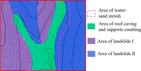
FIGURE 17. Zoning of water–sand inrush, roof caving and supports crushing, and landslide in the study area.
The disasters caused by gully mining are interrelated. Therefore, they should be analyzed systematically and comprehensively for integrated disaster prevention and control, and corresponding disaster prevention and control measures should be formulated, as shown in Figure 18. The following measures can be taken for the effective prevention and control of disasters:
(1) Water–sand inrush prevention measures: for all types of fractures, the core of prevention is to remove water and sand and close the water–sand inrush channel.
A) Interception of surface water in advance: a dam should be built in the upper reaches of Gully No. 1 and high-power pumps and drainage pipes should be used to cross the working face 113101 to transport water to the lower reaches of Gully No. 1 to maintain the natural conditions of the surface water system and the ecological balance of the surface.
B) Laying a water-resisting layer: fine sand at the bottom of Gullies No. 1 and 2 should be removed and replaced with wet loess, covered with a layer of straw, degradable plastic film, more straw, and a layer of 20 cm thick loess. To prevent surface migration from tearing the degradable plastic film, the plastic film should contain folds.
C) Choosing the time to advance: across-gully mining should be conducted during the dry season or when there is no rainfall.
D) Water storage and sand fixation: on the slope, ecological grass blanket technology or planting low shrub vegetation should be implemented for water storage, sand fixation, soil and water conservation, and ecological restoration.
(2) Gully-induced landslide prevention measures: for sliding fractures, the core prevention measures are to remove possible landslide material and reinforce rock.
A) Reduction of slope height: engineering machinery and equipment are used to remove the loess and aeolian sand on the top of the slopes of Gullies No. 1 and 2, reducing the thickness of the loose layer, overburden load, possibility of landslide, and the working face dynamic load.
B) Slope reinforcement: the lower part of the rock along the slope can be reinforced using anchors, anchor cables, slope protection nets, cement, and other equipment to prevent slope instability landslides. The reinforcement range needs to be predicted and estimated. Such reinforcement measures are often used in the construction of highways and railways in mountainous areas. The technology is mature, highly effective, and low cost.
C) Slope base grouting: grouting reinforcement is used along the slope at the base of weak weathered rock to ensure the stability of the slope base to prevent slope foundation missing landslides.
(3) Aiming prevention and control measures of roof caving and supports crushing at big intact rocks and collapse fractures: the core of prevention and control is to strengthen the weak weathered rock strata at the gully bottom, control the collapse of the roof of the goaf, and maintain the normal mine pressure law.
A) Grouting reinforcement: the root cause of roof caving and supports crushing is that the roof rock strata are small in thickness and low in strength. Therefore, grouting reinforcement at the gully bottom on the ground and underground can reduce the possibility of roof breaking.
B) Artificial cracking of the roof: the length of the suspended roof can be shortened by presplitting the middle and upper rock strata of the downhill section, easily forming a large-scale complete rock mass to collapse the roof. This reduces the possibility of advanced fractures of the roof in front of the working face. Possible splitting methods include ground drill blasting, water pressure presplitting roof, and working face roof caving. The roof failure spacing is consistent with the periodic caving step and the special area can be modified.
(4) Other prevention and control measures:
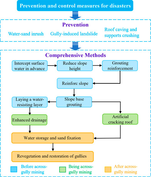
FIGURE 18. Comprehensive methods of disaster control, arranged in chronological order.
In addition to the aforementioned targeted prevention and control measures, other methods can assist in the prevention and control of various disasters, such as strengthening drainage, advancing faster with small cutting depth, reducing mining height, and moving supports with pressure. In the production process, monitoring means and prevention awareness should be strengthened. The support of the working face and roadway should be strengthened moderately. The mining scheme can be further optimized and a comprehensive command, disaster prevention, and control system can be established.
During the across-gully mining of the 113101 working face in the Kunyuan Coal Mine, the aforementioned prevention and control measures were taken. No disasters occurred during the across-gully mining task, which ensured the safety of personnel and normal production and demonstrated the reliability of these measures.
(1) Numerical simulation revealed that the macroscopic stress transfer path was as follows: the stress moved from the goaf to the surroundings in an arch shape, from the front and back of the working face to the working face, and from the top of the slope to the gully bottom. The stress state at the gully bottom transitioned from tensile stress to minor stress to compressive stress. The reverse slope section often showed a compressive state. The base of the slope often showed compressive stress, while the downhill section often showed tensile stress.
(2) Physical similarity simulation revealed the common characteristics of the dynamic development and evolution of fractures and summarized their locations. Most fractures showed the dynamic evolution from formation and expansion to development and shrinkage to healing, while fractures at the gully bottom were easy to evolve into other fractures. Collapse fractures were mostly distributed in the gully bottom, extrusion fractures were distributed in the base of the downhill section, and sliding fractures were mostly distributed in the lower part of the downhill section and reverse slope section.
(3) According to the characteristics of fracture formation and evolution, the areas and types of disasters can be predicted, and the division of disaster areas can be determined. Water–sand inrush is caused by water and sand in the gully flowing into working faces through transfixion fractures caused by mining. Roof caving and supports crushing is caused by collapse fractures in the thin bedrock of the gully bottom which cause the roof to collapse as a whole and crush the supports of working face. Gully-induced landslides are caused by mining fractures which lead to slope failure and instability or collapse at the base of a slope, forming landslides of slope instability or of base slope loss. According to the characteristics of each disaster and possible disaster areas, the disaster areas are divided into water–sand inrush areas, roof caving and support-crushing areas, and gully-induced landslide areas.
(4) For the gully bottom, we implemented measures to prevent and control water–sand inrush, such as the interception of surface water in advance and the creation of a water barrier. For the gully bottom and base of the slope of the downhill section, we implemented measures to prevent and control roof caving and supports crushing, such as grouting reinforcement and artificial roof precracking. For the middle and upper part of the downhill and uphill sections, we implemented measures to prevent and control gully-induced landslides, such as slope height reduction, slope reinforcement, and slope base grouting. These targeted prevention and control measures effectively ensured the safety of 113101 working face across-gully mining and achieved good social and economic benefits.
The raw data supporting the conclusion of this article will be made available by the authors without undue reservation.
HW: formulation of overall idea of the paper, writing—original abstract, and analysis of simulation data. BJ: numerical simulation, physical similarity simulation, data curation, and writing—original draft. JJ: picture processing and format review. YL: providing original experimental data, investigation, and language review.
This work was supported by the National Natural Science Foundation of PRC under Grant Nos. 51634007 and 51974230 and the Major Science and Technology Innovation Projects in Shandong Province under Grant No. 2019JZZY020326. The Youth Innovation Team of Shaanxi Universities.
Support from the aforementioned agencies is gratefully acknowledged.
Author YL was employed by the China Coal Technology & Engineering Group Corp.
The remaining authors declare that the research was conducted in the absence of any commercial or financial relationships that could be construed as a potential conflict of interest.
All claims expressed in this article are solely those of the authors and do not necessarily represent those of their affiliated organizations, or those of the publisher, the editors, and the reviewers. Any product that may be evaluated in this article, or claim that may be made by its manufacturer, is not guaranteed or endorsed by the publisher.
Bai, H., Mao, X., Yao, B., and Tang, J. (2009). Research on simultaneous exploitation of coal and groundwater in LU′AN coalfield. Chin. J. Rock Mech. Eng. 28, 395–402.
Che, X., Hou, E., Sun, X., Jiang, Y., Xie, X., Cong, T., et al. (2021). Research on overburden breaking characteristics and ground crack formation mechanism of shallow coal seam under the gully. J. Xi’an Univ. Sci. Technol. 41, 104–111+186. doi:10.13800/j.cnki.xakjdxxb.2021.0114
Chen, W. (2015). Study on mechanism and control technology of mining water disasters under loess gully runoff in Northern Shaanxi. [Dissertation]. Beijing, China: China University of Mining and Technology.
Chen, Y. (2020). The law of ground collapse and the prediction of water bursting risk in ZhangJiaMao Coal Mine. [Dissertation]. Xi’an, China: Xi’an University of Science and Technology. doi:10.27397/d.cnki.gxaku.2020.000695
Dong, S., Wang, H., Guo, X., and Zhou, Z. (2021). Characteristics of water hazards in China’s coal mines: a review. Mine Water Environ.40, 325–333. doi:10.1007/S10230-021-00770-6
Fang, G., and Xia, Y. (2018). Prevention and control technology of water during mining extremely thick coal seam with thin rock roof under ditch in Chaigou coal mine. J. Xi’an Univ. Sci. Technol. 38, 758–766. doi:10.13800/j.cnki.xakjdxxb.2018.0509
Gu, D., Zhang, Y., and Cao, Z. (2016). Technical progress of water resource protection and utilization by coal mining in China. J. China Coal Soc. 44, 1–7. doi:10.13199/j.cnki.cst.2016.01.001
Gu, D., Li, T., Li, J., Guo, Q., Jiang, B., Bian, W., et al. (2021). Current status and prospects of coal mine water treatment technology in China. Coal Sci. Technol. 49, 11–18. doi:10.13199/j.cnki.cst.2021.01.002
Hou, E., Chen, Y., Che, X., Xie, X., and Gao, B. (2021a). Study on overburden failure characteristics and fracture evolution law of shallow buried coal seam through trench mining. Coal Sci. Technol. 49, 185–192. doi:10.13199/j.cnki.cst.2021.10.025
Hou, E., Feng, D., Xie, X., Cong, T., Li, M., Feng, C., et al. (2021b). Development characteristics and treatment methods of mining surface cracks in shallow-buried coal seam gully. J. China Coal Soc. 46, 1297–1308. doi:10.13225/j.cnki.jccs.2020.0143
Jiang, Z., Lei, S., Cao, H., Guo, L., Zhang, J., and Qiao, X. (2017). Coal mining under river recharged by desert. J. China Coal Soc. 42, 73–79. doi:10.13225/j.cnki.jccs.2016.5030
Li, T., Gao, Y., Guo, L., and Feng, H. (2020). Prediction of water inflow with mining across ditches in loess ridge area based on runoff-confluence seepage water filling mode. J. Henan Polytech. Univ. 39, 23–27. doi:10.16186/j.cnki.1673-9787.2020.6.4
Li, J. (2013). Study on the mechanism and prevention and control technics of sand inrush and water blasting of shallow buried coal seam mining under thin bedrock. [Dissertation]. Xi’an, China: Xi’an University of Science and Technology.
Li, X. (2021). Study on evolution law and seepage characteristics of mining-induced fissure in overlying rock of shallow and thick coal seam in loess gully region. [Dissertation]. Baotou, China: Inner Mongolia University of Science and Technology. doi:10.27724/d.cnki.gnmgk.2021.000394
Lin, G., Jiang, D., Fu, J., Dong, D., Sun, W., and Li, X. (2020). Spatial relationships of water resources with energy consumption at coal mining operations in China. Mine Water Environ. 39, 407–415. doi:10.1007/s10230-020-00663-0
Liu, H. (2014). The development law and treatment technology of ground fissures due to underground mining in loess hilly area of Western China. [Dissertation]. Beijing, China: China University of Mining and Technology.
Liu, Y. (2014). The water inflow prediction methods of working face under different mining conditions of shallow coal seam. Saf. Coal Mines 45, 158–161. doi:10.13347/j.cnki.mkaq.2014.02.049
Luo, L., and Fan, K. (2015). Water prevention and treatment system of shallow buried thin bedrock seam mining along valleys. Saf. Coal Mines 46, 203–206. doi:10.13347/j.cnki.mkaq.2015.12.057
Sun, Y., Chen, G., Xu, Z., Yuan, H., Zhang, Y., Zhou, L., et al. (2020). Research progress of water environment,treatment and utilization in coal mining areas of China. J. China Coal Soc. 45, 304–316. doi:10.13225/j.cnki.jccs.YG19.1654
Wang, F., Tu, S., Zhang, C., Zhang, Y., and Bai, Q. (2016). Evolution mechanism of water-flowing zones and control technology for longwall mining in shallow coal seams beneath gully topography. Environ. Earth Sci. 75, 1309. doi:10.1007/s12665-016-6121-4
Wang, F., Ma, Q., Zhang, C., and Feng, G. (2020). Overlying strata movement and stress evolution laws triggered by fault structures in backfilling longwall face with deep depth. Geom. Nat. Hazards Risk 11 (1), 949–966. doi:10.1080/19475705.2020.1763482
Wang, S., Wei, J., Song, S., Hou, E., and Sun, T. (2022). Study on overburden and surface damage characteristics of shallow-buried coal seam mining in loess gully area. Coal Sci. Technol. 50, 1–9. doi:10.13199/j.cnki.cst.2022-0389
Wei, B., Wang, H., and Shang, H. (2022). Study on overburden failure characteristics and surface water infiltration law of coal seam mining through gully. Saf. Coal Mines 53, 161–168. doi:10.13347/j.cnki.mkaq.2022.06.026
Wei, J., Wang, S., Song, S., and Sun, Q. (2022). Numerical simulation of evolution law of overburden fractures and surface cracks in shallow coal seam through ditch mining. Coal Geol. Explor. 10, 67–75. doi:10.12363/issn.1001-1986.22.03.0134
Wu, Q., Shen, J., and Wang, Y. (2017). Mining techniques and engineering application for “Coal-Water” dual-resources mine. J. China Coal Soc. 42, 8–16. doi:10.13225/j.cnki.jccs.2016.5032
Zhang, S., Fan, G., Zhang, D., and Li, Q. (2018). Physical simulation research on evolution laws of clay aquifuge stability during slice mining. Environ. Earth Sci. 77 (7), 278–310. doi:10.1007/s12665-018-7401-y
Zhang, S., Fan, G., Zhang, D., Li, S., Chen, M., Fan, Y., et al. (2021). Impacts of longwall mining speeds on permeability of weakly cemented strata and subsurface watertable: a case study. Geom. Nat. Hazards Risk 12 (1), 3063–3088. doi:10.1080/19475705.2021.1993354
Keywords: loess gully area, shallow coal seam, coal water co-mining, characteristics and transfer of stress, fractures of overburden, prevention and control of disasters
Citation: Wang H, Jiang B, Jiao J and Li Y (2023) Overburden stress evolution characteristics and prediction of disasters with across-gully mining. Front. Earth Sci. 11:1115323. doi: 10.3389/feart.2023.1115323
Received: 03 December 2022; Accepted: 02 February 2023;
Published: 20 February 2023.
Edited by:
Fangtian Wang, China University of Mining and Technology, ChinaReviewed by:
Shizhong Zhang, China University of Mining and Technology, ChinaCopyright © 2023 Wang, Jiang, Jiao and Li. This is an open-access article distributed under the terms of the Creative Commons Attribution License (CC BY). The use, distribution or reproduction in other forums is permitted, provided the original author(s) and the copyright owner(s) are credited and that the original publication in this journal is cited, in accordance with accepted academic practice. No use, distribution or reproduction is permitted which does not comply with these terms.
*Correspondence: Baolin Jiang, amlhbmdiYW9saW5feHVzdEBmb3htYWlsLmNvbQ==
Disclaimer: All claims expressed in this article are solely those of the authors and do not necessarily represent those of their affiliated organizations, or those of the publisher, the editors and the reviewers. Any product that may be evaluated in this article or claim that may be made by its manufacturer is not guaranteed or endorsed by the publisher.
Research integrity at Frontiers
Learn more about the work of our research integrity team to safeguard the quality of each article we publish.