 Jian Meng1,2
 Kexin Yin
94% of researchers rate our articles as excellent or good
Learn more about the work of our research integrity team to safeguard the quality of each article we publish.
Find out more
ORIGINAL RESEARCH article
Front. Earth Sci., 23 March 2023
Sec. Environmental Informatics and Remote Sensing
Volume 11 - 2023 | https://doi.org/10.3389/feart.2023.1103323
This article is part of the Research TopicGroundwater-Induced Geological Disasters in Underground Engineering: Theoretical, Experimental, and Numerical ApproachesView all 12 articles
Since groundwater is one of the main factors that affect the stability of highway slopes in mountainous regions, a smooth drainage is of importance for the safety of cut slopes. After years of service, the cut slopes of highway are often characterized with drainage problems or even drainage failures that threaten the stability and safety. In this paper, the clogging mechanism of drainage holes in highway cut slopes is firstly clarified through on-site survey. The soil and blockage samples are collected from typical slopes for laboratory tests and analysis, and the results reveal that all the blockages are made of fine-grained particles from the slopes. Scanning electron microscope (SEM) images indicate that the blockages penetrate the drainage pipe wrappings to form the clogging. The combined effect of clayey soil, chemicals, and biological clogging exacerbate the clogging process around the drainage pipes. Laboratory tests are also performed to simulate the CaCO3 crystal clogging around the drainage holes, and the microstructure of the clogged geotechnical screens and geotextiles is observed by scanning electron microscope as well. The results confirm that the amount of CaCO3 crystal attached to the drainage pipe surface increases with the time. The single-layer structure of screens does not facilitate the three-dimensional clogging as in the case of geotextiles. After soaking in diluted hydrochloric acid at a pH of 5.0, there is no significant decrease of CaCO3 crystals attached on the screens and geotextiles. However, the CaCO3 decrease is apparent after soaking in the hydrochloric acid at a pH of 3.0. The clogging of drainage holes can be classified into two stages according to the laboratory tests and acid soaking, and the relationship and characteristics between the two stages are summarized.
The stability slope is a major issue for the highway engineering in mountainous area (Pantelidis, 2009; Subramanian et al., 2017; Latief and Zainal, 2019; Liu et al., 2021; Tsao et al., 2021). Since groundwater is one of the main factors that affect the deformation and stability of slopes, ensuring a smooth drainage is essential for the safety slopes (Castro et al., 2020; Nistor et al., 2020; Zhang et al., 2020; He et al., 2021). Water-rich slopes widely exist in highway engineering in South China. Due to the large annual precipitation, long rainy season, and high groundwater level, the rock-soil body of the slope is often immersed below the groundwater level for a long period. The physical, chemical, and mechanical erosion induced by the groundwater have a coupled effect on the stability of rock-soil body in the slope (Jiao et al., 2005; Wu et al., 2008). Under the long-term action of groundwater, some components in the rock-soil materials may be washed away (Gu et al., 2015). As a result, the structural plane strength that determines the stability of the rock-soil body decreases, and the stability of the slope declines finally. The hydrodynamic pressure generated by the groundwater seepage increases the sliding force of the rock-soil mass within the slope. At the same time, the buoyancy effect of the high groundwater level decreases the slipping resistance of the rock-soil mass, which in turn leads to a decrease on the stability (Santoso et al., 2011; Zhang et al., 2011; Kaczmarek and Popielski, 2019).
In addition to the regular reinforcements, drainage devices on the surface or in the deep part of the cut slopes are often installed. For instance, the upward inclined drainage holes are the most widely used method (Cahyadi et al., 2018; Hongyue et al., 2019; Sun et al., 2021). Upward inclined drainage holes are usually installed by drilling holes with a small upward inclination from the slope surface into the deep part and inserting plastic drainage pipes into the holes for draining water (Guo et al., 2018). The plastic pipes could be unperforated to allow a water drainage from the end part inside the slope or collect drainage from the perforated section. Perforated drainage pipes are specially designed to prevent clogging or failure (Cao et al., 2021), for instance, to have a geotextile wrapped around (Mininger, 2010; Guo et al., 2018). After several years’ running, cut slopes of early-built highways are often with problems of poor drainage or even drainage failures, resulting in unguaranteed stability and safety (Guo et al., 2018; Zhang et al., 2020). Therefore, studying the formation and development mechanism of the clogging in upward inclined drainage holes is of great significance for investigating new technologies to prevent or delay the clogging process, and to extend the effectiveness of drainage holes. It is also important for the stability of the cut slopes.
So far there is no literature to present detailed research on the clogging mechanism of the upward inclined drainage holes. In this paper, the slope drainage holes were investigated firstly by the on-site survey to locate the serious and typical drainage clogging sections for further study. The representative clogged drainage holes under different geological conditions were compared to determine the similarities and differences of the clogging mechanisms. The rock-soil mass, blockage soils, and water in the typical sections with clogged drainage holes were sampled and then analyzed in laboratory. Then, the chemical clogging tests were conducted with a consideration on the design and operation conditions of the upward inclined drainage holes, in order to reveal the chemical clogging mechanism and the development rules. The clogging of drainage holes can be classified into two stages according to the on-site survey, chemical clogging tests, and comprehensive analysis.
The highway section studied herein is on the Beijing-Hong Kong-Macau Expressway, starting from Xiaotang at the junction of Hunan and Guangdong and ending at Gantang in the western suburbs of Shaoguan, with a total length of 109.9 km. The section was constructed from October 1998 to April 2003. An on-site survey of this studied area shows that the expressway is in a region with complicated geology conditions. The lithology conditions are highly heterogeneous, which is mainly consist of sandstone, siltstone, and argillaceous sandstone, with locally distributed shale, carbonaceous shale, and heavily weathered coal seam. The groundwater is mianly fissure water, and water seepage and mudflow widely exist on some parts of the slope. The middle section is karst-developed limestone with high liquid limit soils overlying. The studied section is rich in groundwater, and there is an outcrop of groundwater on many slopes along the expressway. In addition, karst caves and collapses can be found in the local region, and most of the groundwater is fissure water or karst water. The frequent landslides and other undesirable geological hazards are common to encounter such as debris flow or collapse in the research area, which pose high potential risks to the stability of the slopes and the serviceability of the highway.
The slopes studied in the paper are characterized with poor drainage or drainage failure, and the old drainage holes have worked more than 10 years (see Figure 1). Most of the clogged drainage holes are blocked with fine-grained soil, and chemical crystallization can be found in the blockages. Most of the drainage holes show traces of algae and other organisms on the surface. Preliminary analysis during the on-site survey shows that the main reasons for the clogging and drainage failure of the upward inclined holes are summarized as follows.
1) The composition of the rock-soil mass varies greatly, and the transfer of particles and chemical crystals within the slope can easily induce mechanical or chemical clogging in the drainage holes and on the geotextile.
2) There are obvious seasonal variations in the groundwater level of the slope. The upward inclined drainage holes work intermittently, i.e., only in rainy seasons or non-rainy seasons with sudden heavy rainfall. Thus, the geotextile is exposed to the atmosphere for a long period of time. Biological activities and variations in the redox environment can easily cause chemical and biological clogging on the geotextile. The mutual effect between physical, chemical, and biological clogging eventually accelerates the clogging process of the drainage holes.
3) Since the geotextile wrapped around the drainage pipes cannot be cleaned or replaced after the installation, the clogging continues until the drainage holes fail to work. In this way, the geotextile wrapped cannot prevent the clogging in the long time of running.
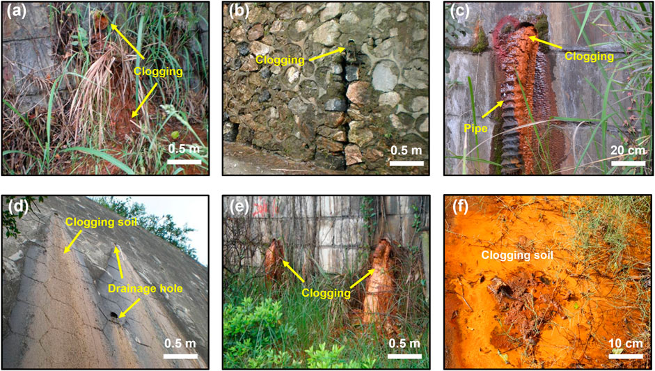
FIGURE 1. Inclined drainage holes with poor drainage and clogging problem: (A) red clogging soil with plants; (B) brown clogging soil; (C) soft drainage pipe with red clogging soil; (D) clogging materials after rainfall; (E) totally clogging drainage holes; (F) red clogging soil near the drainage holes
Most of the drainage holes in the research area are characterized by different degrees of clogging, and nine typical slope sections with serious drainage clogging were selected for further research. The drainage clogging in the selected slopes distributed in the three typical geological sections was statistically analyzed. As shown in Table 1, the slopes in all three sections show serious clogging problem. Cracks appear on the slopes, and groundwater seeps out through these cracks due to the failed drainage holes. The cracks and groundwater seepage decrease the stability of the slopes.
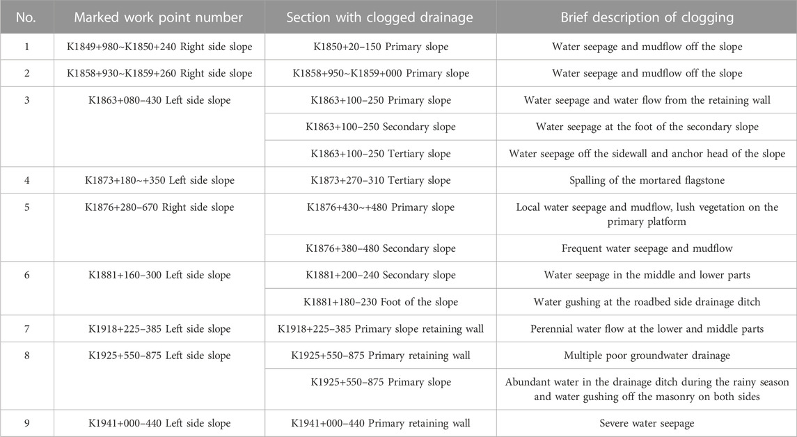
TABLE 1. Cut slopes with clogged drainage.
Based on the analysis on the long-time running drainage holes, most of the serious clogging occurred after about 3 years of working. The average clogging time is 3.2 years according to a standard that the holes cannot drain water after a rainfall (see Table 2). New drainage holes are constructed on the clogging zone for later study and the stability of the slopes.
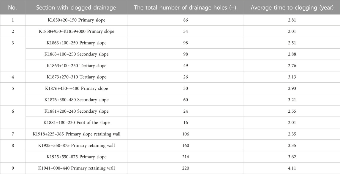
TABLE 2. The information of the clogged drainage holes.
To analyze the typical clogging, three soil and three water samples were collected from each typical slope with clogged drainage holes for laboratory tests. The inner pipes were extracted from the representative clogged drainage holes, and the blockage materials in the clogged drainage holes were also sampled for laboratory tests and analysis.
Soil samples of the three typical slopes and their drainage hole blockages were collected for granulometric analysis. The particle size distribution curves were then obtained. Three slope soil samples and three drainage hole blockage samples were collected from each typical slope for testing, and the average values of every three samples were adopted for further analysis. The particle diameter of the slope soil varies greatly, while the blockages mostly consist of fine particles. Thus, both the sieving and densitometer methods were used to analyze the particle size distribution of the soil particles. As shown in Figure 2, the particle distribution curves from the average data of the three typical slope soil samples and the corresponding drainage hole blockages are compared: i.e., the right-side slope of K1858+930∼K1859+260, the right-side slope of K1876+280–670, and the left-side slope of K1925+550–875 are presented here. The mark number K1858+930∼K1859+260, K1876+280–670, and K1925+550–875 are renamed hereafter as K1858, K1876, and K1925, respectively.
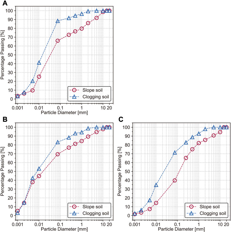
FIGURE 2. The particle size distribution of the three selected slope soil samples and their corresponding drainage hole blockages: (A) section K1858+930∼K1859+260; (B) section K1876+280–670; (C) section K1925+550–875.
According to the results from the above tests, the particle composition of the soil samples and drainage blockages of the three selected slopes is as follows.
1) The right-side slope of section K1858 is made of silty clay with grain size distribution shown in Figure 2A, in which the average soil content with a diameter below 0.075 mm is 66.0%. The drainage hole blockages are mainly clay, and the content of soils with a diameter below 0.075 mm is 88.4% (Figure 2A).
2) The right-side slope of section K1876 is made of clay with grain size distribution shown in Figure 2B, in which the average content of particles below 0.075 mm is 69.5%. The drainage hole blockages are fine-grained soil (Figure 2B) with a diameter lower than 2 mm, of which the total content of particles below 0.075 mm is 83.2%.
3) The soil sample from the left slope of section K1925 is silt, mainly composed of sand and clay, and the content of soil particles below 0.075 mm is 39.8% (Figure 2C). The drainage hole blockages are mainly silt and clay, and the content of particles below 0.075 mm is 71.4% (Figure 2C).
Except for the left slope of the section K1925, the fine particle content in the soil of the other two slopes with clogged drainage holes is high, and the content of fine particles below 0.075 mm is above 65%. Although the fine particle content of the left slope of section K1925 is 26.2%–29.7% lower than the other two slopes (K1858 and K1876), the corresponding drainage hole blockages of all the three slopes are mainly fine-grained soil at high contents (71.4%–77.4%). The fine particle content in the drainage hole blockages is larger than that of the slope soil. Therefore, the drainage blockages are formed due to the fine particles from the side slope soil that are transported and accumulated by groundwater.
Comparative compositional analysis of the slope soil and blockage samples was performed using X-ray fluorescence (XRF), which was simple to operate, non-destructive, fast, and accurate (Dos Anjos et al., 2000; Silva et al., 2019; Ravansari et al., 2020). Compositions of the three typical slope soil samples and drainage hole blockages are shown in Table 3 and Table 4, respectively.
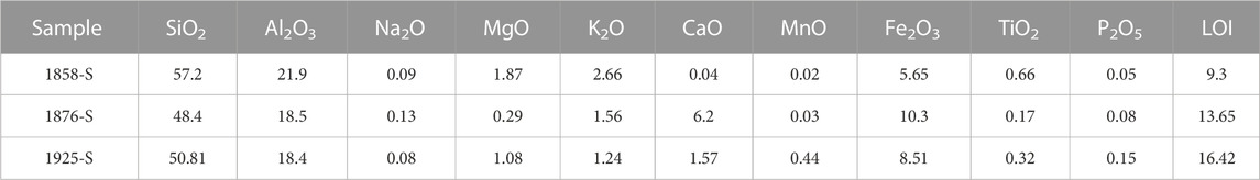
TABLE 3. Slope soil composition.
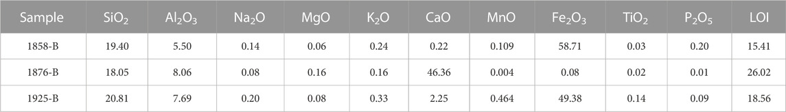
TABLE 4. Blockage composition.
According to the on-site survey, the drainage holes of section K1858 are located in a pelitic sandstone section, those of section K1876 in the limestone section, and those of K1925 in the interbedded strata of shale, mudstone, and sandstone. A comparison of the compositions of soil samples from the three slopes and their drainage hole blockages indicates that.
1) The composition of the drainage hole blockages in the three selected sections is the same as the slope soil, mainly silicon and aluminum oxides. Therefore, the clay content in the drainage hole blockages is high. Clay can promote mechanical clogging in the drainage hole. The fine-grained soil is the main material for mechanical clogging of drainage holes, which is also consistent with the results of particle distribution tests.
2) The calcium oxide content of the blockages in the limestone section K1876 is significantly higher than that in the corresponding slope soil, which may be attributed to the calcium precipitation around the drainage hole with intermittent groundwater outflow, i.e., the chemical clogging. At the same time, an analysis on the clogging materials in the newly running drainage holes finding that there is nearly no increase on the CaCO3 crystals, indicating that the chemical clogging is developing in a low rate.
3) The iron oxide content of blockages in sections K1858 and K1925 is significantly higher than that in the slope. Therefore, Fourier Transform Infrared Spectroscopy (FTIR) analysis of the samples is necessary to determine the iron composition (Hahn et al., 2018).
FTIR analysis on the blockage samples from sections K1858 and K1925 shows that the Fe in the blockage from section K1858 is possibly a mixture of Fe(OH)3 and α-Fe2O3•H2O. While the Fe in samples from K1925 is possibly Fe(OH)3. On-site analysis of the water quality shows that the contents of free CO2, erosive CO2, and total dissolved solids are 50.18 mg/L, 34.17 mg/L, and 547.08 mg/L, respectively, making it moderately corrosive (pH = 4.5). The wire skeleton of flexible drainage pipes is generally corroded, and the same high Fe content is not detected in the blockages without flexible drainage pipes. Therefore, most of the Fe in the blockage comes from the wire skeleton of the flexible drainage pipes (Figure 1C), which is consistent with the conclusion that the ferrous blockage is mainly iron hydroxide and its transformations as indicated in the literature (Wu et al., 2007; Wu et al., 2008). Therefore, flexible drainage pipes have poor suitability for the research slope area.
A large number of calcium oxides is found in the blockages of the limestone section K1876. Water samples were collected from the slopes in this section for quality analysis to identify the chemical clogging mechanism of the drainage holes. The water quality analysis results of the slopes in the limestone section K1876 are shown in Table 5. The results show that all the groundwater within the slopes is SO42--Ca2+-Mg2+ water, mostly neutral or alkaline water. However, the contents of SO42-, Ca2+, and Mg2+ vary significantly in the sampling places.
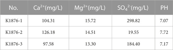
TABLE 5. Water quality analysis.
Scanning electron microscope (SEM) is an effective method to investigate the microstructure of soils (Yin et al., 2019; Yin et al., 2021a; Yin et al., 2021b; Yin et al., 2021c; Yin, 2021). In order to further study the microstructure of the clogged drainage holes, SEM scans were performed on the inner and outer surfaces of the clogged drainage pipes at both ends (i.e., the outer and the inner pipe end). The images of the inner surface of the clogged drainage pipes are shown in Figures 3A, B, and the outer surface images are presented in Figures 3C, D. The SEM results show significant differences between the blockages on the inside and outside surfaces of the outer section of the drainage pipes. The fiber on the inner surface is still clearly visible, while that on the outer surface is completely covered by the blockage. Therefore, the blockage materials gradually penetrate from the outer surface of the drainage pipes to the inner surface, and eventually reach saturation on the whole fiber. Thus, blockage materials are prevented from entering the interior and accumulating and just adhering to the outer surface of the drainage pipes.
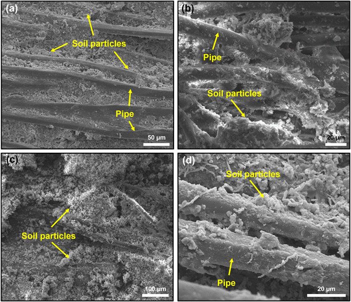
FIGURE 3. SEM images at the outer pipe end: (A), (B) inner surface; (C), (D) outer surface.
Scanning images of the inner and outer surfaces of the inner pipe end are collected in Figure 4. Similar to the scans of the outer ends, at the inner end, fibers are visible on the inner surface but not on the outer surface. SEM images indicate more blockage at the inner end than the outer end of the drainage pipe (see Figure 3 and Figure 4). Therefore, the clogging of the drainage pipe at the inner pipe end is more severe than that at the outer end.
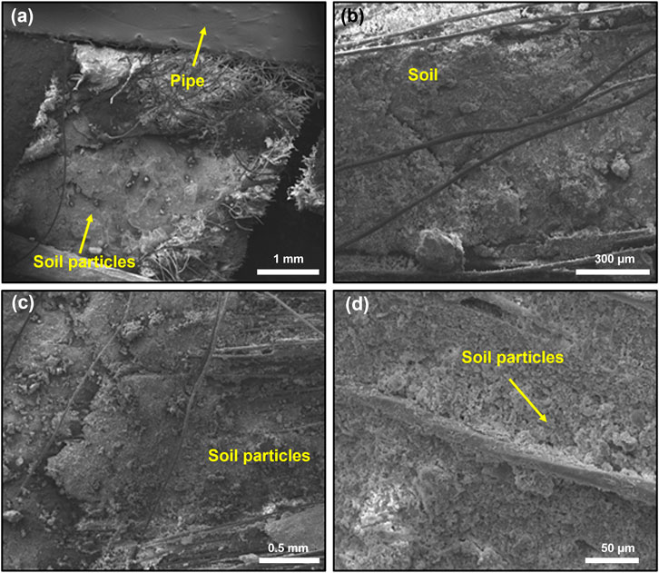
FIGURE 4. SEM images of the inner pipe end: (A), (B) inner surface; (C), (D) outer surface.
From the SEM images, we can see that the clogging develops from the materials wrapped (geotextile and screen). The fine particles transferred by the underground water accumulate on the wrapped geotextile and screen. More clogging is formed in the bottom of the drainage holes due to the transportation effect of the underground water.
Since most of the drainage holes work for a short time throughout the year, chemical clogging is often neglected. Few studies focused on the chemical clogging in the side slopes, especially in limestone regions (Luquot et al., 2014). The above analysis on the clogging materials provide proofs for that chemical clogging in limestone regions is mainly in the form of CaCO3. Hence, it is necessary to perform model tests in the laboratory, to investigate the CaCO3 chemical clogging mechanism as well as to know the distribution, arrangement and microstructure of the CaCO3 crystal. Experiments of chemical clogging with different materials can offer useful information on drainage hole clogging improvements and delay or prevention of the chemical clogging.
Under the action of water and CO2, the abundant calcium ions in the groundwater undergo chemical dissolution, and the reaction equation is as follows:
Ca(HCO3)2 has a much higher solubility than CaCO3. With abundant groundwater and CO2, the water discharge from the side slope drainage holes generally contains more Ca(HCO3)2. However, the highly unstable Ca(HCO3)2 can be reduced to CaCO3 precipitation under decreased pressure or increased temperature, which can easily block the drainage holes due to their mutual adhesion. In order to simulate the effects of calcium precipitates on the clogging process and the clogging degree in the drainage holes (especially the outer wrapping of drainage pipes) of cut slopes, the highly soluble CaCl2 solution was selected to provide Ca2+, and NaHCO3 solution was used to promote Ca2+ in generating Ca(HCO3)2 precipitation. Then, a certain amount of Ca(HO)2 was added to induce the conversion of Ca(HCO3)2 into the more stable CaCO3. The chemical formulas for the above reactions are as follows.
The above process was applied to the geotechnical screen and geotextile wrapped around the drainage pipes to simulate the calcareous blockage process. The geotechnical screen and geotextile were saved and sampled in steps, and SEM scanning was performed to analyze the form and extent of clogging. Diluted acid was used to clean the screen and geotextile with chemical blockage, and the cleaning effect was observed as well. The reaction between the diluted acid and CaCO3 is as follows:
Several containers were needed to hold various chemical reagents for the experiment. Synthetic fiber screens (200 mesh) and geotextiles of different sizes were cut into 5.0 cm × 5.0 cm for the experiment. The CaCO3 crystallization adhered to the screens and geotextiles needed to be titrated with different acids and then compared. After the experiment, the screen and geotextile will be sampled for SEM scanning, which aims to reveal the internal microstructure and clarify the chemical clogging mechanism in the drainage holes and pipes. In addition, CaCl2, Ca(HO)2, Ca(HCO3)2, and HCl solutions of the required concentrations were prepared according to the experimental needs.
The detailed steps of the experiment are described as follows.
1) A 0.05 mol/L CaCl2 solution, a 0.50 mol/L NaHCO3 solution, a saturated Ca(OH)2 solution, and HCl solutions at pH of 3, 4, and five were prepared with distilled water.
2) The screen and geotextile were soaked in the 0.50 mol/L NaHCO3 solution and then titrated with 0.05 mol/L CaCl2 solution, followed by Ca(OH)2 solution. The screen and geotextile were dried after the reaction and then gently washed with distilled water to remove the soluble materials before being dried again. Two pieces of the screen and geotextile squares were sealed and stored: one for SEM scanning tests and the other for titration with a diluted acid. The rest of the screen and geotextile were used for subsequent experiments.
3) The dried screen and geotextile in Step 2 were titrated with the 0.50 mol/L NaHCO3 solution until saturation and then titrated with the 0.05 mol/L CaCl2 solution and Ca(OH)2 solution. The screen and geotextile were dried after the reaction and washed with distilled water to remove the soluble materials before being dried again. One of the screens and geotextiles was sealed and kept for SEM scanning, and the rest were used for subsequent experiments.
4) Step 3 was repeated until all screens and geotextiles were tested.
5) The screens and geotextiles in the above procedures saved for titration with diluted acid were subjected to diluted acid titration. Specifically, screens and geotextiles that underwent one precipitation test were titrated once, and those that underwent multiple precipitation tests were titrated an equal number of times to their number of precipitation. The phenomena that occurred during the test were observed, and the amount of diluted acid consumed was recorded. Then, the screens and geotextiles were dried and saved for SEM scanning.
6) Saturated CaCl2, NaHCO3, and Ca(OH)2 solutions were prepared at room temperature that is consistent with the in situ temperature, due to the changes of temperature will have impact on the chemical reactions (i.e., the higher temperature the faster reaction). Two screens and two geotextiles were soaked in NaHCO3 solutions and then titrated with saturated CaCl2 and Ca(OH)2 solutions until the reaction was completed. The screens and geotextiles were dried and then washed with distilled water to remove the soluble materials before being dried again. One piece was saved for SEM scanning, and the other was titrated with diluted acid until the reaction was completed. The experimental phenomena were recorded.
7) All tested screens and geotextiles were subjected to the SEM scanning tests.
The screen and geotextile after the first two steps in Section 3 were scanned by SEM to observe the attachment of CaCO3 crystals. Both the screen and the geotextile have CaCO3 crystals attached to the fiber surface (see Figure 5). Under the in situ condition, as the working time of the drainage holes goes on, precipitated CaCO3 crystals are accumulating on the screen and geotextile due to their high cohesiveness, thus exacerbating the clogging. From the distribution of the chemical clogging, it can be concluded that the wrapped materials with single-layer structure and larger pore size is more effective than these with multi-layer structure and smaller pore size to prevent the clogging.

FIGURE 5. The attachment of CaCO3 crystals on: (A) screen; (B) geotextile.
The CaCO3 crystal precipitation around the drainage holes with increasing in situ operation time was simulated by varying the number of CaCl2 and Ca(OH)2 titration. The images of the screens and geotextiles after titration are shown in Figure 6. A comparison of the microstructure of CaCO3 precipitation indicates that the CaCO3 crystals attached to the surface of the screen and the geotextile fibers increase with the increasing number of titrations. The CaCO3 crystals continuously attach to and accumulate on the fibers, leading to blockage. With time going on, the crystal precipitation increases, and then chemical clogging intensifies.
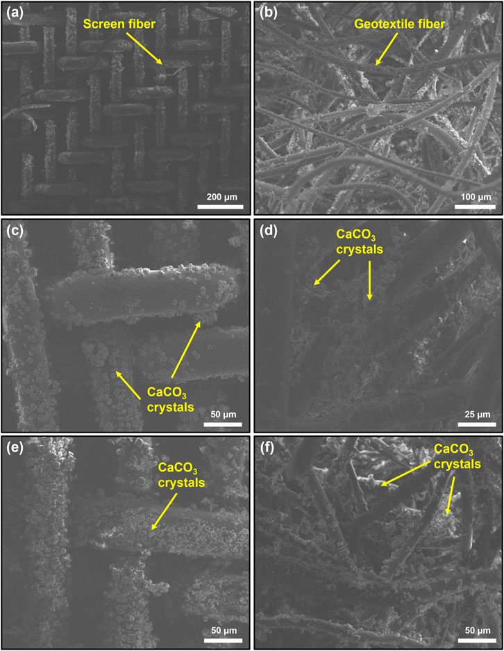
FIGURE 6. The screens and geotextiles under different titrations: (A), (B): 3 titrations; (C), (D): 6 titrations; (E), (F): 9 titrations.
The screens and geotextiles attached with CaCO3 crystals were soaked in a diluted hydrochloric acid at a pH of 5.0 for 5 min, to observe the cleaning effect of acid washing on the chemical blockages. As presented in Figure 7, the decrease of CaCO3 crystals attached to the screen and geotextile fibers was not significant after the acid washing with a pH = 5.0.
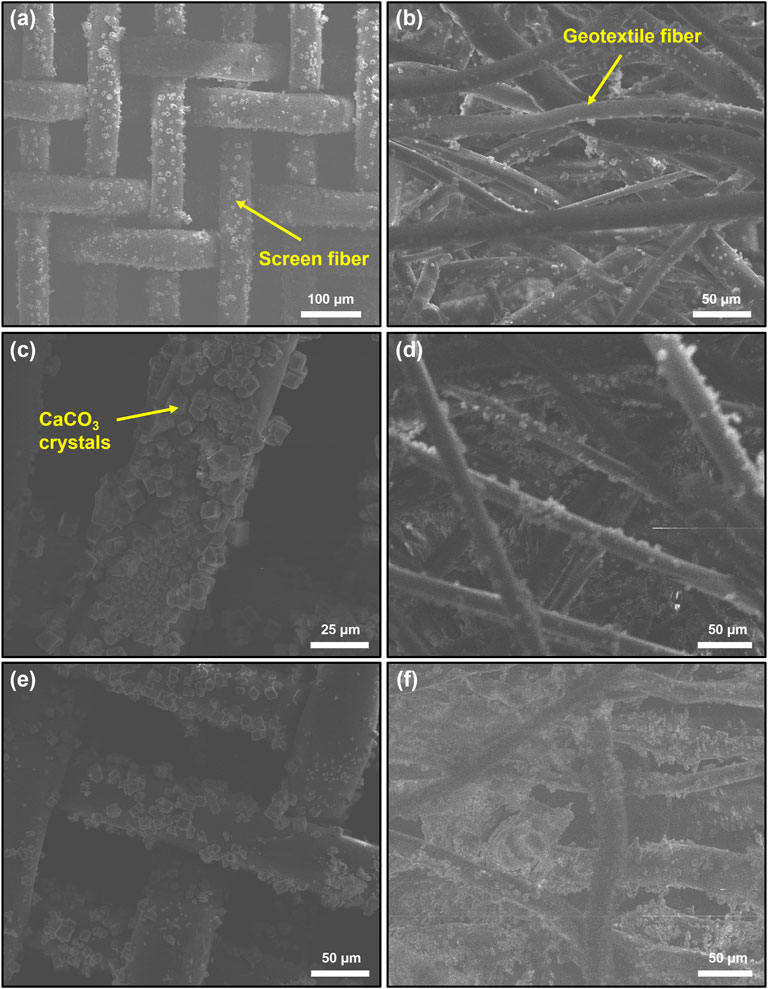
FIGURE 7. SEM images of the screens and geotextiles after: (A), (B): 3 titrations of acid washing; (C), (D): 6 titrations of acid washing; (E), (F): 9 titrations of acid washing.
Since the decrease in the attached CaCO3 crystals is not so significant after soaking in acid at the pH of 5.0, stronger hydrochloric acids are employed. SEM images of the screen and geotextile soaked with hydrochloric acid at a pH of 3.0 after 6 titrations are shown in Figure 8. The decrease in CaCO3 crystals attached to the fibers is more significant after soaking in the stronger hydrochloric acid (pH = 3.0) for the same time (i.e., 5 min). Therefore, acid washing is effective for the Fe chemical blockage and Ca blockage.
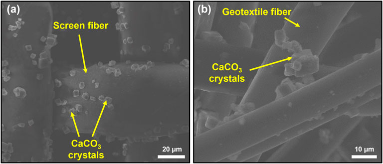
FIGURE 8. SEM images of the (A) screens and (B) geotextiles after 6 titrations of acid washing.
The clogged drainage holes in the study area were washed from the outside to the inside with high-pressure water at a pressure of about 0.1 MPa (see Figure 9). After the washing, the cleaning effects on the old and new constructed drainage holes were counted and compared separately. The recovery of drainage after a rain is taken as the judging standard for the success of hole washing. The statistical success of hole washing is shown in Table 6. The data in brackets in the table is the number of drainage holes successfully washed. The operation time of the old drainage holes in this site is more than 10 years, and now it is in the late clogging stage, while the operation of the new drainage hole is working only for 2–3 years, i.e., the initial clogging stage. It can be seen from the statistical data that the drainage holes in the initial clogging stage are mainly physical blockage, and the success rate of washing reaches 47.3%. There are blockage bonded together in the drainage holes located in the late clogging stage, due to the coupled effect of chemical and biological blockages. The Late clogging stage shows the characteristics of the three-dimensional comprehensive blockage. Therefore, the drainage effect of hole washing is not so effective, with a lower success rate of 18.6%.
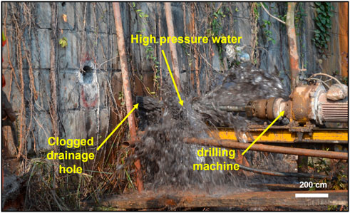
FIGURE 9. Drainage holes washing.
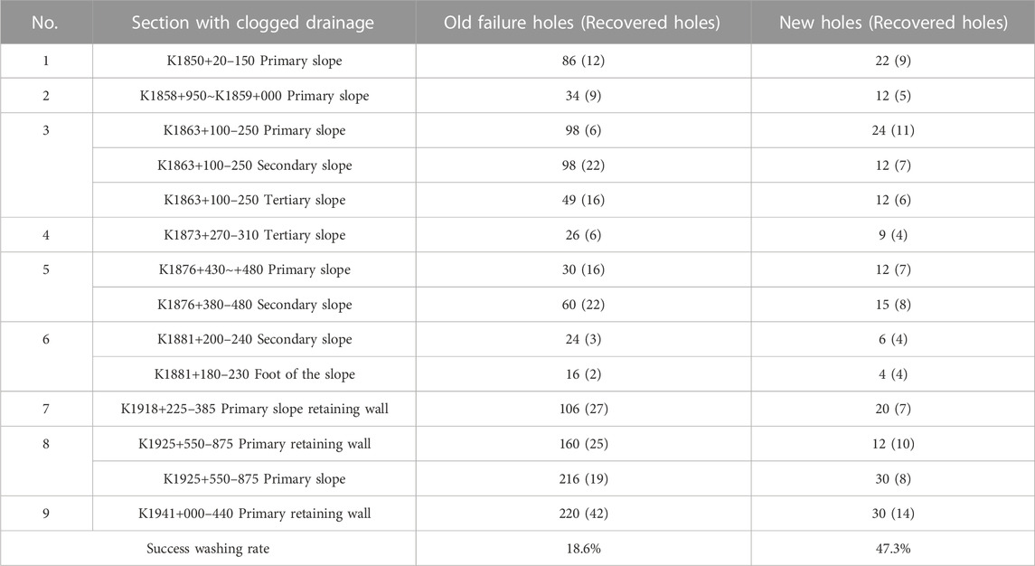
TABLE 6. Statistics of the drainage holes washing.
In this paper, the degree and mechanism of drainage hole clogging in highway cut slopes were preliminarily clarified through an on-site survey. The soil and blockage samples from the selected slopes were collected for laboratory tests and analysis. The conclusions are summarized as follows.
1) All drainage holes in the research sections are characterized by different degrees of clogging. The blockages are correlated with the slope stratum lithology, the soil particle size, and the groundwater. All the blockages are made of fine-grained particles, and the clogging of slope drainage holes in slopes with clayey soil and other fine-grained soil is usually more severe. Slope drainage holes with flexible drainage pipes are also generally clogged with the hindered groundwater discharged, indicating its poor suitability for the slopes. The blockages contain abundant iron oxides, which are found to be related to the oxidation of the steel wire skeleton inside the flexible drainage pipes by FTIR analysis.
2) SEM images show more blockages at the inner end of the drainage pipes than at the outer end and more blockages on the outside than on the inside of the drainage pipes, in agreement with the movement of underground water and the fine particles. The blockages penetrate deep inside the drainage pipe wrappings, and the combined effect of clayey soil, chemical clogging, and biological clogging exacerbate the clogging of drainage pipes with the increase in time.
3) In addition to the same oxides as that in the side slopes, the blockages in the research area also have a high content of calcium oxides, indicating chemical clogging of calcium precipitates.
The chemical clogging in the research area is mainly in the form of CaCO3 crystals attached to the outer surface of the wrapping fibers, which exacerbates the clogging with its continuous accumulation. As a commonly used wrapping material for drainage pipes, the pore size of nylon screens is larger than that of geotextile. The single-layer structure of screens does not facilitate three-dimensional clogging without crystals attached to the interior. In contrast, geotextiles facilitate three-dimensional clogging with crystals attached to the different fibers. The three-dimensional clogging is difficult to clean through traditional washing methods. Therefore, under the same conditions, the chemical clogging of screens needs more time to form and is easier to clean than the chemical clogging of geotextiles.
4) Indoor tests were also conducted to simulate the CaCO3 crystal precipitation clogging around the drainage holes in the research area, and the microstructure of the clogged screens and geotextiles was observed by using SEM. The main conclusions are in following: All chemical clogging on the screens and geotextiles is in the form of CaCO3 crystal attachment and accumulation on the fiber surface, leading to severe clogging. The higher the number of titrations on the screens and geotextiles, the more CaCO3 crystals is attached to the fiber surface. This study verifies that the amount of CaCO3 crystals attached to the surface of the wrapping outside the drainage pipes increases with the operation time. Therefore, the effect of chemical clogging should be considered for the long-term operation of drainage holes. The decrease in CaCO3 crystals attached to the screens and geotextiles is not significant after soaking in diluted hydrochloric acid at the pH of 5.0 but significant after soaking in hydrochloric acid at the pH of 3.0. Therefore, stronger acids perform better in removing part of the calcium clogging and delaying the chemical clogging. Considering the protection of environment, the acid washing method is not suggested to apply in the in situ engineering. The single-layer structure of screens does not facilitate three-dimensional clogging like in the geotextiles. In the meantime, the pore size of screens is larger than that of geotextiles. Therefore, chemical clogging on screens needs more time to form and is easier to clean than that in the geotextiles.
5) It can be seen from this study that drainage holes clogging can be divided into two typical stages: the initial stageand the late stage. The initial stage is dominated by physical blockage, which is manifested as fine grained soil that forming blockage around the drainage holes along with the groundwater migration. The physical blockage induced by fine grained soil is also a major component of the blockage. This stage is generally formed in an operation period of 2–3 years, and the drainage holes are often completely undrained. But there is usually a better hole washing effect on the drainage holes at this stage. With the increase of the operation time, the drainage holes are intermittently drained or even not drained, chemical and biological clogging become more obvious. The drainage holes located in the late stage make the blockage bond together to form a better whole because of chemical and biological blockage. Fine grained soil becomes difficult to destroy after bonding with chemicals, so the success rate of drainage hole washing at this stage is very low.
6) The structure of the drainage hole makes the clogging inevitable, to make the permanent drainage effect better, it is necessary to invent a drainage hole that is less easily clogged or better washed. The existing drainage hole blockage is based on the drainage hole wrapping material, so improving the wrapping material or even cancelling the wrapping material will be an effective direction to reduce the drainage hole blockage or make the drainage hole easier to wash.
The raw data supporting the conclusion of this article will be made available by the authors, without undue reservation.
JM, conceptualization, methodology, writing—original draft preparation, formal analysis; AC, conceptualization and methodology; KY, formal analysis, writing-original draft preparation, writing—review and editing; CZ, writing—review and editing. All authors have read and agreed to the published version of the manuscript.
This research is supported by the Talent Cultivation Project at Kunming University of Science and Technology (KKZ3201621012).
Author JM was employed by the Company Kunming Prospecting Design Institute of China Nonferrous Metals Industry Co., Ltd. Author CZ was employed by Yunnan Geological Exploration and Development Corporation.
The remaining authors declare that the research was conducted in the absence of any commercial or financial relationships that could be construed as a potential conflict of interest.
All claims expressed in this article are solely those of the authors and do not necessarily represent those of their affiliated organizations, or those of the publisher, the editors and the reviewers. Any product that may be evaluated in this article, or claim that may be made by its manufacturer, is not guaranteed or endorsed by the publisher.
Cahyadi, T., Widodo, L., Fajar, R., and Baiquni, A. (2018). “Influence of drain hole inclination on drainage effectiveness of coal open pit mine slope,” in IOP conference series: Earth and environmental science (IOP Publishing), 012060.
Cao, Y., Xu, M., Ni, P., and Mei, G. (2021). Physical and numerical modelling of infiltration from drainage holes for perforated storm sewer. Acta Geotech. 17, 527–543. doi:10.1007/s11440-021-01247-0
Castro, J., Asta, M. P., Galve, J. P., and Azañón, J. M. (2020). Formation of clay-rich layers at the slip surface of slope instabilities: The role of groundwater. Water 12 (9), 2639. doi:10.3390/w12092639
Dos Anjos, M., Lopes, R., De Jesus, E., Assis, J., Cesareo, R., and Barradas, C. (2000). Quantitative analysis of metals in soil using X-ray fluorescence. Spectrochim. Acta Part B At. Spectrosc. 55 (7), 1189–1194. doi:10.1016/s0584-8547(00)00165-8
Guo, Y., Leng, W., Nie, R., Zhao, C., and Zhang, X. (2018). Laboratory evaluation of a new device for water drainage in roadside slope along railway systems. Geotext. Geomembranes 46 (6), 897–903. doi:10.1016/j.geotexmem.2018.08.005
Gu, T. F., Zhu, L. F., Hu, W., Wang, J. D., and Liu, Y. M. (2015). Effect on slope stability due to groundwater rising caused by irrigation: a case study of Heifang Platform in Gansu. China. Geosci. 29 (2), 408–413 (in Chinese).
Hahn, A., Vogel, H., Andó, S., Garzanti, E., Kuhn, G., Lantzsch, H., et al. (2018). Using Fourier transform infrared spectroscopy to determine mineral phases in sediments. Sediment. Geol. 375, 27–35. doi:10.1016/j.sedgeo.2018.03.010
He, Y., Sun, R., Xu, Z., and Tang, W. (2021). The dynamic change and effect of rainfall induced groundwater flow. Water 13 (19), 2625. doi:10.3390/w13192625
Hongyue, S., Feixiang, S., Yuequan, S., Huan, X., and Dongfei, W. (2019). Study on negative pressure drainage method of downdip bolehole in slope. J. Eng. Geol. 27 (3), 585–591.
Jiao, J. J., Wang, X. S., and Nandy, S. (2005). Confined groundwater zone and slope instability in weathered igneous rocks in Hong Kong. Eng. Geol. 80 (1-2), 71–92. doi:10.1016/j.enggeo.2005.04.002
Kaczmarek, Ł. D., and Popielski, P. (2019). Selected components of geological structures and numerical modelling of slope stability. Open Geosci. 11 (1), 208–218. doi:10.1515/geo-2019-0017
Latief, R. H., and Zainal, A. K. E. (2019). Effects of water table level on slope stability and construction cost of highway embankment. Eng. J. 23 (5), 1–12. doi:10.4186/ej.2019.23.5.1
Liu, Z., Liu, P., Zhou, C., and Zhang, L. (2021). A theoretical framework for optimization of three-dimensional slope stability monitoring. Eng. Geol. 295, 106436. doi:10.1016/j.enggeo.2021.106436
Luquot, L., Roetting, T. S., and Carrera, J. (2014). Characterization of flow parameters and evidence of pore clogging during limestone dissolution experiments. Water Resour. Res. 50 (8), 6305–6321. doi:10.1002/2013wr015193
Mininger, K. T. (2010). Lifespan of horizontal wick drains used for landslide drainage. Colorado School of Mines.
Nistor, M. M., Rahardjo, H., Satyanaga, A., Hao, K. Z., Xiaosheng, Q., and Sham, A. W. L. (2020). Investigation of groundwater table distribution using borehole piezometer data interpolation: Case study of Singapore. Eng. Geol. 271, 105590. doi:10.1016/j.enggeo.2020.105590
Pantelidis, L. (2009). Rock slope stability assessment through rock mass classification systems. Int. J. Rock Mech. Min. Sci. 46 (2), 315–325. doi:10.1016/j.ijrmms.2008.06.003
Ravansari, R., Wilson, S. C., and Tighe, M. (2020). Portable X-ray fluorescence for environmental assessment of soils: Not just a point and shoot method. Environ. Int. 134, 105250. doi:10.1016/j.envint.2019.105250
Santoso, A. M., Phoon, K. K., and Quek, S. T. (2011). Effects of soil spatial variability on rainfall-induced landslides. Comput. Struct. 89 (11-12), 893–900. doi:10.1016/j.compstruc.2011.02.016
Silva, E. A., Weindorf, D. C., Silva, S. H., Ribeiro, B. T., Poggere, G. C., Carvalho, T. S., et al. (2019). Advances in tropical soil characterization via portable X-ray fluorescence spectrometry. Pedosphere 29 (4), 468–482. doi:10.1016/s1002-0160(19)60815-5
Subramanian, S. S., Ishikawa, T., and Tokoro, T. (2017). Stability assessment approach for soil slopes in seasonal cold regions. Eng. Geol. 221, 154–169. doi:10.1016/j.enggeo.2017.03.008
Sun, H. Y., Ge, Q., Yu, Y., Shuai, F. X., and Lü, C. C. (2021). A new self-starting drainage method for slope stabilization and its application. Bull. Eng. Geol. Environ. 80 (1), 251–265. doi:10.1007/s10064-020-01918-4
Tsao, M. C., Lo, W., Chen, W. L., and Wang, T. T. (2021). Landslide-related maintenance issues around mountain road in dasha river section of central cross island highway, taiwan. Bull. Eng. Geol. Environ. 80 (2), 813–834. doi:10.1007/s10064-020-01967-9
Wu, J., Wu, Y., and Lu, J. (2008). Laboratory study of the clogging process and factors affecting clogging in a tailings dam. Environ. Geol. 54 (5), 1067–1074. doi:10.1007/s00254-007-0873-9
Wu, J., Wu, Y., Lu, J., and Lee, L. (2007). Field investigations and laboratory simulation of clogging in Lixi tailings dam of Jinduicheng, China. Environ. Geol. 53 (2), 387–397. doi:10.1007/s00254-007-0654-5
Yin, K., Fauchille, A. L., Di Filippo, E., Kotronis, P., and Sciarra, G. (2021a). A review of sand–clay mixture and soil–structure interface direct shear test. Geotechnics 1 (2), 260–306. doi:10.3390/geotechnics1020014
Yin, K., Fauchille, A. L., Di Filippo, E., Othmani, K., Branchu, S., Sciarra, G., et al. (2021b). The influence of mixing orders on the microstructure of artificially prepared sand-clay mixtures. Adv. Mater. Sci. Eng. 2021, 1–15. doi:10.1155/2021/8552224
Yin, K., Fauchille, A. L., Othmani, K., Sciarra, G., Kotronis, P., Benoit, Y., et al. (2019). “Influence of sample preparation on the multi scale structure of sand-clay mixtures,” in E3S Web of conferences (EDP Sciences), 01007.
Yin, K. (2021). Influence of clay fraction on the mechanical behavior of a soil-concrete interface. Nantes, France: Thesis. École centrale de Nantes.
Yin, K., Liu, J., Lin, J., Vasilescu, A. R., Othmani, K., and Di Filippo, E. (2021c). Interface direct shear tests on JEZ-1 mars regolith simulant. Appl. Sci. 11 (15), 7052. doi:10.3390/app11157052
Zhang, L., Zhang, J., Zhang, L., and Tang, W. H. (2011). Stability analysis of rainfall-induced slope failure: A review. Proc. Institution Civ. Engineers-Geotechnical Eng. 164 (5), 299–316. doi:10.1680/geng.2011.164.5.299
Keywords: highway cut slope, underground water, drainage hole, clogging mechanism, CaCO3 crystal, microstructure
Citation: Meng J, Chen A, Yin K and Zhou C (2023) Study on the clogging mechanism of upward inclined drainage holes in cut slopes. Front. Earth Sci. 11:1103323. doi: 10.3389/feart.2023.1103323
Received: 20 November 2022; Accepted: 13 March 2023;
Published: 23 March 2023.
Edited by:
Liang Chen, China University of Mining and Technology, ChinaCopyright © 2023 Meng, Chen, Yin and Zhou. This is an open-access article distributed under the terms of the Creative Commons Attribution License (CC BY). The use, distribution or reproduction in other forums is permitted, provided the original author(s) and the copyright owner(s) are credited and that the original publication in this journal is cited, in accordance with accepted academic practice. No use, distribution or reproduction is permitted which does not comply with these terms.
*Correspondence: An Chen, MjAxNDAwMjVAa3VzdC5lZHUuY24=; Kexin Yin, a2V4aW4ueWluQG51YWEuZWR1LmNu
Disclaimer: All claims expressed in this article are solely those of the authors and do not necessarily represent those of their affiliated organizations, or those of the publisher, the editors and the reviewers. Any product that may be evaluated in this article or claim that may be made by its manufacturer is not guaranteed or endorsed by the publisher.
Research integrity at Frontiers
Learn more about the work of our research integrity team to safeguard the quality of each article we publish.