 Zengqiang Han
 Minghong Li1,2
94% of researchers rate our articles as excellent or good
Learn more about the work of our research integrity team to safeguard the quality of each article we publish.
Find out more
ORIGINAL RESEARCH article
Front. Earth Sci., 21 April 2023
Sec. Solid Earth Geophysics
Volume 11 - 2023 | https://doi.org/10.3389/feart.2023.1102276
Geostress is an important parameter in rock-related fields, such as civil engineering, mining engineering, and energy engineering. There are kinds of methods for geostress measurement; however, many methods still have some limitations, especially when facing deep vertical boreholes. In this paper, we studied the characteristics of borehole radial deformation under the action of geostress. First, the rule of borehole radial deformation under the action of a two-dimensional geostress was studied, and the shape of the borehole radial changes to an ellipse under the action of geostress was proved. We derived the relationship between the magnitude of principal stresses and the parameters of the borehole ellipse, revealing the rule that the principal axis direction of the borehole ellipse is the direction of principal stress, which is the theoretical basis for the geostress calculation method based on borehole radial deformation measurement. Furthermore, we developed an apparatus that can simultaneously measure the changes in borehole diameters in multi-directions. The apparatus was designed with a multi-contact equidistant arrangement, micro-optical imaging measurement, electronic compass azimuth measurement, etc. It can adapt to the complex testing environment of deep boreholes and realize real-time monitoring of the borehole deformation process. Indoor tests were carried out to verify the working performance of the apparatus. The results showed that the measuring accuracy of the apparatus can reach 6.987 μm, meeting the requirement of geostress measurement. Also, the results are well consistent with the loading force and direction of the testing machine. A field test was carried out in a deep borehole, and the borehole radial deformation data were obtained in the process of stress relief. The feasibility of the instrument and method was verified by comparison with the hydraulic fracturing method. This paper provides a new idea and method for geostress measurement, especially in deep vertical boreholes.
With the increase in human demand for energy and mineral resources and the decrease in shallow resources, mines worldwide have successively entered the deep development stage. High geostress encountered in deep mining is a focal and difficult problem in the study of deep rock mechanics and mining sciences. Compared with other rock mass properties, geostress is difficult to measure. Leeman (1967) pointed out that “It is impossible to measure stress directly since, in fact, it is a fictitious quantity. It is only possible to deduce the stresses in a solid body from the results of measurements using some indirect method.” Over the past 30 years, various techniques for measuring in situ stresses have been developed and improved. These techniques can be divided into six main groups: hydraulic, relief, jacking, strain recovery, borehole breakout, and other methods. At present, hydraulic fracturing and overcoring methods have been widely used for 38 accurate geostress measurements in underground engineering. However, these two methods face great challenges in deep boreholes, as shown by the difficulty in achieving rapid and accurate geostress measurement in the complex environment of deep boreholes (Amadei and Stephansson, 1986; Wang et al., 1991; Zang and Stephansson, 2010; Yokoyama, 2014; Fang et al., 2022).
When the stress concentration of the borehole wall is not enough to cause the failure of the rock wall, the borehole wall will be deformed. Borehole radial deformation is a common phenomenon, especially at a specific depth (>100 m). Due to the limitation of borehole conditions, we are unable to measure the real borehole deformation in deep vertical boreholes. Zoback et al. (2003) pointed out that any borehole can be regarded as a rock mechanics experiment carried out on crustal rock mass, so observing the response characteristics of the borehole surrounding rock after borehole forming will be a necessary measure for this experiment. Jaeger et al. (2009) deduced an analytical solution for the displacement of the borehole wall under the far-field stress. Wang et al. (2016) analyzed the borehole shape under plane stress conditions and derived equations for calculating borehole shape parameters under the state of stress. Merrill (1967) developed the USBM gauge with the structure design of a round head piston, cantilever beam, resistance strain gauge, and so on, which is the most representative aperture deformation measuring device. Obara and Sugawara (2003) and Obara et al. (2010) proposed a cross-sectional borehole deformation method (CBDM) for the measurement of rock stress change using a laser displacement sensor to measure diametrical deformation. Funato and Ito (2017) proposed a method for geostress measurement by analyzing the diametrical core deformation. It is not difficult to see that the relationship between borehole deformation and geostress is mainly concerned with theoretical derivation; however, the borehole shape after the stress, especially the attention to the direction of the principal stress, was ignored. In measuring techniques, the electronic strain and displacement sensors are generally adopted, which are easily affected by the test environment (temperature, waterproof, etc.) and limited in the deep boreholes.
Facing kilometer-level vertical deep boreholes, this paper aims to realize geostress measurement and propose a novel borehole radial deformation-based method. Borehole radial deformation under geostress was analyzed, and the relationship between geostress and deformed borehole shape parameters was established. Then, a multi-pin-type device was developed for borehole deformation measurement and applied in a deep geological borehole (700 m). It was shown that geostress measurement by the borehole radial deformation method is feasible and significantly expands the application field in deep vertical boreholes.
Assuming that the rock mass is an infinitely large elastic body existing in a borehole with radius r. Far-field geostress acts on the borehole, which can be expressed as σ1 and σ2. The coordinate axis direction coincides with the direction of principal stress, as shown in Figure 1.
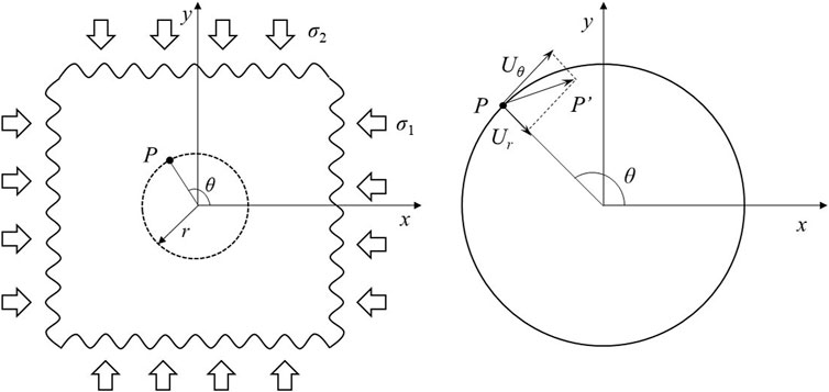
FIGURE 1. Schematic diagram showing the displacement of any point on the borehole wall under two-dimensional stresses.
According to the basic theory of elasticity and rock mechanics, the radial displacement and tangential displacement of any point on the borehole wall P can be expressed as shown in Eq. 1.
The elastic modulus of the thin plate is E, the Poisson’s ratio is μ, and θ is the angle between the radial direction of point P and the positive direction of the x-axis.
As shown in Figure 1, the borehole is deformed under the action of geostress, and the points on the borehole wall change with the displacement. Assuming that the point P is deformed to P′ with the coordinate (x, y), we can get the value of x and y as shown in Eq. 2.
Substituting Eq. 1 into Eq. 2, the coordinates of point P′ can be expressed as shown in Eq. 3.
According to the basic formula of the trigonometric function, we get the following equation as shown in Eq. 4:
Equation 4 is a normal ellipse equation, which proves that the geometrical shape of a circular hole is an ellipse under a two-dimensional plane stress state. In order to establish a better association with the geometric parameters of the ellipse and stress values, we set A and B according to Eq. 5.
Furthermore, we get the magnitude of the two principal stresses as shown in Eq. 6.
In Eq. 6, the relationship between principal stresses and geometric parameters of the borehole (elliptical semi-major axis A and semi-minor axis B and initial radius r) forms the theoretical basis of geostress measurement based on borehole radial deformation (Han, 2018; Han, 2020; Wang, 2018; Wang, 2022). However, in the actual in situ process, it is difficult to obtain the initial radius and the major and minor axes of the ellipse. Therefore, we propose another calculation method based on the borehole radial deformation value, as shown in Eq. 7. By this equation, we do not need the initial radius but only the change values of the major and minor axes of the ellipse.
To determine the basic formula of an ellipse, we need the coordinates of at least three points. According to this basic measurement criterion, a method to determine the elliptic equation based on three radial deformations in different directions is proposed, and a multi-contact measuring device is developed. The global coordinate system is established with the geographic due east direction E as the x-axis and the due north direction N as the y-axis, as shown in Figure 2.
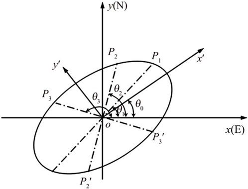
FIGURE 2. Schematic diagram showing how to calculate the ellipse shape parameters by diameters in three different directions.
There are three points, P1, P2, and P3, on the ellipse, and the center symmetry points are represented as
where i = 1, 2, 3.
Let the angle between the major axis (x'-axis) and the x-axis of the ellipse be θ0. The coordinates of P1, P2, and P3 in the local coordinate can be expressed as Eq. 9.
According to the elliptic standard formula, the value of long and short half axes can be obtained by Eq. 10.
To simplify as an example, let the three angles differ by 45°; the direction of the major axis of the ellipse can be calculated by Eq. 11.
From Eq. 11, only the distance and azimuth of three points are included, without any other petrophysical parameters, such as elastic modulus and Poisson’s ratio. The x-axis in Figure 2 points to the east and the angle θ0 represents the direction of the minimum principal stress under compression, while the orientation of the minor axis of the ellipse is the direction of the maximum principal stress. Therefore, the directions of principal stresses can be determined quickly based on the data on the deformed borehole shape without other petrophysical parameters.
According to the measurement principle, a device for measuring radial deformation in different directions has been developed, as shown in Figure 3. The multi-contact design is used to sense the borehole wall displacement changes in multiple directions. Micro-optical imaging is used to measure small deformation of multi-contacts. E-compass is used to obtain the direction values of deformation. The data acquisition component is used to record deformation data autonomously.
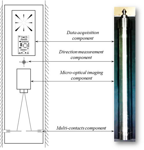
FIGURE 3. Device for borehole radial deformation measurement.
A deep vertical borehole is typically in an environment of water, high temperature, and high permeability, which brings great challenges to the measurement of borehole radial deformation. In order to avoid the impact of complex borehole environments, targeted designs have been carried out.
(1) Multiple groups of rigid contacts with springs are used to sense the change in borehole wall displacement, avoiding tedious operations such as bonding strain gauge and grouting cementation. The other end of the contact is acuminate, which converts the displacement change in the borehole wall into the displacement of the external point of the contact.
(2) The micro-optical imaging technique is used for tracking and measuring the change in the contact external points. A lens with a small longitudinal field angle (which is a relatively long focal length) and an optical imaging unit that matches CCD ensure the imaging measurement of the tiny area. This design avoids the influence of the borehole high-temperature environment on measuring sensors such as strain gauges.
(3) An electronic compass with an accuracy of 0.1° is embedded in the device that can be used for orienting each contact to determine the direction of borehole radial deformation. Then, the direction of the principal stress can be quickly determined according to the shape of the deformed borehole.
(4) The device adopts the design of self-contained data acquisition and record, which can independently complete data acquisition in the borehole, avoiding complex wired transmission problems.
(5) This device can be used to measure borehole radial deformation, but it cannot work independently in the in situ test. It needs to complete the steps of drilling, releasing, and recovering with the cooperation of the drilling rig. It is worth noting that the device can be used with the cooperation of wireline coring drilling tools so as to realize rapid geostress measurement in deep boreholes.
When the contacts are at initial positions, if the initial positions can be calibrated, the actual diameter can be obtained by measuring on this basis. For this reason, a standard reference circle is set. Generally, the circle with the minimum diameter applicable to the contact can be considered. When all the contacts are in the circle, the positions of the contact pins are the initial positions based on the circle. The image can record the initial position and establish the corresponding image coordinates, that is, the image coordinates of the initial position of the reference circle, which constitute the basis for the measurement of the borehole shape.
What we get through the device is the result in the form of an image, and the deformation process in the image is reflected in the form of pixels. Therefore, we assume that the coordinate of the external point of the contact at t time is
Here,
Figure 4 shows a schematic diagram of the diameter-changing process under compression. In this way, the displacement of the borehole wall is converted into the pixel change in micro-optical images. By identifying and calculating the pixel displacement, borehole radial deformation measurement is realized. According to the research on the relationship between borehole radial deformation and geostress in the aforementioned chapters, the magnitude and direction can be calculated.
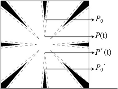
FIGURE 4. Schematic diagram of image displacement recognition.
We mentioned the conversion coefficient γ between image displacement and borehole wall displacement. To determine this coefficient, we carried out calibration tests. The extensometer calibrator is used to trigger the contact to generate the corresponding displacement by generating the standard displacement. The specific calibration process is as follows:
1) Fix the stylus measuring device and the calibration instrument to a fixed bench; the stylus of the contact is coaxial with the measuring axis of the calibration instrument and moves synchronously. 2) Use the measuring shaft of the calibration instrument to push the measuring contact and record the movement of the contact in steps of 0.001 mm in full scale. 3) Determine the starting point position and establish the relationship between the moving distance of the stylus on the image and the actual distance of the calibration instrument based on this so as to obtain the image accuracy, which represents the radial deformation of the unit image coordinate, in mm/pixel.
Assuming that the standard displacement of the measuring axis of the calibration instrument is Sd, and the image displacement (pixel numbers) generated by the change of the stylus is Id, the image accuracy k can be expressed by the following equation, and the unit is mm/pixel:
As shown in Figure 5, the experimental results show that the average image accuracy of the six probes is 6.987 × 10⁻³ mm/pixel; that is, the actual deformation represented by the unit image coordinate is 6.987 × 10⁻³ mm.
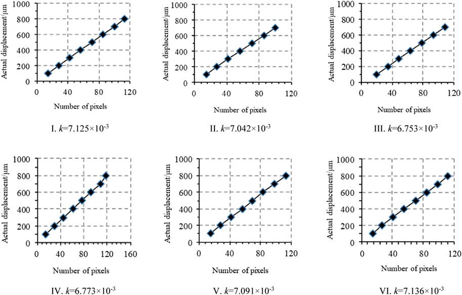
FIGURE 5. Results of the calibration test [(I) result of no. 1 contact; (II) result of no. 2 contact; (III) result of no. 3 contact; (IV) result of no. 4 contact; (V) result of no. 5 contact; and (VI) result of no. 6 contact].
To verify the feasibility of this method for stress measurement, the device is applied to the cube test block with a hole, the cube is pressurized to obtain the hole radial deformation data, and then the corresponding force value causing the radial deformation is calculated. Compared with the actual loading force, the reliability of the calculation results is verified.
The RMT-150C rock mechanics test system is used for the loading test, and the maximum loading force can reach 1,000 KN. The method of uniaxial loading is adopted, and nylon material with uniform texture and good isotropy is selected. The size of the test cube is 150 mm × 150 mm × 150 mm, the elastic modulus is 2.63 GPa, and the middle of the test cube is set with a borehole. The radial deformation measuring device is placed in the hole. The cube is placed on the testing machine for loading, which is loaded step by step to 300 KN in the unit of 50 KN. During the loading process, the displacement changes in the hole wall is sensed, and the test data are collected in the form of video recording. Through identification and calculation of the hole wall deformation, the magnitude of stress is calculated according to Eqs 6, 7.
Before the loading test, the image coordinates of the stylus tip identified by the device can be fitted as a circle. With the increase in the loading pressure, the borehole shape changes, the image coordinates of the contact tip can be fitted as an ellipse, and the ellipse parameters change with the increase in the loading force. The initial diameter of the hole before loading is 41.3 mm. The parameter of the ellipse change with the increase in loading force, according to the hole wall deformation reflected by the tip of the stylus and the initial borehole diameter. When the load reaches 150 KN, the long semi-axis of the deformed ellipse is 20.70 mm and the short semi-axis is 20.49 mm; when the load reaches 300 KN, the long semi-axis of the ellipse is 20.76 mm and the short semi-axis is 20.33 mm.
The magnitude and direction of stress causing the deformation are calculated by using the elliptical shape parameters after borehole deformation. As shown in Figure 6, the deviation between the calculated stress and the actual loading stress value is within the range of 1.5%–7.6%, and the deviation between the principal stress and the actual loading direction is within the range of 1.32°–4.42°.
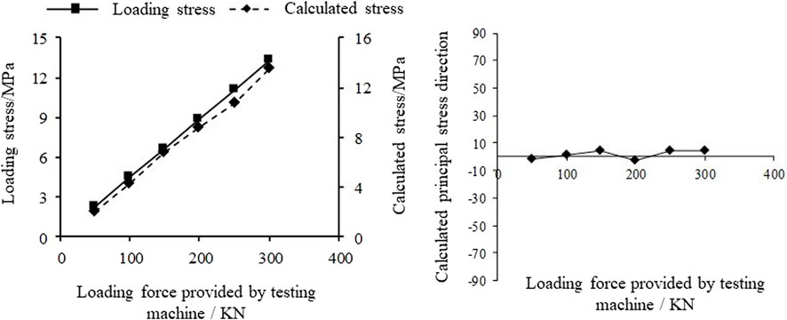
FIGURE 6. Results of the loading test (the left figure shows the comparison between calculated stress and loading stress; the right figure shows the calculated stress direction).
Geostress measurement using a borehole radial deformation measuring device has been carried out in a deep vertical borehole in Xishui City, Guizhou Province, China. The measuring point position is located at 636.6 m depth of the borehole, which is 122 mm in diameter. First, a measuring borehole with a diameter of 40–42.5 mm is drilled in the target test position. Then, the diametrical borehole deformation measuring device is placed in the measuring hole, and the changes in borehole diameter in multiple directions are recorded throughout the whole process. Finally, the drilling of a 122-mm-diameter hole is continued to realize the stress relief. The downhole measurement is completed, and the measuring device is recovered, as shown in Figure 7.
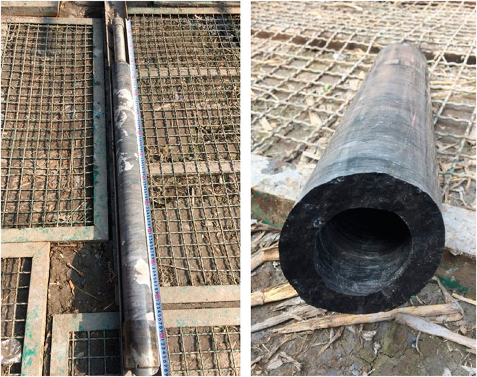
FIGURE 7. Photos of site application (the device and ring core are successfully recovered from the borehole).
A total of five directions of diametrical deformation results are successfully collected. According to the principle of permutation and combination, 10 groups of different combinations can be obtained by arranging the deformation data in any three diametrical directions. Through simultaneous calculation equations, 10 groups of in situ stress calculation results can be obtained. Taking the stress direction as the screening basis, the calculation results of the remaining three groups of in situ stress are obtained by eliminating the obvious abnormal calculation results. The maximum horizontal principal stress at 636.6 m is 23.14 MPa, the minimum horizontal principal stress is 16.59 MPa, and the direction of the maximum horizontal principal stress is 181.3°.
In this test section, the hydraulic fracturing test was also carried out. In addition, all the pressure data during the pressurization process were obtained, which can be used to verify the method in this paper. The results of the hydraulic fracturing test are as follows: 1) the maximum value of pressure is crack rupture pressure, Pb = 36.2 MPa. 2) When the pump is shut off, the shutdown pressure is Ps = 17.6 MPa. 3) When the crack rupture pressure is reached, the displacement of the pump is Q = 243.6 m3/h.
According to the principle of the HF method, the maximum horizontal principal stress is 21.67 MPa, and the minimum horizontal principal stress is 17.6 MPa. The results of in situ stress obtained by borehole deformation and hydraulic fracturing methods are almost the same in magnitude.
As shown in Eq. 6, the calculation results of in situ stress are related to the rock elastic modulus E, Poisson’s ratio μ, ellipse semi-axis, and borehole initial radius. Among them, elastic modulus E and Poisson’s ratio μ are petrophysical parameters that can be obtained by the loading test. The semi-axis of the ellipse can be measured in situ. The main error of in situ stress comes from the initial radius r of the borehole on the premise of ensuring the accuracy of measurement.
Set the radius of the drilling bit as rb; if the initial radius is taken as the radius of the drilling bit, that is, r = rb, Eq. 6 shows that
where σ1 and σ2 are the maximum and minimum principal stresses.
There are errors in the actual borehole radius, so set the initial radius as the radius of the drilling bit
Then,
where
Taking the maximum principal stress
Through Eqs 16, 19, the following result can be obtained:
Since P is far less than 1, Eq. 22 can be simplified as follows:
The molecular part of Eq. 23 can be understood as the radius error caused by the drilling process, while the denominator part can be considered the radius deformation caused by the force. Therefore, the stress error is proportional to the radius size error and inversely proportional to the radius deformation.
From Eq. 14, we obtain the following:
It can be seen from Eq. 25 that the error of principal stress is inversely proportional to the magnitude of principal stress; that is, the larger the principal stress, the smaller the calculation error of stress. The error of principal stress is proportional to the radius error P; that is, the larger the radius error, the greater the calculation error of principal stress.
Through the aforementioned error analysis, there are some applicable conditions and operating points in the process of geostress measurement based on borehole radial deformation, which can be summarized as follows: 1) strictly control the quality of the borehole, especially the radius error. 2) This method is more suitable for larger diameter boreholes because the deformation of borehole diameter is usually larger, which is favorable for measurement. 3) This method is more suitable for deep boreholes because the geostress is usually large and the radial deformation caused by stress is also large. 4) This method can quickly determine the direction of principal stress without petrophysical parameters and initial radius; it just needs to measure the deformed borehole shape.
Based on the elastic theory, theoretical research on the geometric shape of the deformed borehole is carried out. The mathematical proof that the geometric shape of the deformed borehole is an ellipse is given, the relationship between the stress magnitude and the ellipse characteristic parameters is established, and the determination method of the ellipse characteristic parameters is proposed, which lays a theoretical foundation for the geostress measurement based on the borehole radial deformation method. Through the research on the measurement technique of elliptical shape, a contact-type micro-optical radial deformation measurement technology is proposed. The feasibility of the technology is analyzed in principle, and the possible problems in the process of in situ stress measurement are discussed. Through indoor tests and site application, the operability of the method and device is verified. It provides a new idea for geostress measurement in deep boreholes. The main conclusions are as follows:
(1) Under the action of two-dimensional plane stress, the geometric shape of the circular hole after deformation is an ellipse, and there is a specific relationship between the ellipse parameters and the force magnitude.
(2) The magnitude of principal stress can be determined by elliptical parameters and is related to elastic modulus, Poisson’s ratio, and initial borehole diameter.
(3) The direction of principal stress can be determined directly by ellipse shape and is independent of petrophysical parameters and initial radius.
(4) The contact micro-optical borehole shape measuring technology can effectively obtain borehole shape parameters, which provides technical support for in situ stress measurement based on borehole shape. The results of the indoor test also verify the feasibility of technical principles and the correctness of the measurement method. This paper provides a new idea and method for in situ stress measurement in deep boreholes.
The raw data supporting the conclusion of this article will be made available by the authors, without undue reservation.
ZH: conceptualization, methodology, and writing—original draft preparation. ML: investigation and data curation. CW: formal analysis. JW: investigation and supervision. XH: writing—review and editing and funding acquisition.
This research was funded by the Key Research and Development Program of Hubei Province (grant number 2021BAA201) and the Systematic Project of Guangxi Key Laboratory of Disaster Prevention and Engineering Safety (grant number 2020ZDK015).
The authors would like to express deep gratitude to the editors and reviewers for their valuable comments and suggestions that greatly improved this paper.
The authors declare that the research was conducted in the absence of any commercial or financial relationships that could be construed as a potential conflict of interest.
All claims expressed in this article are solely those of the authors and do not necessarily represent those of their affiliated organizations, or those of the publisher, the editors, and the reviewers. Any product that may be evaluated in this article, or claim that may be made by its manufacturer, is not guaranteed or endorsed by the publisher.
Amadei, B., and Stephansson, O. (1986). Rock stress and its measurement. London: Centek Publishers, 95–116.
Fang, X., Feng, H., Wang, Y., and Fan, T. (2022). Prediction method and distribution characteristics of in situ stress based on borehole deformation—a case study of coal measure stratum in shizhuang block, qinshui basin. Front. Earth Sci. 10, 961311. doi:10.3389/feart.2022.961311
Funato, A., and Ito, T. (2017). A new method of diametrical core deformation analysis for in-situ stress measurements. Int. J. Rock. Mech. Min. Sci. 91, 112–118. doi:10.1016/j.ijrmms.2016.11.002
Han, Z., Wang, C., and Zou, X. (2018). Application of borehole stereo pair imaging technology in borehole wall caving in-situ stress measurement. J. Rock. Mech. Eng. 37 (A02), 4177–4183. doi:10.13722/j.cnki.jrme.2017.1192
Han, Z., Wang, C., Wang, Y., Wang, C., Wang, C., et al. (2020). Borehole cross-sectional shape analysis under in situ stress. Int. J. Geomech. 20 (6), 04020045. doi:10.1061/(ASCE)GM.1943-5622.0001687
Jaeger, J. C., Cook, N. G. W., and Zimmerman, R. W. (2009). Fundamentals of rock mechanics. Chichester, U.K: John Wiley & Sons.
Leeman, E. R. (1967). The borehole deformation type of rock stress measuring instrument. Int. J. Rock. Mech. Min. Sci. 4 (1), 23–44. doi:10.1016/0148-9062(67)90003-4
Merrill, R. (1967). Three-component borehole deformation gage for determining the stress in rock. U.S. Bureau of Mines RI. No. 7015, 1967.
Obara, Y., Shin, T., and Yoshinaga, T. (2010). Development of cross-sectional borehole deformation method (CBDM) for measurement of rock stress change. J. MMIJ 67, 9–19. doi:10.2473/journalofmmij.127.20
Obara, Y., and Sugawara, K. (2003). Updating the use of the CCBO cell in Japan: Overcoring case studies. Int. J. Rock. Mech. Min. Sci. 40 (7-8), 1189–1203. doi:10.1016/j.ijrmms.2003.07.007
Wang, C., Han, Z., Wang, J., Wang, Y., et al. (2016). Study of borehole geometric shape features under plane stress state. J. Rock. Mech. Eng. 35 (S1), 2836–2842. doi:10.13722/j.cnki.jrme.2015.1045
Wang, C., Wang, Y., Han, Z., Wang, J., and Zou, X. (2018). A system for measuring borehole diametric deformation based on mechanical contact and micro-optical imaging. Measurement 130, 191–197. doi:10.1016/j.measurement.2018.07.088
Wang, J., Wang, C., Huang, J., Han, Z., Zeng, W., and Wang, Y. (2022). In situ stress measurement method of deep borehole based on multi-array ultrasonic scanning technology. Front. Earth Sci. 10, 933286. doi:10.3389/feart.2022.933286
Wang, L., Pan, L., and Liao, C. (1991). In-situ stress measurement and its application in engineering. Beijing: Geological Publishing House.
Yokoyama, T., Sano, O., Hirata, A., Ogawa, K., Nakayama, Y., Ishida, T., et al. (2014). Development of borehole-jack fracturing technique for in situ stress measurement. Int. J. Rock. Mech. Min. Sci. 67, 9–19. doi:10.1016/j.ijrmms.2013.12.008
Zang, A., and Stephansson, O. (2010). Stress field of the earth’s crust. Dordrecht: Springer, 55–132.
Keywords: geostress measurement, borehole radial deformation, stress relief method, micro-optical imaging, deep borehole
Citation: Han Z, Li M, Wang C, Wang J and Huang X (2023) Application and discussion of the borehole radial deformation method in deep borehole geostress measurement. Front. Earth Sci. 11:1102276. doi: 10.3389/feart.2023.1102276
Received: 18 November 2022; Accepted: 06 April 2023;
Published: 21 April 2023.
Edited by:
Maxim Lebedev, Curtin University, AustraliaReviewed by:
Wang Yun, China University of Geosciences, ChinaCopyright © 2023 Han, Li, Wang, Wang and Huang. This is an open-access article distributed under the terms of the Creative Commons Attribution License (CC BY). The use, distribution or reproduction in other forums is permitted, provided the original author(s) and the copyright owner(s) are credited and that the original publication in this journal is cited, in accordance with accepted academic practice. No use, distribution or reproduction is permitted which does not comply with these terms.
*Correspondence: Xiaohua Huang, aHhoZ3h1QDE2My5jb20=
Disclaimer: All claims expressed in this article are solely those of the authors and do not necessarily represent those of their affiliated organizations, or those of the publisher, the editors and the reviewers. Any product that may be evaluated in this article or claim that may be made by its manufacturer is not guaranteed or endorsed by the publisher.
Research integrity at Frontiers
Learn more about the work of our research integrity team to safeguard the quality of each article we publish.