- 1Sichuan University of Science and Engineering, Zigong, China
- 2CNPC Engineering Technology R and D Company Limited, Beijing, China
- 3Southwest Petroleum University, Chengdu, China
- 4Shanxi Stangshenghe Oil and Gas Field Engineering Technology Service Co, Ltd, Shanxi, China
Casing pressure during well-killing is both an unknown variable that must be addressed and a time-dependent function. Therefore, the calculation of the dynamic reaction of wellbore pressure during well-killing is a dynamic indeterminate boundary problem. Due to the intricacy of the analytical solution technique, finding an analytical solution for the dynamic issue of uncertain boundaries is nearly impossible. Current numerical simulation software is only capable of resolving problems with defined bounds (such as flow or pressure) and is incapable of continuously calculating the wellbore pressure, which varies dynamically with well-killing time. Developing a dynamic reaction computation method for wellbore pressure during well-killing can solve this issue. Based on the mathematical model and definite solution conditions of the wellbore pressure dynamic response under well-killing conditions, this paper applies the finite difference principle and constructs the calculation method of choke and kill wellbore pressure dynamic response through reasonable mesh division of wellbore and gradual iteration of the calculation process. The resultsdemonstrate that the maximum wellhead casing pressure value and the time node of peak value are both highly congruent with the measured data, indicating the method’s high reliability and highlighting its significance for the progress of oil and gas well control safety.
1 Introduction
Due to the complexity of the formation fluid pressure system and the influence of subjective and objective factors during the drilling operation, the initial pressure equilibrium in the wellbore will be broken, resulting in overflow. The fluid from the formation will enter the well. In the absence of timely well-killing, restoring and rebuilding pressure equilibrium will result in a well kick or blowout (Wei et al., 2020). Consequently, well control is one of the most important technologies for ensuringthe safety of drilling and is essential for discovering and developing oil and gas reserves.
Well-killing technology is the core content and most important component of well control (Jin et al., 2016). There are many methods for well-killing under different conditions (such as the driller method, engineer method, circulation and weighting method, etc.). Whatever well-killing technique is used, an acceptable wellhead casing pressure value should be applied by regulating the flow control valve’s opening in accordance with the variation law of bottom hole pressure. To repair and reestablish the wellbore pressure balance, the fundamental rule of ensuring that the bottom hole pressure is slightly higher than the formation pressure is adhered to.
Well-killing is an effective method to solve the pressure imbalance at the bottom of the well (Liang et al., 2021). The wellbore pressure is managed when operating in high-pressure reservoirs, particularly those with gas intrusion, by altering the flow control valve’s opening (Hu et al., 2017; Zhang et al., 2023). Back pressure is generated at the wellhead and acts on the whole wellbore, which can effectively slow or restrain gas intrusion and rebuild the wellbore pressure balance (Yan et al., 2018; Liao et al., 2020). The success of the kill depends on the analysis of wellbore pressure.
Engineering experience demonstrates that standpipe pressure control method is an excellent fit for permeable reservoirs with wide pressure safety windows, such as sandstone reservoirs. In recent years, however, there have been numerous failures in well-killing and throttling operations, particularly for pressure-sensitive reservoirs with narrow pressure safety windows (such as fractured reservoirs and high-pressure gas wells), which has become a significant issue that gravely compromises well control safety.
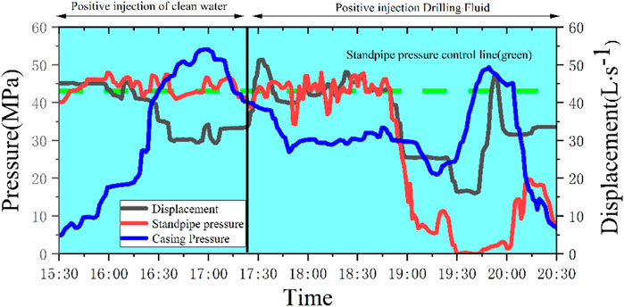
The standpipe pressure control value expected for Well X1 during well-killing is 43Mpa, as can be seen from Figure 1. The standpipe pressure control by driller method is used. However, in practice, it is impossible to hold the standpipe pressure at the desired control value; instead, it varies sharply up and down (for example, at 18:10, the standpipe pressure is about 34 MPa, absolute error is 9 Mpa, the relative error is 21 percent). Too little standpipe pressure will not ensure that the bottom hole pressure is slightly higher than the fundamental principle of formation pressure for reservoirs with narrow pressure safety windows, and the wellbore pressure will be out of balance, leading to secondary overflow and well-killing failure. Inaccurate pressure regulation is the cause of failure. Since there is currently no practical way to increase pressure control accuracy, well-killing success rates are low for pressure-sensitive reservoirs with small pressure safety windows. To achieve the requirements, precise casing pressure control must be used. To increase the success rate of wells, it is essential to increase the accuracy of wellbore pressure management during well-killing.
Nowadays there are many analytical studies on wellbore pressure, such as Pedersen Torbjørn (Pedersen et al., 2018). Using a suitable mechanistic model, they investigate the application of non-linear model predictive control (NMPC) for multivariate control of pressure and flow during under-balanced drilling (UBD). Aarsnes U.J.F. et al. (Aarsnes et al., 2015) calculated and analyzed the pressure at the bottom of the well during managed pressure drilling (MPD). Ma Z (Ma et al., 2016) created a model that can more precisely estimate the parameters in MPD after analyzing the regularity of wellbore pressure variation. Fjelde, K et al. (Fjelde et al., 2016) in order to determine the impact of numerical dissipation and mesh refinement on calculation errors in multiphase flow calculations, the wellbore pressure distribution, annular gas volume fraction, and gas rise rate during overflow were examined. Sun Baojiang (Sun and Baojiang, 2016; Zhang et al., 2022), has made in-depth and detailed research on the law of multiphase flow in UBD and analyzed the mathematical model, simulation, and case of multiphase flow. In consideration of gas phase slippage, Yaxin Liu et al. attempts to propose an improved drift-flux correlation concerning the distribution coefficient and drift velocity applying fora wide range of fluid properties, pipe orientations (Liu et al., 2020). The aforementioned study and analysis, however, are mostly focused on the UBD and MPD operating conditions, which are different from those of the well-killing.
Therefore, this paper mainly proposes a new method for dynamic response analysis of wellbore pressure in well-killing. By establishing a physical model and mathematical model of the dynamic response of wellbore pressure in the throttling and killing process, based on the finite difference principle, a reasonable meshing of the wellbore and progressive iteration of the calculation process are adopted to solve the problem, and the dynamic change law of throttling and killing wellhead casing pressure is determined, which provides an effective solution for precise wellbore pressure control.
2 Theoretical model
Domestic and foreign scholars have carried out extensive research on the changes in the wellbore interiors and put forward a relevant model theory. Aarsnes, Ulf Jakob F et al. (Aarsnes, 2016; Aarsnes et al., 2016) proposed a simple gas-liquid two-phase flow model and carried out a steady-state analysis of the system through the drift flux model. Li Zhiyuan (Li et al., 2017) estimate the bottom hole pressure based on the non-linear drilling model. Seyhmus Guner et al. (Guner et al., 2017) analyzed the effect of gas well surge on wellbore pressure. Li Hongtao (Li et al., 2016) Calculate velocity and attenuation coefficient in a borehole based on a two-fluid model. Hajidavalloo Ebrahim (Hajidavalloo et al., 2020) regards the Bingham plastic model as a drilling fluid to simulate drilling operations and determine temperature and pressure distribution in the wellbore. Yang, Hongwei and others (Yang et al., 2022) analyzed the influence of a large variable diameter annulus and complex wellbore temperature in pressure-controlled drilling and established a simplified model of non-isothermal gas-liquid two-phase flow. However, the above models have a little discussion on physical models, mathematical models, and special boundary conditions under specific conditions of throttling and killing, and can not solve the dynamic boundary conditions well, and can not solve the wellbore pressure in throttling and killing process continuously, which seriously restricts the analysis of engineering problems.
In this paper, the method of throttling and killing by the driller is adopted in the process of establishing the mathematical model of the dynamic response of pressure in throttling and killing wellbore. At the same time, well control regulations (Li and Gao, 2019) that use bottom hole pressure to add safety value to formation pressure are adopted. Because the principle of throttling and killing is the same, the modeling process is also applicable to other well-killing methods.
2.1 Physical model of the upward transportation process of the mixed phase segment of the overflow material along the wellbore annulus
During well-killing, the flow of fluid in the wellbore annulus is divided into a drilling fluid single-phase flow segment and a gas-liquid two-phase flow segment. Throttle and kill operations are carried out by positive circulation. The model of the wellbore annulus state is shown in Figure 2.
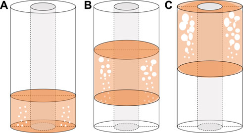
FIGURE 2. A physical model of wellbore annulus state during well-killing (the top of the overflow segment does not reach the wellhead position).
At the initial well-killing time (Liu et al., 2021), the overflow material enters the wellbore in the form of scattered bubble flow and forms an accumulation at the bottom of the well, as shown in Figure 2A; During the process of throttling and killing the well discharge, the overflow material moves from the bottom hole to the wellhead along the wellbore annulus, the volume of overflow material increases with the decrease of wellbore pressure and temperature, and the casing pressure increases, as shown in Figure 2B. When the overflow is transported to the wellhead position, the volume of the overflow increases to the maximum in the wellbore. At this time, the corresponding casing pressure is also the maximum during the killing process, as shown in Figure 2C.
2.2 Physical model of the process of discharging the wellhead in the mixed-phase segment of the overflow material
As shown in Figure 3, when the top of the overflow section reaches the wellhead, throttling and killing operations continue, and the overflow is constantly driven out of the wellhead.
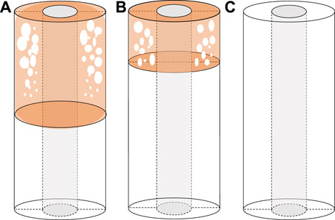
FIGURE 3. A physical model of wellbore annulus state during well-killing (the top of overflow segment reaches wellhead position).
When the top of the overflow reaches the wellhead, the mixed-phase segment of the overflow exists at the wellhead position in a certain flow pattern, as shown in Figure 3A; The well-killing relief operation continues, with the spills continuously pushed out of the wellhead and the wellhead casing pressure value continuously reduced, as shown in Figure 3B; The overflow is completely discharged from the wellbore, and the corresponding wellhead casing pressure is reduced to a minimum, as shown in Figure 3C.
2.3 Gas-liquid two-phase flow model in the wellbore annulus
During well-killing, the drilling fluid and gas-liquid two-phase flow segments of the fluid within the wellbore annulus can be differentiated. By combining the flow structure and form of the gas-liquid two-phase fluid in the wellbore annulus, fundamental equations such as the continuity equation and the momentum conservation equation serve as the basis for the gas-liquid two-phase flow equation. Gas phase slippage will result in changes in gas holdup in different sections and the density of gas-liquid two-phase mixing, thus affecting the dynamic response of well bore pressure. In this paper, the influence of gas phase slippage is considered based on the change in mixture density of the gas and liquid phases. The model is a new method for describing the single-phase - multi-phase fluid mixed-phase flow pattern in the wellbore during well compression, which provides a theoretical basis for the dynamic response behavior of wellbore pressure.
During the modeling process, the following assumptions are used.
1) Ignore the solubility of gas phase of overflow in wellbore annulus;
2) The gas phase in the overflow can be described by the real gas state equation.
3) Ignore the compressibility of drilling fluid;
4) The well bore temperature field is linear and there is no heat exchange between gas and liquid phases at the same location.
5) The overflow accumulates at the bottom of the well in the form of bubbles;
2.3.1 Continuity equation
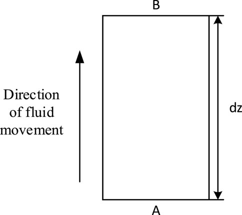
As shown in Figure 4, the segment length is used as the dz micro-element control body for analysis.
The mass of the gas phase and the mass of the liquid phase flow into the micro-element control body from the end face of A to the end face of B in a unit of time, as shown in Eqs 1, 2.
Equations 3 and 4, respectively, give the gas phase mass and liquid phase mass of the outflowing micro-element control body in units of time.
The micro-element simultaneously regulates the gas mass increment as
Gas phase continuity equation
Liquid phase continuity equation
2.3.2 Equation of motion
The law of momentum conservation demonstrates that the rate of change of momentum over time is equal to the sum of forces exerted on the object.
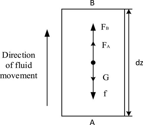
As shown in Figure 5, the segment length is taken as dz a micro-element control body for analysis.
Fluid in the wellbore flows in from section A and out from section B in unit time.
The rate of momentum change of the fluid in the micro-control body is shown in Eqs 8, 9.
The control volume of gas phase momentum variation (i. e. impulse) is
The control volume of liquid momentum change (i. e. impulse) is
Combining Eqs 8, 9, the amount of momentum change of the fluid in the micro-element control body can be obtained.
According to Newton’s second law, the equation of motion of gas-liquid two-phase flow in a well can be obtained within a unit period dt.
It can be seen from the formula that the main force items of the control body are the force items and the friction resistance items in unit time, and the action direction is opposite to the flow direction of the fluid (in the high rectangular coordinate system, the upward direction is positive).
2.3.3 Auxiliary equation
(1) Temperature equation
In general, the displacement of well-killing is low during well-killing. Therefore, from the perspective of the time function, there is adequate heat transfer between the fluid in the wellbore and the formation, i.e., the fluid temperature is roughly equivalent to the formation temperature.
(2) Gas phase density equation
Combining the true gas state equation and the apparent relative molecular mass
(3) Gas Viscosity
The research shows that the method of the indoor experiment is the best way to determine the gas viscosity accurately, but there are practical shortcomings such as long periods and high costs in the method of the indoor experiment. Therefore, in practical applications, a relevant mathematical calculation model is generally used to evaluate the gas viscosity. Dempsey fits the viscosity chart published by Carr et al. The empirical formula obtained is shown in Eq. 14.
Where
2.4 Mathematical model of the upward transport process of the mixed-phase segment of the overflow material along the wellbore annulus
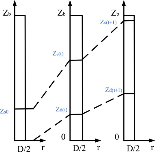
During the upward transportation of the overflow mixed-phase segment along the wellbore annulus, the overflow mixed-phase segment flows with time along the wellbore annulus toward the wellhead position, and the height-rectangular coordinate system describing its state is shown in Figure 6.
2.4.1 Calculation of the height of the bottom of the mixed-phase segment of the overflow material
At time t of the kill operation, the location of the bottom of the mixed-phase segment of the overflow is shown in Eq. 16.
2.4.2 Calculation of the length of the overflowing mixed-phase segment
The recursive relationship equation for the length of the mixed-phase segment of the overflow material is shown in Eqs 17, 18.
The bottom temperature of the overflow mixed-phase segment at the time t of kill is shown in Eq. 19.
Since the initial state (t=0) is known, a recurrence of the length of the overflow mixed-phase segment can be obtained.
2.4.3 Calculation of liquid column pressure
(1) The total column pressure of the single-phase segment of the drilling fluid is shown in Eq. 20.
(2) Total liquid column pressure in the mixed-phase segment of the overflow material
The finite difference method is used to mesh the spatially fixed solution domain of the mixed-phase segment of the overflow at t moment. Using the bottom of the overflow as a starting point and the z-axis as a guide, the micro-segment is taken in turn until the top of the overflow is reached, and m segments are taken.
Within the j micro-segment, the mixed-phase liquid column pressure is shown in Eq. 21.
Then the liquid column pressure within each micro-segment, after superposition, can be obtained from the total liquid column pressure of the mixed-phase segment of the overflow material as shown in Eq. 22.
2.4.4 Calculation of circumferential flow pressure consumption calculation
(1) The total flow pressure consumption of the single-phase segment of drilling fluid is shown in Eq. 23.
(2) Overflow mixed-phase segment flow pressure consumption
At time t, the spatially fixed solution domain of the mixed-phase segment of the overflow is meshed using the same finite difference method. Before calculating the flow pressure dissipation in the jth segment, the flow pattern must be evaluated, and the total flow pressure displacement of the mixed-phase segment of the overflow can be derived by calculating and adding the flow pressure dissipation in each microsegment.
2.4.5 Calculation of wellhead casing pressure
The bottom hole pressure during well-killing is equal to the sum of annulus liquid column pressure, annulus flow pressure loss, and wellhead casing pressure. According to related regulations of well control technology, the bottom hole pressure should be based on the formation pressure provided by the geological design, and an additional safety value should be added. Therefore, at the time of throttle killing t, the wellhead casing pressure is shown in Eq. 25.
2.5 Mathematical model of the process of discharging the wellhead in the mixed-phase segment of the overflow material
The moment the top of the overflow mixed-phase segment reaches the wellhead, it is the end of the upward transportation process of the overflow mixed-phase segment along the wellbore annulus (i.e., the initial moment of the overflow mixed-phase segment discharge process from the wellhead). This is shown in Figure 7.
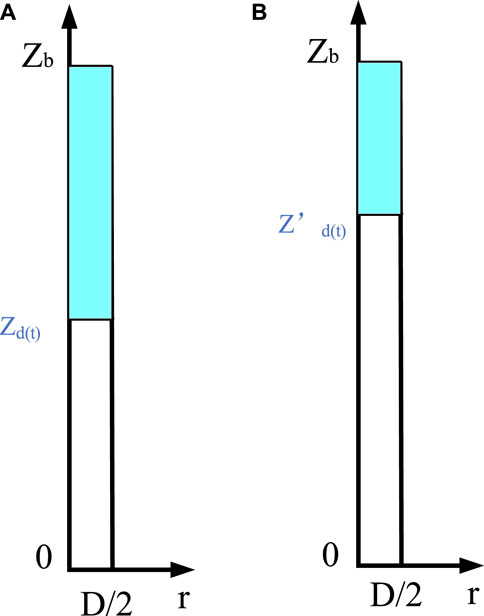
FIGURE 7. Diagram of the height rectangular coordinate system of the process of discharge wellhead of the mixed-phase segment of the overflow. Where (A) the top of the mixed-phase segment reaches the wellhead. (B) The t moment in the process of the mixed-phase segment being discharged.
2.5.1 Calculation of the height of the bottom of the mixed-phase segment of the overflow material
At the t moment when the overflow is discharged from the wellhead, the height of the bottom of the mixed-phase segment of the overflow is shown in Eq. 26.
2.5.2 Calculation of the length of the mixed-phase segment of the overflow material
During the discharge of the overflow mixed-phase segment from the wellhead, only the overflow mixed-phase segment and the continuous single-phase segment of drilling fluid exist in the wellbore annulus, so the length of the overflow mixed-phase segment is shown in Eq. 27.
2.5.3 Calculation of liquid column pressure
(1) Single-phase segment fluid column pressure of drilling fluid
During the discharge of the overflow mixed-phase segment from the wellhead, there is only one single-phase segment of drilling fluid, which is from the bottom of the well to the bottom of the overflow mixed-phase segment.
(2) Liquid column pressure in the mixed-phase segment of the overflow material
The spatially fixed solution domain of the mixed-phase segment at t moments in the process of overflow discharge from the wellhead is meshed using the finite difference method, with the bottom of the overflow as the starting point and the z-axis as the direction, taking microelements in turn until the top of the overflow (taking k segments), then the liquid column pressure within each micro-segment, after superposition, can be obtained from the liquid column pressure of the overflow.
2.5.4 Calculation of flow pressure consumption loss
(1) Single-phase segment flow pressure consumption of drilling fluid
During the discharge of the overflow mixed-phase segment from the wellhead, only a single-phase segment of drilling fluid exists from the bottom of the well to the bottom of the overflow mixed-phase segment, as shown in Eq. 30.
(2) Overflow mixed-phase segment flow pressure consumption
Similarly, the finite difference method is used to mesh the spatially fixed solution domain of the mixed-phase segment of the overflow at t moment. After calculating the flow pressure dissipation in each micro-segment and adding it, the total flow pressure dissipation in the mixed-phase segment of the overflow is obtained, as shown in Eq. 31.
2.5.5 Calculation of casing pressure at throttling and killing wellhead
During the discharge of the mixed-phase segment of the overflow material from the wellhead, the bottom hole pressure is equal to the sum of three items: annular column pressure, flow pressure consumption, and wellhead casing pressure, with an additional safety value.
During the discharge of the overflow material mixed-phase segment from the wellhead, when the fluid column pressure and the annular flow pressure depletion at the t moment of the pressure well are determined, the wellhead casing pressure value at the current time node can be solved for based on the known formation pressure and additional safety pressure, which is the wellhead characteristic parameter of the dynamic response of the wellbore pressure.
3 Calculation method
According to the theoretical model of the dynamic response of wellbore pressure in the well-killing process established and the definite conditions, it is easy to find that the calculation of the dynamic response of wellbore pressure is a dynamic undetermined boundary problem because the well-killing casing pressure is not only a dynamic function of well-killing time but also an unknown term to be demanded. Based on the constructed theoretical model of gas-liquid two-phase flow (Wang et al., 2017; Lou et al., 2022), a new method of dynamic response analysis of wellbore pressure during the compression process was constructed by using the finite difference principle, reasonable grid division of the wellbore, and step-by-step iterations of the calculation process, forming the core technology to solve the problem.
3.1 Calculation flow of upward transportation process of a mixed-phase segment of overflow material along the wellbore annulus
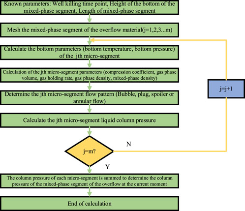
The dynamic calculation flow during the upward transportation of the mixed-phase segment of the overflow material along the wellbore annulus is shown in Figure 8.
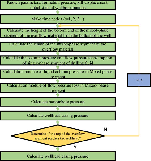
FIGURE 8. Calculation flowchart of the dynamic process of upward transportation of the mixed-phase segment of the overflow material along the wellbore annulus.
Determine the module for calculating the fluid column pressure in the mixed-phase segment at the t moment of the well-killing, and the analysis flow is shown in Figure 9.
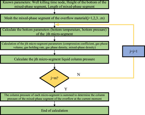
FIGURE 9. Flowchart of liquid column pressure calculation module in the mixed-phase segment during upward transportation.
For the calculation module that determines the flow pressure consumption in the mixed-phase segment at the t moment of the well-killing, the analysis flow is shown in Figure 10.
3.2 Calculation flow of the process of discharging the wellhead of the mixed-phase segment of the overflow material
The dynamic analysis flow during the overflow mixed-phase segment being discharged from the wellhead during well-killing is shown in Figure 11.
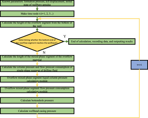
FIGURE 11. Flowchart for calculating the dynamic process of discharge wellhead of a mixed-phase segment of overflow material.
For the calculation module of the liquid column pressure in the mixed-phase segment of the overflow material at t moment of the well-killing, the analysis flow is shown in Figure 12.
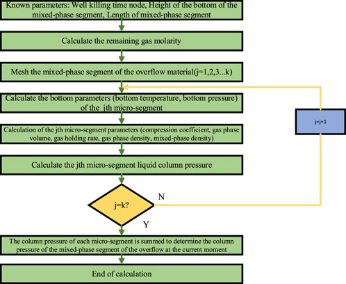
FIGURE 12. Flowchart of the module for calculating the liquid column pressure in the mixed-phase segment during discharge from the wellhead.
For the calculation module that determines the flow pressure consumption in the mixed-phase segment of the overflow material at t moment of the well-killing, the analysis flow is shown in Figure 13.
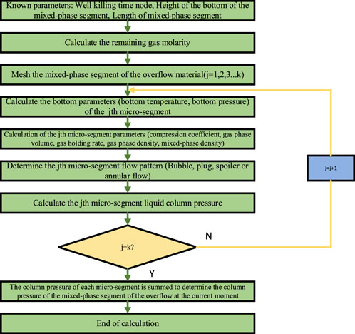
FIGURE 13. Throttling and killing t moment overflow material mixed-phase segment flow pressure consumption calculation module flowchart.
4 Definite solution conditions of a mathematical model
The corresponding boundary conditions of the definite solution are given in conjunction with the specific operating conditions of throttling and killing.
(1) Entrance boundary
In the well-killing condition, the entrance boundary is the bottom of the well.
Inlet flow
During well-killing, the inlet flow rate is the well-killing displacement, which is a known term as shown in Eq. 33.
Inlet pressure
During well-killing, the inlet pressure is the formation pressure, which is also a known term, as shown in Eq. 34.
From Eqs 33, 34, it can be seen that the inlet boundary conditions are known and are constant terms in the process of cyclic discharge of well-killing.
(2) Outlet boundary
In the well-killing condition, the outlet boundary is the wellhead.
Outlet flow
During the well-killing, the outlet flow rate is determined by both the well compression discharge and the incremental volume of the gas phase in the mixed-phase segment of the overflow material, which is an unknown term, as shown in Eq. 35.
Outlet pressure
During well-killing, the outlet pressure is the wellhead casing pressure, which is also an unknown term, as shown in Eq. 36.
From Eqs 35, 36, it can be seen that the outlet boundary conditions are all unknown and terms to be found. That is, the outlet boundary condition is a pending boundary condition during the well-killing.
5 Experimental verification
5.1 Basic data of experimental well
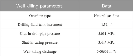
(1) Experimental well-killing parameters, as shown in Table 1.
(2) Well structure parameters, as shown in Table 2.
(3) Drilling fluid parameters, as shown in Table 3.
(4) Other parameters, as shown in Table 4.
5.2 Multi-phase flow model calculation data
Analysis of the initial state of the wellbore annulus
1) Length of a mixed-phase segment of overflow material in the wellbore annulus
The length of the mixed-phase segment of the overflow material in the wellbore annulus was calculated to be 834.98 m.
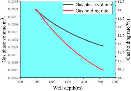
2) Distribution of gas phase volume and gas holding rate in the initial overflow segment
The distribution of gas phase volume and gas holding rate in the mixed phase segment of the overflow. The calculation results are shown in Figure 14.
(2) Dynamic response analysis of wellhead pressure during well-killing
As shown in Figure 15, the wellhead pressure varies dramatically as the overflow mixed-phase segment approaches the wellhead location due to the well pressurization displacement, and the top of the overflow mixed-phase segment reaches the wellhead position 1,135 s later. At this time, the wellhead pressure rises to a high of 6.41 MPa, an increase of 2.97 MPa relative to the initial well pressure (growth of 86.09 percent).
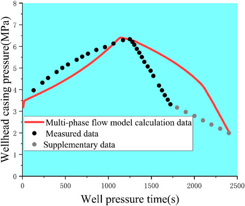
FIGURE 15. Schematic diagrams of the calculation results of each model for the wellhead casing pressure values compared with the actual measured data of the experimental wells.
During the pressure time of 1136s–2410s, the wellhead casing pressure value decreases as the overflow material is continuously jacked out of the wellhead.
5.3 Reliability verification analysis
The wellhead casing pressure results calculated by each of the aforementioned models were compared with the measured data, and the calculated results of each model for the wellhead casing pressure values were compared with the measured data of the experimental wells, as depicted in Figure 15 and Table 5.
During well-killing, the overflow mixed-phase segment is transported upward from the bottom of the well along the wellbore annulus, and the time for the bottom of the overflow mixed-phase segment to reach the wellhead is determined by the pressure discharge, annulus cross-sectional area, and well depth, which are all known quantities, so the actual measured data of the experimental well can be supplemented, as shown in the gray points in Figure 15.
From Figure 15, it can be seen that the calculated results of the dynamic analysis model are closest to the measured data; the maximum wellhead casing pressure value is 6.41MPa, 0.08 MPa larger than the measured data (6.33 MPa), and the error is 1.26 percent; and the peak occurrence time coincides well, occurring only 2 min before the measured data. The accuracy and reliability of the model constructed in this paper are well illustrated.
6 Conclusion
Based on a mathematical model of the dynamic response of wellbore pressure during well-killing and definite solution conditions, a method for calculating the dynamic response of wellbore pressure is established using the finite difference principle, reasonable mesh division of the wellbore, and step-by-step iteration of the calculation, and core technology for solving the problem is established, which is of great significance to the development of well control safety of oil and gas wells.
(1) Engineering practice and theoretical analysis demonstrate that, under complex conditions, such as pressure-sensitive reservoirs, the casing pressure control method can effectively improve the precision of wellbore pressure control and is the fundamental method for increasing the success rate of wells.
(2) The mathematical model of the dynamic response of wellbore pressure is created based on the theory of gas-liquid two-phase flow and the entire well-killing process, and the conditions for defining the mathematical model are specified. By computing the dynamic variation rule of wellhead casing pressure and comparing the observed data of experimental wells, the peak error of casing pressure is only 1.26 percent, which demonstrates the mathematical model’s reliability in its entirety.
(3) The method can accurately describe significant wellbore characteristic parameters such as the variation law of the length of the mixed-phase segment of the overflow material, the distribution law of the gas phase, the variation law of the flow pressure consumption, the distribution law of the wellbore pressure, and the variation law of the wellhead casing pressure, thereby providing a theoretical basis for the precise implementation of wellbore pressure control.
Data availability statement
The original contributions presented in the study are included in the article/supplementary material, further inquiries can be directed to the corresponding author.
Author contributions
PL: Conceptualization, Methodology, Writing - Original Draft Validation, Writing - Review & Editing ZW: Writing - Original Draft, Data Curation CW: Investigation ZT: Formal analysis HY: Software KL: Project administration.
Funding
This work is supported by The Project of Sichuan University of Science and Engineering (No. 2020RC18) and The Key Project of Sichuan Provincial Key Lab of Process Equipment and Control (No. GK202007).
Acknowledgments
We gratefully acknowledge the support received.
Conflict of interest
Author KL was employed by the company Shanxi Stangshenghe Oil and Gas Field Engineering Technology Service Co., Ltd., China. Author CW was employed by the company CNPC Engineering Technology R and D Company Limited.
The remaining authors declare that the research was conducted in the absence of any commercial or financial relationships that could be construed as a potential conflict of interest.
Publisher’s note
All claims expressed in this article are solely those of the authors and do not necessarily represent those of their affiliated organizations, or those of the publisher, the editors and the reviewers. Any product that may be evaluated in this article, or claim that may be made by its manufacturer, is not guaranteed or endorsed by the publisher.
References
Aarsnes, U. J. F. (2016). A methodology for classifying operating regimes in underbalanced-drilling operations.
Aarsnes, U. J. F., Ambrus, A., Vajargah, A. K., Aamo, O. M., and Van Oort, E. (2015). “A Simplified gas-liquid flow model for kick mitigation and control during drilling operations,” in Proceeding of the ASME-2015 Dynamic Systems and Control Division, Columbus, Ohio, USA, October 2015.
Aarsnes, U. J. F., Ambrus, A., Di Meglio, F., Karimi Vajargah, A., Morten Aamo, O., and van Oort, E. (2016). A simplified two-phase flow model using a quasi-equilibrium momentum balance. Int. J. Multiph. Flow 83, 77–85. doi:10.1016/j.ijmultiphaseflow.2016.03.017
Fjelde, K. K., Frøyen, J., and Ghauri, A. A. (2016). “A numerical study of gas kick migration velocities and uncertainty,” in SPE Bergen One Day Seminar, Grieghallen, Bergen, Norway, April 2016.
Guner, S., Elshehabi, T., and Ilkin Bilgesu, H. (2017). “The effects of gas kick migration on wellbore pressure,” in Proceeding of the 2017 AADE National Technical Conference and Exhibition held at the Hilton Houston North Hotel, Houston, Texas, April 2017.
Hajidavalloo, E., Daneh-Dezfuli, A., and Falavand Jozaei, A. (2020). Effect of temperature variation on the accurate prediction of bottom-hole pressure in well drilling. Energy Sources, Part A Recovery, Util. Environ. Eff. 9, 1–22. doi:10.1080/15567036.2020.1797943
Hu, G., Zhang, P., Wang, G., Zhu, H., Li, Q., Zhao, S., et al. (2017). Performance study of erosion resistance on throttle valve of managed pressure drilling. J. Petroleum Sci. Eng. 156, 29–40. doi:10.1016/j.petrol.2017.05.011
Jin, Y., Li, C., and Wu, Q. (2016). Methodology for kick tolerance calculation and well killing in deepwater drilling. Nat. Gas. Ind. B 3 (5), 472–478. doi:10.1016/j.ngib.2016.09.003
Li, X., and Gao, D. (2019). Study on mud weight window prediction model and safety additional value of horizontal well in shales considering effects of Well's extended-reach limit. J. Petroleum Sci. Eng. 173, 579–587. doi:10.1016/j.petrol.2018.10.054
Li, H., Chen, R., Li, X., Meng, Y., Zhu, L., and Zhao, J. (2016). Investigation of pressure wave propagation and attenuation characteristics in wellbore gas-liquid two-phase flow. J. Nat. Gas Sci. Eng. 35, 1088–1100. doi:10.1016/j.jngse.2016.09.020
Li, Z., Hovakimyan, N., and Kaasa, G. (2017). Bottom hole pressure estimation and ℒ1 adaptive control in managed pressure drilling system. Int. J. Adapt. Control Signal Process. 31 (4), 545–561. doi:10.1002/acs.2672
Liang, H., Wei, Q., Lu, D., and Li, Z. (2021). Application of GA-BP neural network algorithm in killing well control system. Neural Comput. Appl. 33 (3), 949–960. doi:10.1007/s00521-020-05298-4
Liao, Y., Sun, X., Sun, B., Wang, Z., Zhang, J., and Lou, W. (2020). Wellhead backpressure control strategies and outflow response characteristics for gas kick during managed pressure drilling. J. Nat. Gas Sci. Eng. 75, 103164. doi:10.1016/j.jngse.2020.103164
Liu, Y., Tong, T. A., Ozbayoglu, E., Yu, M., and Upchurch, E. (2020). An improved drift-flux correlation for gas-liquid two-phase flow in horizontal and vertical upward inclined wells. J. Petroleum Sci. Eng. 195, 107881. doi:10.1016/j.petrol.2020.107881
Liu, P., Zhan, Y., Xiao, Q., Tang, Z., Li, X., and Zuo, L. (2021). A new inversion method of the initial state of annulus in killing. Sci. Prog. 105, 746. doi:10.1177/00368504221102746
Lou, W., Sun, D., Su, X., Li, P. F., Liu, Y. X., Guan, L. C., et al. (2022). High-precision nonisothermal transient wellbore drift flow model suitable for the full flow pattern domain and full dip range. Petroleum Sci. doi:10.1016/j.petsci.2022.11.011
Ma, Z., Vajargah, A., Ambrus, A., Ashok, P., Chen, D., Van Oort, E., et al. (2016). “SPE-181672-MS multi-phase well control analysis during managed pressure drilling operations,” in Proceeding of the SPE Annual Technical Conference and Exhibition, Dubai, UAE, September 2016.
Pedersen, T., Aarsnes, U. J. F., and Godhavn, J. (2018). Flow and pressure control of underbalanced drilling operations using NMPC. J. Process Control 68, 73–85. doi:10.1016/j.jprocont.2018.05.001
Sun and Baojiang (2016). Multiphase flow during underbalanced drilling. John Wiley & Sons Singapore Pte. Ltd.
Wang, N., Sun, B., Gong, P., and Wang, Z. (2017). Improved void fraction correlation for two-phase flow in large-diameter annuli. Chem. Eng. Technol. 40 (4), 745–754. doi:10.1002/ceat.201600119
Wei, L., Yang, X., Xi, C., Hong, C., Yumin, L., and Xueqing, L. (2020). Research and application of downhole blowout prevention system while drilling: A review. J. Petroleum Sci. Eng. 188, 106882. doi:10.1016/j.petrol.2019.106882
Yan, T., Qu, J., Sun, X., Chen, Y., and Pan, Y. (2018). Propagation velocity and time laws of backpressure wave in the wellbore during managed pressure drilling. Nat. Gas. Ind. B 5 (3), 253–260. doi:10.1016/j.ngib.2017.11.009
Yang, H., Li, J., Jiang, J., Zhang, H., Guo, B. Y., Zhang, G., et al. (2022). A dynamic managed pressure well-control method for rapid treatment of gas kick in deepwater managed pressure drilling. Petroleum Sci. 19, 2297–2313. doi:10.1016/j.petsci.2022.06.011
Zhang, Z., Sun, B., Wang, Z., Pan, S., Lou, W., and Sun, D. (2022). Intelligent well killing control method driven by coupling multiphase flow simulation and real-time data. J. Petroleum Sci. Eng. 213, 110337. doi:10.1016/j.petrol.2022.110337
Zhang, Z., Sun, B., Wang, Z., Mu, X., and Sun, D. (2023). Multiphase throttling characteristic analysis and structure optimization design of throttling valve in managed pressure drilling. Energy 262, 125619. doi:10.1016/j.energy.2022.125619
Nomenclature
Parameters definition
Keywords: well-killing, dynamic undetermined boundary, dynamic response, mathematical model, oil and gas well control
Citation: Liu P, Wang Z, Wang C, Tang Z, Yu H, Liu H and Li K (2023) A new approach to analyzing wellbore pressure dynamically in well-killing. Front. Earth Sci. 11:1058391. doi: 10.3389/feart.2023.1058391
Received: 30 September 2022; Accepted: 18 January 2023;
Published: 02 February 2023.
Edited by:
Shengnan Chen, University of Calgary, CanadaReviewed by:
Jianbo Zhang, China University of Petroleum, ChinaWenqiang Lou, Yangtze University, China
Copyright © 2023 Liu, Wang, Wang, Tang, Yu, Liu and Li. This is an open-access article distributed under the terms of the Creative Commons Attribution License (CC BY). The use, distribution or reproduction in other forums is permitted, provided the original author(s) and the copyright owner(s) are credited and that the original publication in this journal is cited, in accordance with accepted academic practice. No use, distribution or reproduction is permitted which does not comply with these terms.
*Correspondence: Zhiping Wang, MjI4NDY1NjE3NEBxcS5jb20=
 Pu Liu1
 Zhiping Wang