 Hua Nan1,2
 Shuai Wang1*
- 1School of Energy Science and Engineering, Henan Polytechnic University, Jiaozuo, Henan, China
- 2Hami Yu Xin Energy Industry Research Institute, Hami, Xinjiang, China
Top coal caving has become one of the main mining methods for thick and extrathick coal seams. Because of coal seam conditions, the top coal thickness is not constant. It is necessary to study the influence of top coal thickness changes on the top-coal-caving mining process. To explore the migration law of top coal failure, the experimental means of similar simulation experiment, numerical simulation experiment and field monitoring data were used. Through a similar simulation test of three different top coal thicknesses, the change rule of top coal migration was analyzed. Moreover, the stress and displacement changes of a 14 m coal seam over a thick top coal caving face were monitored and analyzed comprehensively with the simulation results. The results show that when the top coal thickness is unchanged, the top coal vertical displacement in the upper part is larger than that in the middle part due to the top plate rotation in front of the working face, and the stress change follows an opposite trend. The simulation results were the same as the field test results. When the top coal thickness is changed, whether it is upper top coal or middle top coal, the top coal displacement and stress changes will increase. The top coal migration will be more obvious, and thus the crushing will be more serious.
1 Introduction
Coal has always been a solid backing for the steady and rapid development of China’s economy. China’s annual coal consumption has reached approximately 70%. Therefore, coal has made important contributions to China’s economic development (Si et al., 2015; Wang et al., 2018; Liu et al., 2019). With the adjustment of the national energy structure, it is estimated that by 2050, the consumption ratio of coal as a one-time energy source will not be lower than 50%. In the past two decades, China’s coal industry has developed rapidly. Moreover, thick coal seams are the main coal seams for high yield and high efficiency in China’s coal industry. In China, thick coal seams are commonly found in Shanxi, Xinjiang, and Inner Mongolia. With the rapid application of mechanized mining techniques, thick coal seam mining currently mainly relies on top coal caving. However, thick coal seams tend to induce wide-reaching strata movements, complex stress distributions, and intensive strata behaviors in working faces because of their high efficiencies and rich production during the mining process. This is particularly true when coal seams are covered by overlying thick coal seams during mining. The long breakages, long weighting steps, and their far-reaching effects intensify the strata behaviors in working faces (Yu et al., 2020a; Yu et al., 2020b). Production practices have resulted in frequent strong strata behaviors of working faces after thick coal seam mining (Tan et al., 2010; Zheng et al., 2015; Zhang et al., 2016; Bai et al., 2017; Lan et al., 2018; Liu et al., 2020).
Research on fully mechanized coal mining technology mainly focuses on France, the Soviet Union, Russia and other countries. Around the late 1940s and early 1950s, some countries represented by France gradually adopted caving coal mining methods. However, due to the influences of both social and technological factors, some European countries represented by France did not use this method and achieved good technical and economic results (Liu, 2018). In the 1970s, the Soviet Union conducted the mechanized mining of a large-dip-angle coal seam and developed mining applications for large dip angles and all kinds of steep-seam fully mechanized stents and coal winning machines, and on the basis of an especially large angle 45° above the coal seam mining process, basically laid the foundation of science and technology in the mining of deeply inclined coal seams (Schgal and Coalfields Kumar, 1992; Bondarenko et al., 1993). A. Vakili et al. and B. Unver. also conducted relevant studies (Unver and Yasitli, 2006; Habib and Brett, 2010; Vakili and Hebblewhite, 2010; Mahdi and Charlie, 2012). Similarly, China has made many top coal mining research achievements. Other researchers have also studied in this field in different ways (S Bai and H Tu, 2020; Zhou et al., 2022; Zhang et al., 2020; Zhang and Zhang, 2019; Xie and Zhou, 2008) . In general, the research and application of thick coal seam mining technology in China is at the world’s leading level.
According to China Coal seam thickness classification standard, coal seam thickness more than 8 m is called extra thick coal seam. Thick coal seam mining methods in China mainly include layered mining, full mining, and top coal mining (Xia et al., 2017; Duan et al., 2018; Szurgacz and Brodny, 2018; Zou and Lin, 2018; Lv et al., 2019; Zhai et al., 2019). In China, top coal mining technology has been extensively promoted due to its wide adaptability, and it has become one of the main thick coal seam mining methods in China. The basic principle of the caving mining method is to arrange a long wall working face with a normal mining height along the bottom of a thick coal seam (or section) at the beginning of the mining process. Conventional mining methods are used to stope the working face. By means of the action of mine pressure (top coal forms many penetrating fractures in the range of the leading stress peak area, and roof rotation simultaneously accelerates top coal crushing) and the mechanical characteristics of the coal and rock mass, the top coal above the support is broken and dispersed. It is then released from the coal discharge port behind (or above) the support and finally transported out of the working surface by a scraper conveyor. According to the working face layout, top coal mining is divided into one-time full-thickness caving coal mining, premining top-layered caving coal mining, multilayer top coal mining, and steeply inclined horizontal-section caving coal mining (Ma et al., 2016; Guo et al., 2017; Wu, 2017; Zhu, 2017; Wang, 2018). The success of the fully mechanized thick coal seam caving method is positively correlated to top coal fracturing. During fully mechanized thick coal seam caving mining, a series of mining processes, such as the stressing, deformation, migration, and crushing of top coal, have certain specialties (Wang, 2006; Mao and Yao, 2010; Huang et al., 2015; Li, 2015; Jiang et al., 2016; Wang, 2016; Li et al., 2021b). There are many factors affecting top coal movement, and the most important is geological conditions. The geological conditions mainly include the coal seam strength, pinch condition, development and distribution of geologically weak surfaces (fractures, joints, etc.), top coal thickness, mining depth, and roof lithology. We can see from initial research results that the largest factor affecting top coal output is the unique structure that it produces during the entire extrathick coal seam caving process. Therefore, top coal quality is also the result of a combination of factors (Nan et al., 2005; Wang, 2008; Nan et al., 2010; Li, 2013; Feng, 2014; Wang et al., 2015; Zhong, 2015; Ma, 2016; Cheng et al., 2017; Kong et al., 2018; Wang et al., 2019; Li et al., 2021a). However, researchers have studied the relationships between different coal seam heights and roof collapse displacement and working face coal wall distance by means of field measurements and similar simulations, etc., and obtained the top coal starting point location and top coal migration law in the front and rear of fully mechanized caving working faces (Meng et al., 2003; Zhai et al., 2009; Qian et al., 2010; Yang et al., 2011; Zhu and Yan, 2011; Liu et al., 2022).
But in the process of coal seam mining, the change of coal seam is irregular, and the thickness of top coal changes with the irregular change of coal seam, which has a very important influence on the migration law and stress change characteristics of top coal in working face. Therefore, based on this problem, in this paper, using the experimental means of similar simulation experiment, numerical simulation experiment and field monitoring data, the caving and crushing characteristics and migration law of top coal in the mining stage are systematically analyzed and studied. The mechanism of top coal crushing is revealed and the influence law of sudden change of coal thickness on top coal migration and stress in the process of super thick fully mechanized caving mining is clarified. It is of great scientific significance and application value to provide theoretical support for the successful application of fully mechanized extrathick coal seam caving mining technology.
2 Similar simulation test of top coal with different thicknesses
This study takes 21121 fully mechanized caving face of Qianqiu Coal Mine in Yima Coal Industry as the background. 21121 face strike length 1386–1442 m; Inclination length 132 m; Coal seam inclination 13º55’; The thickness of coal seam is 12.55–17.16 m, with an average thickness of 13.81 m. The working face adopts comprehensive mechanized caving mining, and the cutting height of the shearer is 3.2 m.
2.1 Parameter acquisition of the model
After sample analysis and research, the corresponding conclusions are drawn: the immediate roof is composed of dark gray–black dense mudstone interbedded with very thin and fine sandstone and siltstone; the basic tops are composed of Middle Jurassic variously layered conglomerate, sandstone and siltstone. The bottom plate is composed of conglomerate. Therefore, the objects of this experiment are siltstone, mudstone, coal seam, conglomerate and sand-bearing conglomerate.
2.1.1 Density
Density refers to the mass in a unit volume of matter, which is calculated according to formula 1 (Ma, 2016):
M -- quality of sample, kg;
V -- volume of sample, m3.
2.1.2 Compressive strength
Compressive strength refers to the maximum compressive stress per unit area of a material under the condition of no lateral constraints. It is calculated according to formula 2 (Yang et al., 2011):
P -- force on the specimen when it is damaged, KN;
A -- cross-sectional area of the specimen, m2.
The compressive strength, Young’s modulus and Poisson’s ratio mechanical parameters of the samples can be obtained by sorting and averaging the data obtained in the experiment.
Through formulas 3, 4 (Yang et al., 2011), the bulk modulus K and shear modulus G of a specimen can be obtained from the Young’s modulus E and Poisson’s ratio v of the specimen.
2.1.3 Tensile strength
Tensile strength is the maximum stress that a sample can bear before it breaks. The tensile strength is measured by the splitting method in this experiment and calculated according to formula 5 (Ma, 2016):
P -- force on the specimen when it is damaged, KN;
d -- height of cubic specimen, m;
t -- width of cubic specimen, m.
2.1.4 Shear strength
Shear strength refers to the ratio of shear force and shear section area when a specimen is subjected to shear force on a shear plane under the condition of normal stress. The indexes used to measure the shear strength are the internal friction angle and cohesion force. The calculation formulas are shown in formulas 6 and 7 (Yang et al., 2011).
P -- force on the specimen during failure, KN;
F -- shear plane area, m2;
α -- angle of shear fixture.
2.2 Similar simulation test
A total of three simulation tests were performed for comparative study. The second one took the original condition of the caving coal face as the simulation condition. The coal thickness of the first aircraft decreased from 2 to 11.8 m, and the other parameters were the same as those of the second aircraft. The coal thickness of the third aircraft increased by 2–15.8 m, and the other parameters were the same as those of the second aircraft.
The model block size was 160 x 160 x 40 cm3. The loading system adopted a JSF300T-VIII2.5–31.5A2 high-precision static servo hydraulic console, which realized active loading on three sides above the left and right boundaries of the model. The maximum load concentration at the boundary of the model was 5 MPa. At both ends of the frame, the lateral center position was equipped with a plane rotating support shaft. The support shaft could flip the plane through the bearing seat fixed on the ground, which realized the simulation test of the inclination angle of different coal (rock) strata. The test instrument is shown in Figure 1. The basic structural elements of this section are (Figure 1): The framework of the mining engineering physical model test equipment (1), axial hydraulic jack (2), help plates (3), similar simulated strata (4), right-side hydraulic jack (5), and left-side hydraulic jack (6).
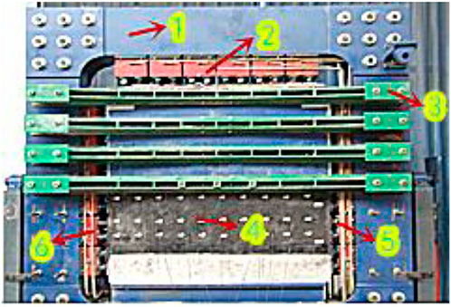
FIGURE 1. Similar simulation test model.
Similar simulation test design: River sand was used as the aggregate, and gypsum, calcium carbonate and cement were used as the cementing materials. The layered material was talcum powder. Frame contact with polyethylene friction material was made with oil to reduce friction.
Test calculation: During the test, similarity criteria, such as geometric similarity, bulk density similarity, strength similarity and time similarity, were strictly observed between the model and prototype. Each similarity constant satisfied the following relationship:
Take the geometric similarity constant
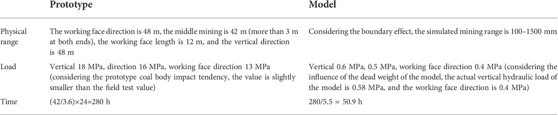
TABLE 1. Comparison list of entity and model parameters.
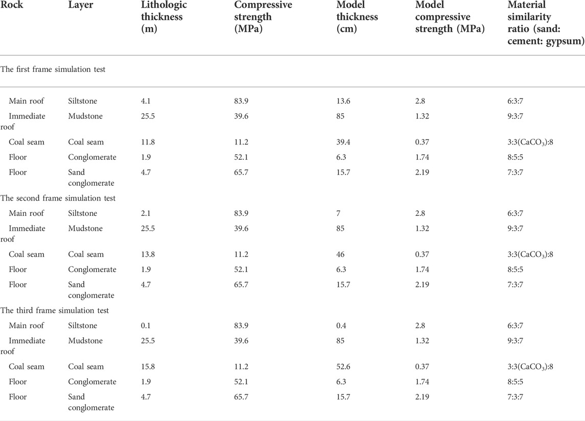
TABLE 2. List of parameters selected for the different frame simulation tests.
Arrangement of measurement points: A stress test method with an embedded pressure gauge was used. The pressure gauge was a dyb-1 miniature resistance strain soil pressure gauge with a specification of 1.0 MPa and an appearance of 7/35 H/Φ (mm); a Model YJZ digital static resistance strain gauge.
Arrangement of stress observation points: The model coal seam was directly buried, and group II was arranged. The group I distance model coal seam had a roof of 277 mm (the second frame was 310 mm; the third frame was 343 mm); group II was 60 mm away from the coal seam roof of the model (all three of them had the same value). Each group was evenly equipped with six pieces (and one piece for every 200 mm) along the 1000 mm length in the middle, with a total of 12 measuring points for each piece.
Displacement: The total station instrument was used to test the placement points. In the simulation test of similar materials, a gts-602a digital electronic total station instrument was used for observation with an observation accuracy of m<±0.1 mm.
3 Similar simulation results
3.1 Top coal migration and crushing results
The top coal migration and fragmentation in the mining processes of the three models are shown in Figure 2.
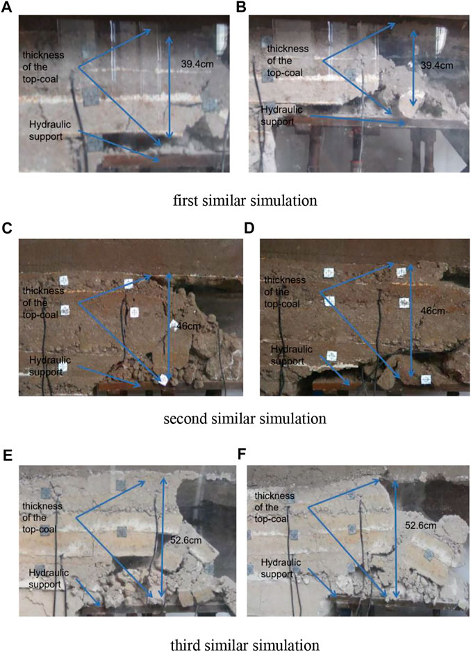
FIGURE 2. Different similar simulation diagrams of top coal migration and fragmentation. (A,B) respectively represent the crushing condition of top coal during and after stabilization of the first similar simulation excavation. (C,D) respectively represent the crushing condition of top coal during excavation and after stabilization of the second similar simulation. (E,F) respectively represent the crushing condition of top coal during and after stabilization of the third similar simulation excavation
The top coal thickness in the first simulation test was 394 mm. Before the support was repeatedly raised and lowered, the thin upper top coal in the coal and rock joint was crushed more fully. Due to the stress state of the coal body and the forward movement of the support, the thin upper top coal of the support was crushed more fully. However, the top coal in the middle had a short beam structure. The brachiform short beam structure was destroyed after the support was raised and lowered repeatedly. Only the front half of the top beam of the support showed a brachiform short beam structure. After the destruction, large blocks of coal were neatly arranged. The top coal in the back half of the top beam of the support was completely broken and flowed toward the cover beam.
The top coal thickness in the second simulated test was 460 mm. Under the joint action of leading abutment pressure, roof rotation and support, the top coal under this condition was fully broken near the cover beam, and the roof presented a more regular collapse. In this test, it was more obvious that the thin upper top coal at the coal and rock junction was compressed in the range of 0.2–0.4 m in front of the working face to the coal wall of the working face.
The top coal thickness in the third simulated test was 526 mm. Under the joint action of leading abutment pressure, roof rotation and support, the top coal was broken near the shield beam under this condition, but the lumpiness was obviously higher than that of the second simulated test. In the range from 0.3 to 0.6 m in front of the working face to the coal wall of the working face, the thin upper top coal of the coal and rock joint showed the phenomenon of compaction, and the compaction of the top coal was thicker than that of the second frame. The initial collapse of the overburdened rock was more severe, and the pressure box was crushed instantly. Due to the large top coal thickness and insufficient top coal crushing, the broken top coal at the middle and lower parts and the top coal above the support experienced obvious separation, and there was a structural layer of the short top coal beam with good integrity at the end of the support.
In general, the top coal crushing degree in front of the working face gradually weakened from top to bottom, and the upper coal body above the support and near the top of the coal wall was dominated by a wedge crack at approximately 60° in the advancing direction of the working face. However, the middle and lower top coal was dominated by cracks at approximately 45° in the advancing direction of the working face. The top coal failure process of the extrathick coal seam under the action of abutment pressure mainly involved fracturing and shearing. The upper top coal failure mainly involved the formation of tiny cracks by abutment pressure and shear failure, and under the action of the roof rotation moment, the pushing direction of the working face was approximately 60° with respect to the wedge penetrating cracks formed due to tensile stress, which greatly increased the upper top coal crushing degree.
3.2 Pressure results
The pressure test results of the three comparative similar simulation tests are shown in Figure 3.
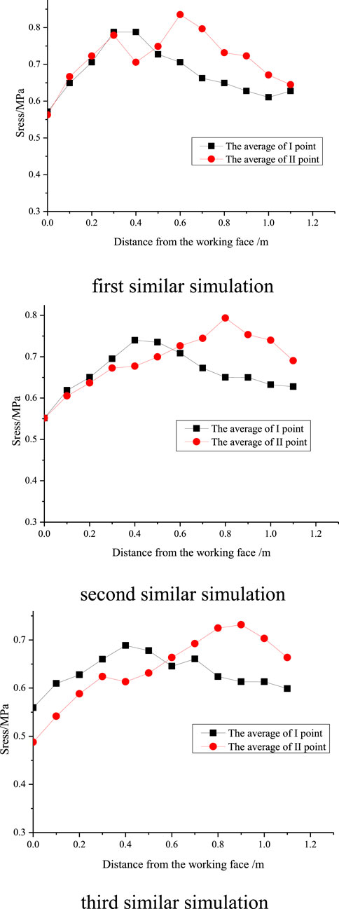
FIGURE 3. Different similar simulation relationship between the mean stress and the distance from the working face.
In the first similar simulation test (top coal thickness of 394 mm), the lower top coal (I observation line) reached a maximum abutment pressure of 0.80 MPa at 0.35 m away from the coal wall, and the upper top coal (II observation line) reached a maximum abutment pressure of 0.83 MPa at 0.60 m away from the coal wall.
In the second similar simulation test (top coal thickness of 460 mm), the lower top coal (I observation line) reached a maximum supporting pressure value of 0.74 MPa at 0.40 m away from the coal wall, and the upper top coal (II observation line) reached a maximum supporting pressure value of 0.78 MPa at 0.80 m away from the coal wall.
In the third similar simulation test (top coal thickness of 526 mm), the lower top coal (I observation line) reached a maximum abutment pressure of 0.69 MPa at 0.40 m away from the coal wall, and the upper top coal (II observation line) reached a maximum abutment pressure of 0.73 MPa at 0.90 m away from the coal wall.
With increasing top coal thickness, the extreme value of the leading supporting pressure decreases gradually, which is directly shown in the above three figures where the pressure distribution line becomes flat. The abutment pressure distribution in the top coal mining of extrathick coal seams has a great influence on the destruction of top coal. The larger the top coal thickness is, the smaller the overall coal breaking effect of the leading abutment pressure. This stress failure feature is the fundamental reason why the top coal crushing degree in the front of the coal face decreases with increasing height from the top plate.
3.3 Vertical displacement results
The vertical displacement test results of the three comparative of similar simulation tests are shown in Figure 4.
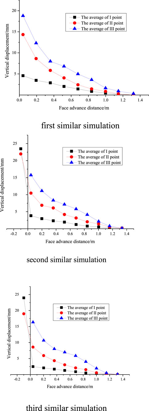
FIGURE 4. Different similar simulation relationship between the mean vertical displacement and the face propulsion.
In the first similar simulation test (top coal thickness of 394 mm), the vertical displacement of the lower top coal (observation line I) was different from that of the middle top coal (observation line II) and the upper top coal (observation line III). The closer the top coal was to the roof, the greater the vertical displacement. Under 0.50 m away from the coal wall, the vertical displacement change trend was basically the same. Over 0.40 m away from the coal wall, the vertical displacement change trend of the lower top coal was obviously different from that of the middle and upper top coal. The vertical displacement increase rate of the lower top coal was not obviously different from that of the former, while the increase rates of the middle and upper top coal were obviously increased. At 0.10 m after mining, the measuring points were destroyed with the destruction of the top coal.
The vertical displacement of the lower top coal (observation line I) was different from that of the middle top coal (observation line II) and upper top coal (observation line III) in the second similar simulation test (top coal thickness of 460 mm). The closer the top coal was to the roof, the greater the vertical displacement. Under 0.40 m away from the coal wall, the vertical displacement change trend was basically the same. Over 0.20 m away from the coal wall, the vertical displacement of the lower top coal was obviously different from that of the middle and upper top coal. The vertical displacement increase rate of the lower top coal was not obviously different from that of the former, but the increase rates of the middle and upper top coal were obviously increased. At 0.10 m after the mining of the working face, the upper top coal measuring point was destroyed with the destruction of top coal. However, the vertical displacement of the lower top coal (23.1 mm) was higher than that of the middle top coal (21.5 mm), indicating that there was a slight separation between the middle and lower top coal.
The vertical displacement of the lower top coal (I observation line) was different from that of the middle top coal (II observation line) and upper top coal (III observation line) in the third similar simulation test (top coal thickness of 526 mm). The closer the top coal was to the roof, the greater the vertical displacement. Under 1.00 m away from the coal wall, the vertical displacement of the top coal was small, with a maximum value of only 1.5 mm. The vertical displacement change trend was basically consistent in the range of 1.00 m–0.40 m away from the coal wall. In the range of 0.20 m–0.04 m away from the coal wall, the vertical displacement of the lower top coal was obviously different from that of the middle and upper top coal. The vertical displacement increase rate of the lower top coal was not obviously different from that of the former, but the increase rates of the middle and upper top coal were obviously increased. At 0.10 m after the mining of the working face, the upper top coal measuring point was destroyed with the destruction of top coal. However, the vertical displacement of the lower top coal increased sharply to 23.6 mm, exceeding that of the middle top coal (the extreme value was 18.5 mm), indicating that there was stratification between the middle and lower top coal.
3.4 Horizontal displacement test results
The horizontal displacement test results of the three comparative similar simulation tests are shown in Figure 5.
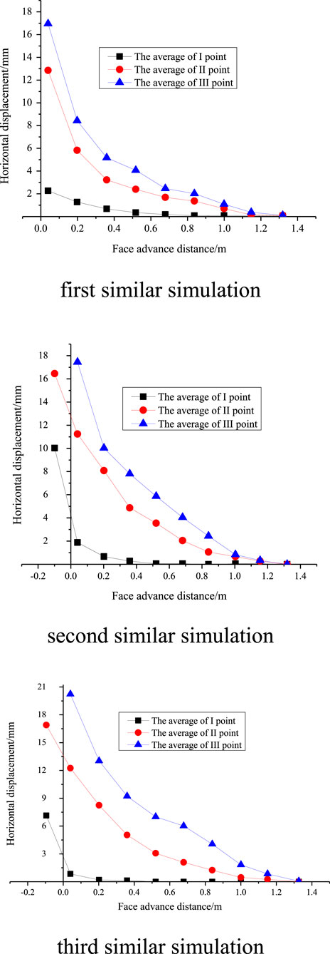
FIGURE 5. Different similar simulation relationship between the mean of horizontal displacement and the face propulsion.
In the first similar simulation test (top coal thickness of 394 mm), the horizontal displacement of the lower top coal (observation line I) was different from that of the middle top coal (observation line II) and the upper top coal (observation line III). The closer the top coal was to the roof, the larger the horizontal displacement. Under 0.40 m away from the coal wall, the vertical displacement change trend was basically the same. Over 0.20 m away from the coal wall, the horizontal displacement of the lower top coal was obviously different from that of the middle and upper top coal. The horizontal displacement increase rate of the lower top coal was small, that of the middle top coal was large, and that of the upper top coal was the largest. Near the coal wall line, the horizontal displacement of the lower top coal increased at a rate similar to that of the upper top coal. At 0.10 m after mining, the measuring points were destroyed with the destruction of the top coal.
The horizontal displacement of the lower top coal (I observation line) was different from that of the middle top coal (II observation line) and upper top coal (III observation line) in the second similar simulation test (top coal thickness of 460 mm). The closer the top coal was to the roof, the larger the horizontal displacement. In general, the vertical displacement of the lower top coal was obviously different from that of the middle and upper top coal. The horizontal displacement of the lower top coal did not change significantly outside 0.20 m in front of the coal wall (the maximum value was 0.5 mm, and the minimum value was -0.1 mm), while the horizontal displacements of the middle and upper top coal were relatively large and changed immediately within 0.80 m in front of the coal wall. At the point where the working face had been mined for nearly 0.10 m, the upper top coal measuring point was destroyed with the destruction of the top coal.
The horizontal displacement of the lower top coal (I observation line) was different from that of the middle top coal (II observation line) and upper top coal (III observation line) in the third similar simulation test (top coal thickness of 526 mm). The closer the top coal was to the roof, the larger the horizontal displacement. In general, the vertical displacement change trend of the lower top coal was obviously different from that of the middle and upper top coal. The horizontal displacement of the lower top coal had no obvious change outside 0.10 m in front of the coal wall (the maximum value was 0.5 mm, and the minimum value was -0.1 mm). However, the horizontal displacement of the top coal in the middle and upper parts was relatively large and changed at 0.90 m in front of the coal wall. At the point where the working face had been mined for nearly 0.10 m, the upper top coal measuring point was destroyed with the destruction of top coal.
4 Numerical simulation of extrathick top coal migration
4.1 Model establishment
Based on the hydrogeological conditions of the working face of the extrathick coal seam and the purpose of the numerical simulation, the rock strata were divided into five geological formations according to their basic properties and parameters, such as siltstone, mudstone, coal seam, conglomerate, and sand-bearing conglomerate. The volume of the numerical model was set at 280 × 216 × 270. The coal seam thicknesses were set at 12, 14, and 16 m. The immediate roof thickness was set at 25 m. The basic roof thickness was set at 115 m, and the floor thickness was set at 70 m. The inclination direction of the working face was set in the Y direction, the strike direction was set in the X direction, the vertical direction of the coal seam was set in the Z direction, and the inclination angle of the coal seam was 14°. The model is shown in Figure 6.
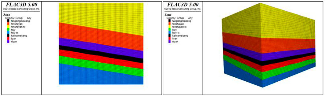
FIGURE 6. Fast-Lagrangian-analysis-of-continua (FLAC) model grid diagram.
The boundary of the numerical model in the x and y directions was given a horizontal constraint, and the boundary strike displacement was set to zero. The bottom boundary of the fixed model, given that the bottom boundary was vertical and the strike displacement was zero, and the lower part of the model Z direction was also given the same constraint. No constraints were imposed on the upper part of the model Z direction, but a certain force was applied, namely, the dead weight stress.
The physical and mechanical parameters of each coal rock layer in the simulation model are shown in Table 3.
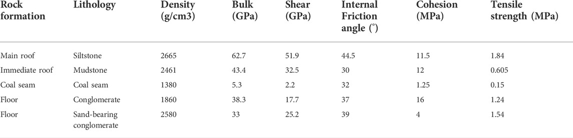
TABLE 3. Coal and rock mechanics parameters.
4.2 Numerical simulation results analysis
To better monitor the extrathick top coal movement, 24 monitoring points were arranged to monitor and record the stress, horizontal displacement, and vertical displacement of the extrathick top coal with coal seam mining, as shown in Figure 7.

FIGURE 7. Schematic diagram of the monitoring point layout.
4.2.1 Top coal stress variation results analysis
In the process of fully mechanized caving mining, the advanced support pressure produced by stoping operation has a certain influence on the top coal release. Therefore, the variation characteristics of the advanced support pressure of the top coal with different layers in the mining process are simulated. To clarify the change rule of top coal advance support pressure in different strata and different directions, and lay the foundation for studying the influence of top coal breakage in different strata on pressure.
The propulsion distance of the working face and the stress of the upper top coal was obtained. A graph of the stress variation with the top coal in the middle is shown in Figure 8.
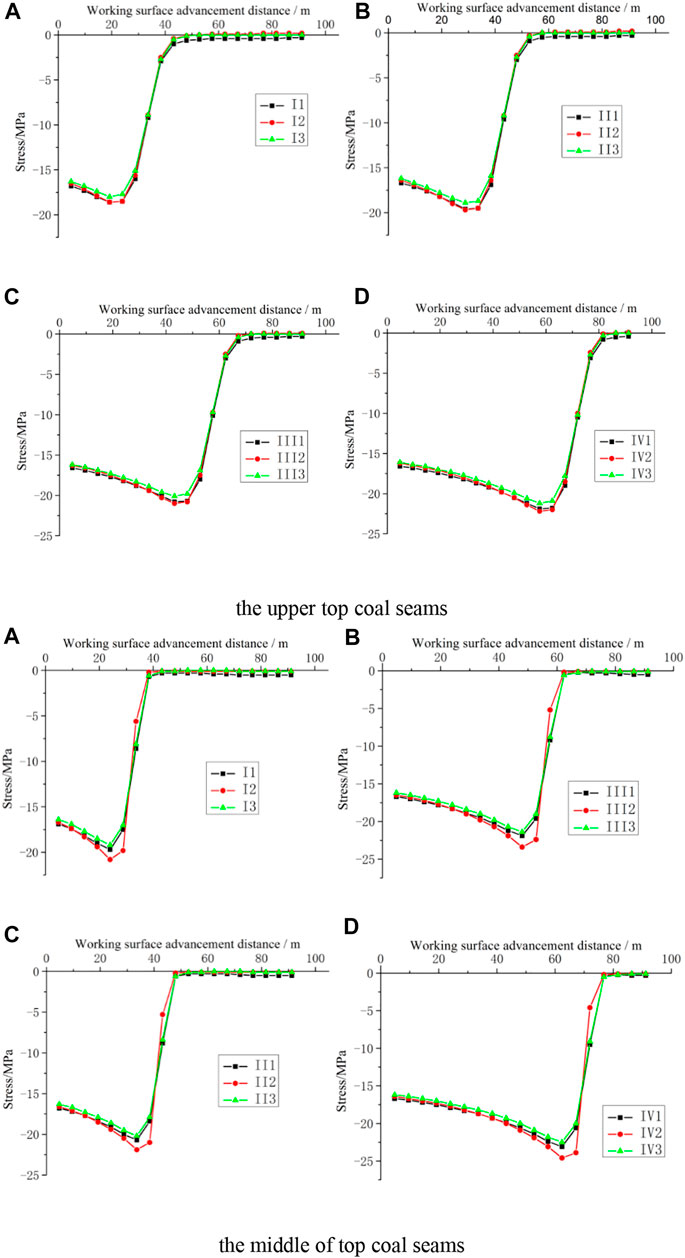
FIGURE 8. Stress change of monitoring points I, II, III, and IV. (A–D) represent the Top coal stress variation on the four detection lines I, II, III and IV.
From Figure 8, it can see that the top coal stress in the upper part of the fully mechanized caving face of the thick coal seam was approximately 20.1 MPa, and the stress in the middle top coal at the same distance in front of the working face was basically the same, approximately 22.5 MPa. Under the influence of the leading support pressure, the stress change in front of the working face increased first and then decreased. Therefore, the working face stress change curve reached a maximum value at the inflexion point in advance and then decreased. The stress in the middle top coal was basically the same at the same distance in front of the working face.
4.2.2 Top coal X-direction displacement results analysis
The stress changes of the upper top coal and the middle top coal in the X direction were recorded, as shown in Figure 9.
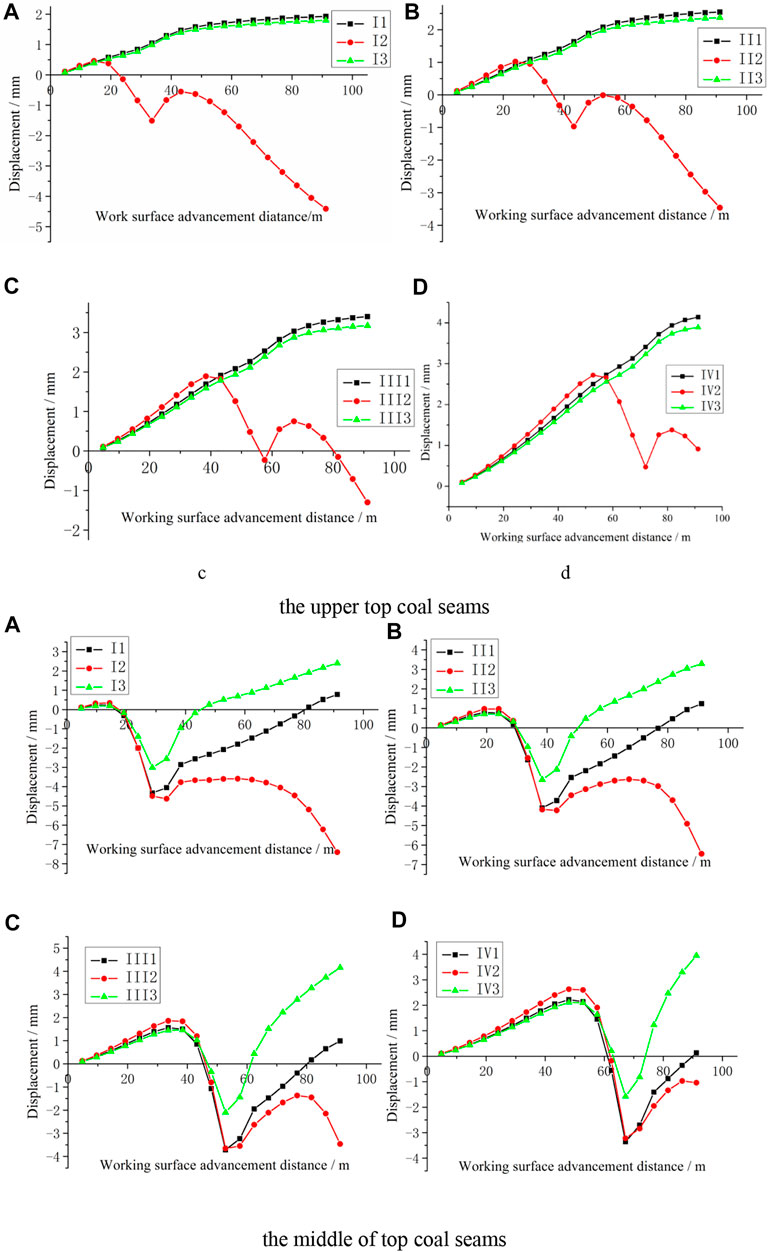
FIGURE 9. Displacement variation in the X direction of the monitoring points I, II, III, and IV. (A–D) represent the Top coal x-direction displacement on the four inspection lines I, II, III and IV, respectively
The top coal displacement in the front face of the fully mechanized caving face in the thick coal seam changed with the same amount of propulsion displacement from the working face, and monitoring point 2 was the most obvious. After analysis and judgment, the top coal in front of the working face undergoes migration and may even break. The top coal displacement is basically consistent with the working face displacement.
Comparing the X-direction displacement of the upper top coal and the middle top coal, we found that the displacements were different. When the distance from the working face was far, the displacement of the middle top coal was higher. With the advancement of the working face, the upper top coal displacement was gradually greater than that of the middle top coal. There were many cracks inside the coal seam. When the coal seam was not affected by mining, it was in the original equilibrium state. With the advancement of the working face, the cantilever top coal was gradually affected by the stress due to the friction between the top coal, the roof, and the upper top. The tensile force of the coal was greater than the tensile force of the middle top coal, which caused the top coal to migrate. When the middle top coal was closer to the working face, the strike displacement became negative, indicating that the middle coal seam changed from the previous three-direction compression to two-direction compression, which caused the middle coal seam to migrate and break.
4.2.3 Top coal Z-direction displacement results analysis
The stress changes of the upper top coal and the middle top coal in the Z direction were recorded, as shown in Figure 10.
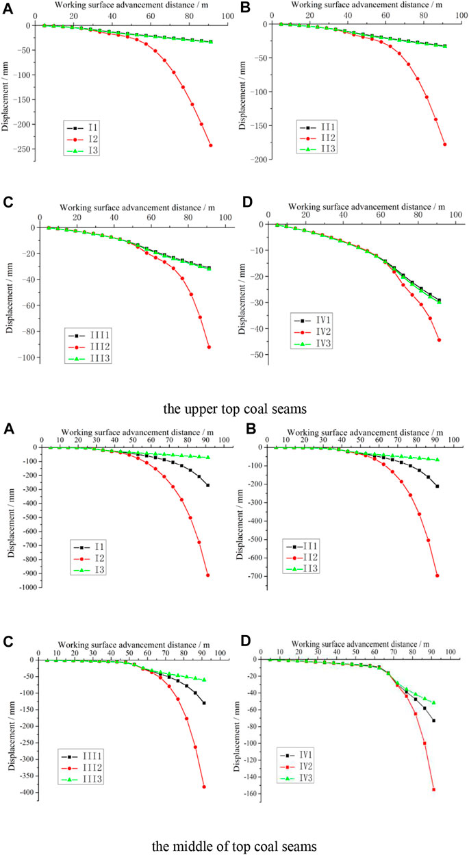
FIGURE 10. Displacement changes in the Z direction of the monitoring points I, II, III, and IV. (A–D) represent the Top coal z-direction displacement on the four inspection lines I, II, III and IV, respectively.
The vertical displacement of the upper top coal in front of the fully mechanized caving face of the thick coal seam was basically the same as the advancing displacement of the working face. When the advancing distance of the working face increased, the increasing displacement rate of monitoring point 2 was continuous, and the increasing range also increased because the top coal collapsed due to damage. Moreover, the vertical displacement of the top coal in the front middle of the fully mechanized caving face of the thick coal seam was basically the same as the advancing displacement of the working face. It can be found that there were some differences between the upper top coal displacement and the middle top coal displacement. The vertical displacement of middle top coal was different from that of the upper top coal. The main reason for this was that the roof rotation caused the middle top coal to migrate; that is, the roof rotation was the main influencing factor of the middle top coal migration.
5 Comparative analysis of the numerical simulation for different top coal thicknesses
In the numerical simulation, comparative experimental analysis was also performed. Compared with the original model, the other two models had an increase or decrease in coal seam thickness by 2 m, i.e., the coal seam thickness was 16 m and 12 m, respectively. The other conditions remained unchanged.
5.1 Numerical simulation of the stress variation for the top coal in different top coal thicknesses
For the corresponding monitoring points of coal seams with different thicknesses, the maximum supporting pressure of the thickened coal seam model in the numerical simulation was the smallest, and the maximum supporting pressure of the thinned coal seam model was the largest. From this, we can conclude that as the top coal thickness increased, the absolute value of the lead support pressure increased gradually. The stress trends of the three thicknesses were basically the same before the working surface advancement of 40 m, and the difference occurred after the propulsion distance was greater than 40 m. The change rate in the stress of the thickened coal seam increased relative to the initial coal seam, while the opposite was true for the thinned coal seam. The three layers of the coal seam stress had a maximum value and an inflection point at a propulsion distance of 50–60 m. The reason for this was that the stress in front of the working face formed a change in the leading support stress. As the working surface advanced, the stress of monitoring point IV gradually increased, reached an initial stress peak, and then gradually decreased to the initial stress. The results are shown in Figure 11.
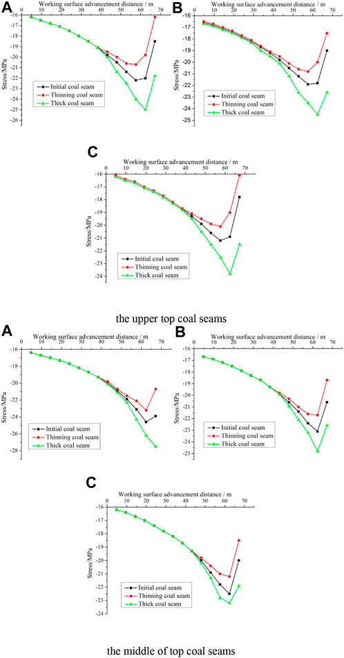
FIGURE 11. Stress change results of the IV1, IV2, and IV3 points of the middle coal. (A–C) respectively represent the Stress variation of top coal at different layers at monitoring points 1, 2 and 3 on No. IV detection line.
5.2 Numerical simulation of the top coal displacement trends with different top coal thicknesses
For different coal thicknesses, the displacement of the upper top coal increased with the advancement of the working face, and the increasing rate was basically the same from 0 to 45 m. This change in the middle top coal was similar to that in the upper top coal. However, above 45 m, the thinner the coal seam thickness at the 1st monitoring point and the 3 monitoring points in the upper top coal was, the faster the displacement rate. For the monitoring point displacement, as the working face advanced, the larger the thickness of the coal seam was, and the earlier the displacement reduced, which indicated that the top coal was more affected by the tensile stress, making it more likely to migrate. The results of monitoring points 1, 2, and 3 in the middle top coal were different from those in the upper top coal. The middle top coal began to change after the working face was pushed for 40 m, and the result of the change was not only reduced but also increased in the opposite direction, and the increase rate was greater than the initial rate. This is because after the bottom coal seam was excavated, the upper part of the upper coal seam was suspended at the other end to form a simply supported beam structure. This mechanical action caused the middle top coal to move downward, and the simple supported beam structure caused the central coal seam to form an arch structure in the opposite direction. The results are shown in Figure 12.
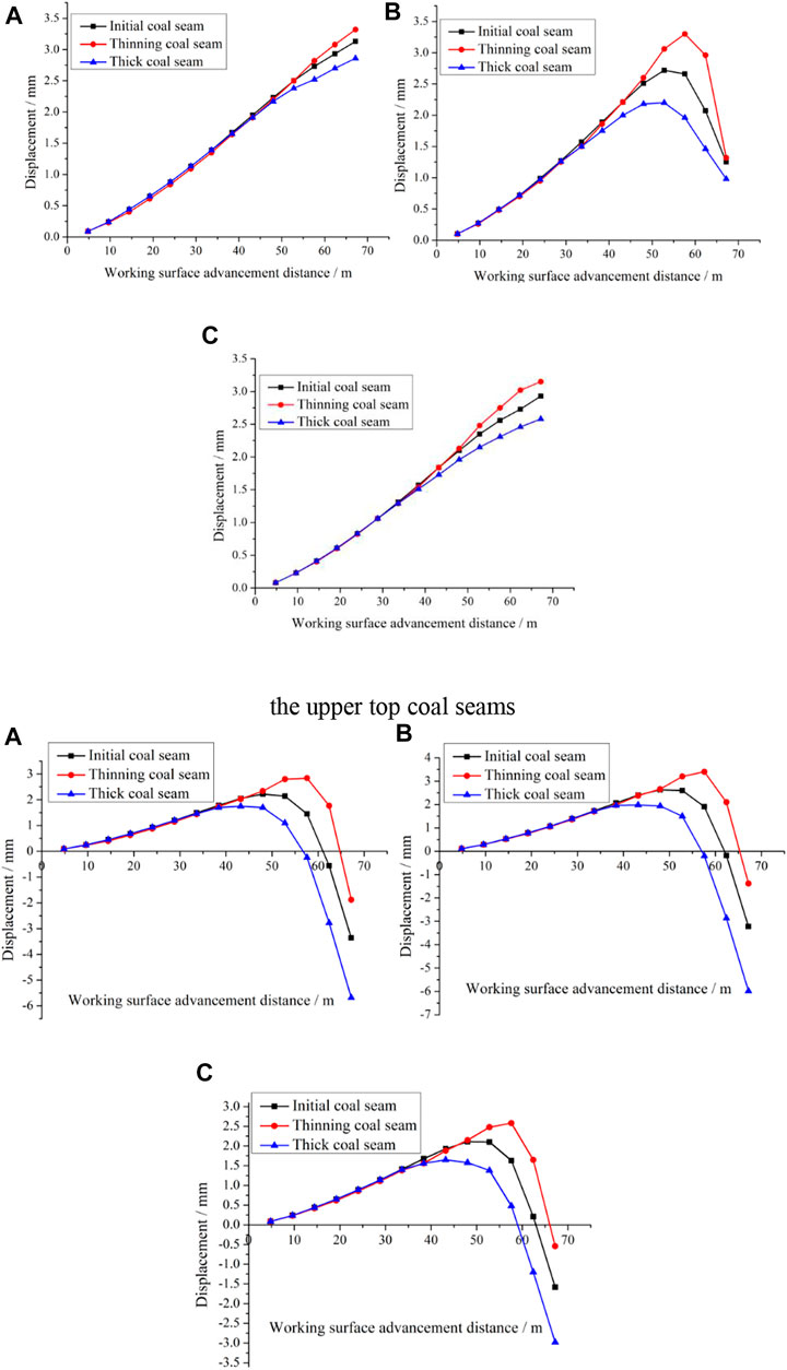
FIGURE 12. Comparison of the displacement for the IV1, IV2, and IV3 points. (A–C) represent the top coal displacement trends of different layers at monitoring points 1, 2 and 3 on test line IV, respectively
5.3 Numerical simulation of the top coal vertical displacement results with different top coal thicknesses
For different coal thicknesses, whether it was the upper or middle top coal, the vertical displacement became increasingly larger as the working surface advanced. In the early stage of advancement, the vertical displacement increase rates for the three coal seams were similar. That is, as the coal seam thickness increased, the vertical displacement change rate gradually increased at the position corresponding to the monitoring point in front of the working surface. Moreover, the vertical displacement of the middle coal seam suddenly increased after the working face advanced 60 m, and the change rate suddenly increased. Because the coal seam of the middle top coal was excavated as the working surface advanced, the lower part of the middle top coal became a goaf, drastically changing the vertical displacement of the middle top coal. This trend also occurred for the vertical displacement of the upper coal seam but occurred later than for the middle coal seam. The results are shown in Figure 13.
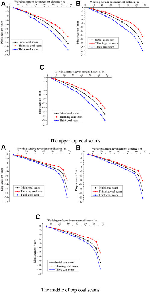
FIGURE 13. Comparison of the vertical displacement for the IV1, IV2, and IV3 points. (A–C) represent the top coal vertical displacement results of different layers of top coal at monitoring points 1, 2 and 3 on test line IV, respectively.
6 Field test
The field test mainly focused on the presupporting pressure monitoring of the full-height comprehensive mechanized top coal caving face system in the ultrathick coal seam, the deep coal point displacement observation of the top coal, and the roadway deformation observation and studied the extrathick top coal crushing and migration.
6.1 Test content, method, and device
6.1.1 Top coal stress field test
KBSII is a name for measuring borehole stress instruments. The top coal stress field test was observed using a KBSII-type borehole stress meter. Four observation lines were arranged from the bottom to the top of the working face and the gas discharge lane. Observation lines I and II had a depth of 25 m, and observation lines III and IV had a depth of 12 m. The observation lines were arranged with a spacing of 5 m. Figure 14 is schematic views showing the layout of the embedded KBS II-type borehole stress gauge.
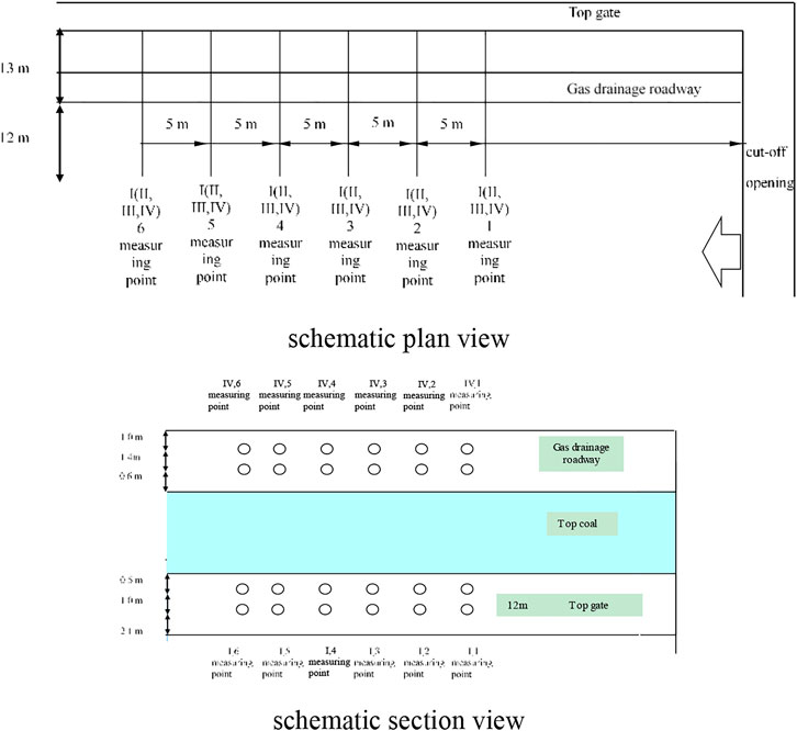
FIGURE 14. Schematic views showing the layout of the embedded KBS II-type borehole stress gauge.
6.1.2 Top coal displacement field test
The top coal displacement field test was observed by the deep base (drilling) hole base point tracking method, and the observation instrument was a self-designed deep-hole multipoint displacement meter. A schematic diagram of the deep base point arrangement is shown in Figure 15.
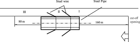
FIGURE 15. Arrangement of sublevel coal deep-hole base stations.
To facilitate the displacement and observation of the top coal in front of large-scale control work, three stations were arranged in the upper plane along the propulsion direction of the working plane, with one drill hole per station, and the parameters were all the same. Four anchored deep foundation points were installed in each borehole. The first base point was 0.7 m deep into the roof rock stratum of the coal seam. The second base point was located in the top coal 6 m above the top of the roadway. The third base point was located in the top coal 3 m above the top of the roadway. The fourth base point was located in the top coal 1 m above the top of the roadway, as shown in Figure 14. The deep base drilling parameters are shown that Hole depth is 28 m.Advancement direction angle is 135°. Elevation angle is 45°.Floor level to orifice height is 18 m.
6.2 Field test results
6.2.1 Stress results
To facilitate further analysis and research of the content reflected by the data, the interpolation curve method was used to obtain the relationship between the stress reading of each measuring point and the coal wall of the measuring point from the working face. The results are shown in Figure 16.
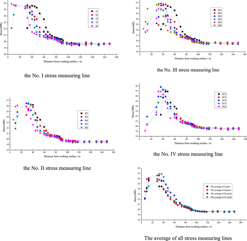
FIGURE 16. Relationship between the stress and the distance of the different stress measuring lines.
Figure 16 show that the frontal stress of the fully mechanized caving face for the extrathick coal seam was approximately 19.6 MPa, and the stress of the top coal pressure of the working face was approximately 90 m in front of the working face. It increased rapidly within 40–50 m, reaching a maximum value of approximately 26 MPa 10–40 m in front of the working surface, and the dynamic pressure coefficient of the working surface was approximately 1.3. Figure 17 indicates that the stress in the top coal at the same distance from the working face differed: the upper top coal stress was larger, and the lower top coal stress was smaller, such as 35 m in front of the working face, where the average of the No. I line was 25.2. The mean value of lines I and II was 22.2 MPa, the average value of line III was 23.8 MPa, and the mean value of line IV was 22.6 MPa.
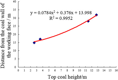
FIGURE 17. Relationship between the maximum abutment pressure and distance to face.
According to Figure 17, both the field measurement and the traditional theoretical calculation of the peak stress were greater than the uniaxial compressive strength of the coal body, which means that the top coal at the peak point was not in a uniaxial compression state but in a two- or three-axis force state. Therefore, the top coal stress environment is crucial for the destruction of top coal. Through the stress environment analysis, we can conclude that, in the vertical direction, the top coal is above the coal body to be cut by the lower coal mining machine, which is followed by the direct top and the old top, and the longitudinal mechanical system is the top plate (Direct top, old top) - top coal - bottom coal to be cut - bottom plate.
6.2.2 Displacement results
We can see from Figure 18 that the starting points of the top coal displacement in the extrathick coal seam measured by stations I, II, and III were approximately 73, 70, and 77 m in front of the working surface, respectively. The arithmetic average of the similar measuring points of the station were obtained. The starting point of the average top coal displacement was approximately 74 m in front of the working face, as shown in Figure 18. In the range of approximately 74 m–55 m, the base point displacement of the lower top coal at a depth of 1 m was basically 0 mm, while the base point displacement at 3 and 6 m depths gradually increased, and the base point of the deep top rock began to move from approximately 85 m in front of the working surface. At 55 m in front of the working face, the cumulative displacement reached 13 mm. With the advancement of the working surface, the deep base point displacement increased sharply, but the difference in the base points of different layers was larger, as shown in Figure 18. At the coal wall, the top coal in the lower base of Classes 3 and 4 was also fully compacted. The deep base point of the deep rock in the top rock was 10 m adjacent to the top of the working face, the top coal was gradually separated from the top rock, and the top rock was broken in the front 4 m. Because the coal was soft and the thickness was large, the top coal caving angle was approximately 112.6°, and the top coal was stepped and broken.
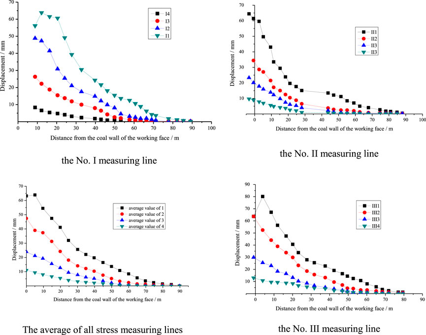
FIGURE 18. Relationship between the sublevel coal displacement and the distance of the different measuring lines.
Thus, the following deformation characteristics can be obtained: The initial movement point of the top coal is approximately 74 m in front of the working face. The higher the horizon is, the farther the distance between the initial movement point and the coal wall is.
With decreasing relative distance of the working face, the top coal deformation increases gradually. According to the measured deformation data, the top coal deformation in front of the working face can be divided into three areas: the initial deformation area, stable deformation area and sharp deformation area.
From the initial movement point of the top coal to the area 25 m in front of the coal wall, the average top coal deformation velocity was 1 mm/d, and the total deformation was 5–25 mm. The deformation in this area was mainly due to the vertical displacement formed by the compression and closure of near-horizontal primary fractures. This area was called the initial top coal deformation zone. In the area of 10–25 m in front of the working face, the top coal deformation increased rapidly, the average deformation velocity was 7 mm/d, the deformation was relatively stable, and the maximum deformation reached 48 mm. The deformation in this area was mainly due to the vertical displacement of coal, which was similar to the linear elastic compression deformation. This area was called the stable top coal deformation area. In the working face in front of the 10 m area, the upper level of top coal deformation increased sharply, the maximum deformation rate was 13 mm/d, and the maximum deformation was reached. The main characteristic was due to upper top coal deformation caused by peak pressure after fracturing, slippage in the goaf below the direction, the displacement caused by a sharp change, and a sharp area called the top coal deformation area.
6.2.3 Roadway deformation results
During the test, station III was damaged, and the remaining results are shown in Table 4.
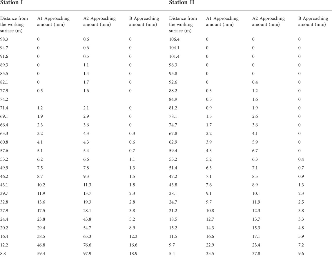
TABLE 4. In situ displacement measurement results in the roadway.
It can be seen from the Origin fitting in Figure 19 that the displacements of the top and bottom plates of the two stations were significantly larger than those of the two gangs; the roadway 90 m in front of the working surface began to deform; and the top and bottom plates were moved within 30–90 m of the working surface. The near speed and the two-way approaching speed were basically constant (the top and bottom plates moved closer to the average speed and stabilized at 0.6 mm/d, and the average speed of the two gangs was stable at 0.1 mm/d), while at 25–30 m, the two shifted. The near speed increased, and the approaching speed was basically constant in the range of 15–25 m (the top and bottom plates moved closer to the average speed and stabilized at 3 mm/d, and the average speed of the two gangs was stable at 1 mm/d) within 15 m of the working face.
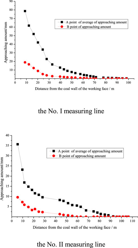
FIGURE 19. Relationship between the displacement and the distance of the different measuring lines.
6.3 Summary results of the field test
Based on the above observation results of the working face leading support pressure, top coal stress, displacement, and roadway deformation in the extrathick coal seam, we conclude that, due to the large thickness of the primary mining, the original rock stress at 90 m in front of the working face was destroyed, and the leading support pressure gradually increased. The top coal was completely in a three-direction stress state, and the advance bearing pressure increased slightly. The obvious top coal deformation appeared at approximately 74 m in front of the working face, which reflects the “hysteresis effect” of the top coal deformation. With the shortening of the distance from the working face, the advance bearing pressure gradually increased and rapidly increased within 40–50 m of the working face. However, the top coal deformation from the initial movement point to the region 25 m from the front of the coal wall had a small average deformation velocity. The displacement was mainly caused by the compression and closure of the near-horizontal primary fractures, which also reflects the “hysteresis effect” of top coal deformation. In the area 10–25 m in front of the working face, the top coal was close to or affected by the peak of the leading supporting pressure, but due to the “hysteresis effect” of top coal deformation, the deformation still reflected the top coal movement caused by the rapid pressure growth in the peak area of the supporting pressure. The main performance was that the displacement increased rapidly, and the deformation was relatively stable and mainly due to the vertical displacement formed by the approximate linear elastic compression deformation of the coal mass. Finally, the leading bearing pressure of the working face reached a maximum value within the range of 10–40 m from the working face, resulting in the fracturing and shearing of the upper top coal and the beginning of fracturing. Therefore, in the area 10 m ahead of the working face, the horizontal deformation of the upper top coal increased sharply, and the total deformation reached a maximum value. The deformation in this area was mainly characterized by the upper top coal sliding to the lower direction of the goaf due to upper top coal fracturing under peak pressure, resulting in a change in the overall displacement of the deep base point and thus a sharp change in displacement. In general, because the top coal thickness of this working face was large, the dynamic pressure coefficient (approximately 1.3) was smaller than that of the general thick coal seam, and the top coal displacement increased relatively gently in the region of 10–25 m in front of the working face.
Moreover, both the extrathick coal seam stress and displacement showed obvious horizon characteristics. The top coal seam stress and displacement were large, while the bottom coal seam stress and displacement were small. Compared with the top coal displacement, the “hysteresis effect” of roadway deformation was not obvious and was basically synchronous with the change in stress. We think that the reason for this is mainly because the stresses of the lane edge and deep coal caving are different: deep top coal is completely in the three-way stress state, the lane edge coal behaves according to its interval distance on the surface of the roadway and the support form, and the support quality can be in three different stress states, including two-way and one-way, causing full space deformation.
7 Conclusion
From what has been discussed above, according to the characteristics of migration and failure of top coal in extra-thick coal seam, the damage, failure and deformation process of top coal can be divided into initial compression and plastic deformation zone, intense compression and failure zone, short beam rotation and support action zone. In the vertical direction of the coal seam in the range of roof control, according to the characteristics of deformation and crushing of the top coal in the extra-thick fully mechanized caving face, it can be successively divided into roof failure layer, short beam structure layer and support failure layer from top to bottom.
When the coal seam thickness is constant, the coal bodies at different distances in front of the working face are different in the coal seam due to the influence of the leading bearing pressure. The upper top coal stress is small, and the middle top coal stress is large. When the coal seam thickness is constant, in front of the working face, the upper top coal vertical displacement is greater than the middle top coal vertical displacement due to the top plate rotation.
For different coal thicknesses, whether it is the upper top coal or the middle top coal, in front of the advancing working face, the top coal displacement has an increasing trend. However, with the advancement of the working face, the top coal is subjected to tensile stress, and it changes from the original three-direction force to the two-direction force, causing the top coal to undergo large migration or even fracture.
The failure of the middle and lower top coal is the key to the full failure of the whole top coal. The key to the failure of lower top coal is the function of support back and forth. The complete discharge of the upper top depends on the integrity of the simply supported beam formed locally by the middle top coal. Before the failure of simply supported beam, the upper top coal is affected by the support force, and its displacement, deformation and failure degree are very small. When the simply-supported beam formed by the middle top coal is damaged by stress, the maximum displacement and failure degree of the upper top coal are larger than those of the other layers.
Data availability statement
The original contributions presented in the study are included in the article/supplementary material, further inquiries can be directed to the corresponding author.
Author contributions
Author HN is responsible for funding and improvement of the paper. Author SW is responsible for writing the first draft of the paper.
Funding
This work was financially supported by Experimental study on the performance and instability mechanism of GFRP anchor in coal roadway with back-filling by bottom expanding (51974106); The model and method for coordinated intelligent coal caving process in ultrathick coal seam mining (2018YFC0604502); Xinjiang collaborative innovation project (2017E0292); Dynamic load impact effect and mechanism of fully mechanized top coal caving face with shallow and thick coal seams based on different mining and drawing ratios (182300410120); Research fund for the doctoral program of higher education of HPU (RFDP) (660207/018); Scientific and technological research projects of Henan Province (182102310020), the research fund of the State Key Laboratory For Geomechanics And Deep Underground Engineering, China University of Mining & Technology (SKLGDUEK 2004), the research fund of the Key Laboratory Of Western Mine Exploitation And Hazard Prevention, Ministry of education (SKLCRKF 1902), the research fund of Henan Key Laboratory For Green And Efficient Mining & Comprehensive Utilization Of Mineral Resources (Henan Polytechnic University) (KCF201801).
Conflict of interest
The authors declare that the research was conducted in the absence of any commercial or financial relationships that could be construed as a potential conflict of interest.
Publisher’s note
All claims expressed in this article are solely those of the authors and do not necessarily represent those of their affiliated organizations, or those of the publisher, the editors and the reviewers. Any product that may be evaluated in this article, or claim that may be made by its manufacturer, is not guaranteed or endorsed by the publisher.
References
Bai, Q. S., Tu, S. H., Wang, F. T., and Zhang, C. (2017). Field and numerical investigations of gateroad system failure induced by hard roofs in a longwall top coal caving face. Int. J. Coal Geol. 173, 176–199. doi:10.1016/j.coal.2017.02.015
Bondarenko, Yu.V., Makecv, A. Yu, Zhurek, P., and Klega, L. (1993). Technology of coal extraction from steep seam in the Ostrava-Karvina basin. Ugol Ukralny 4 (3), 45–48.
Cheng, G., Ma, T., Tang, C., Liu, H., and Wang, S. (2017). A zoning model for coal mining-induced strata movement based on microseismic monitoring. Int. J. Rock Mech. Min. Sci. 94, 123–138. doi:10.1016/j.ijrmms.2017.03.001
Duan, L. Q., Dong, L., and Ma, L. J. (2018). Experimental study of acoustic emission characteristics of foamed concrete under uniaxial compression. J. China Univ. Min. Technol. 47 (4), 742–747.
Feng, Y. F. (2014). Research on key technologies of fully mechanized caving mining with special thick coal seam. China: University of Mining and Technology.
Guo, W., Tan, Y., and Bai, E. (2017). Top coal caving mining technique in thick coal seam beneath the Earth dam. Int. J. Min. Sci. Technol. 27 (1), 165–170. doi:10.1016/j.ijmst.2016.11.005
Habib, A., and Brett, A. P. (2010). Stress analysis of longwall top-coal caving. Int. J. Rock Mech. Min. Sci. 47 (1), 30–41. doi:10.1016/j.ijrmms.2009.07.004
Huang, Z. Z., Mao, D. B., and Liu, Q. J. (2015). Study on the characteristics of ultra-thick top coal migration in large mining height fully mechanized caving. China coal. 41 (11), 41–43+63.
Jiang, J. B., Chen, D. Y., and Li, Z. (2016). Numerical simulation study on the surrounding rock migration law of fully mechanized top coal caving face. Inn. Mong. Coal Econ. 10, 115–116.
Kong, B., Li, Z., Wang, E., Lu, W., Chen, L., and Qi, G. (2018). An experimental study for characterization the process of coal oxidation and spontaneous combustion by electromagnetic radiation technique. Process Saf. Environ. Prot. 119, 285–294. doi:10.1016/j.psep.2018.08.002
Lan, Y. W., Gao, R., Yu, B., and Meng, X. (2018). In situ studies on the characteristics of strata structures and behaviors in mining of a thick coal seam with hard roofs. Energies 11 (9), 2470. doi:10.3390/en11092470
Li, C. (2013). Study on top coal fracture mechanism and recovery rate of fully mechanized caving face in Gongwusu Mine. Hohhot: Inner Mongolia University of Science and Technology.
Li, P. (2015). Study on top coal migration and ore pressure behavior in fully mechanized caving face of thick coal seam. China: University of Mining and Technology.
Li, X. L., Chen, S. J., Liu, S. M., and Li, Z. h. (2021a). AE waveform characteristics of rock mass under uniaxial loading based on Hilbert-Huang transform. J. Cent. South Univ. 28 (6), 1843–1856. doi:10.1007/s11771-021-4734-6
Li, X. L., Chen, S. J., Wang, S., Zhao, M., and Liu, H. (2021b). Study on in situ stress distribution law of the deep mine taking Linyi Mining area as an example. Adv. Mater. Sci. Eng. 9 (4), 5594181–5594211. doi:10.1155/2021/5594181
Liu, H. Y., Zhang, B. Y., Li, X. L., Liu, C., Wang, C., Wang, F., et al. (2022). Research on roof damage mechanism and control technology of gob-side entry retaining under close distance gob. Eng. Fail. Anal. 138 (5), 106331–112022. doi:10.1016/j.engfailanal.2022.106331
Liu, S. M., Li, X. L., Wang, D. K., and Zhang, D. (2020). Investigations on the mechanism of the microstructural evolution of different coal ranks under liquid nitrogen cold soaking. Energy Sources Part A Recovery Util. Environ. Eff. 2020, 1–17. doi:10.1080/15567036.2020.1841856
Liu, S. M. (2018). Study on the movement law of top coal and its overlying strata in the first mining face Of west block of zhao Zhuang two well. Taiyuan: Taiyuan University of Technology.
Liu, X., Song, D., He, X., Wang, Z., Zeng, M., and Deng, K. (2019). Nanopore structure of deep-burial coals explored by AFM. Fuel 246, 9–17. doi:10.1016/j.fuel.2019.02.090
Lv, H. Y., Wang, Z. H., and Tang, Y. S. (2019). Experimental study on the law of top coal fracture and migration in fully mechanized caving mining under special thick coal seams. Chin. J. Rock Mech. Eng. 38 (03), 476–486.
Ma, F. (2016). Study on the law of top coal activity and optimization of process parameters in the fully mechanized top coal caving face of Shenghua Coal Industry. Taiyuan: University of Technology.
Ma, J. H., Hou, C., and Chen, Y. B. (2016). Numerical simulation of top coal movement law in fully mechanized caving face. Coal Mine Saf. 47 (08), 216–218.
Mahdi, S., and Charlie, C. L. (2012). Numerical modelling of longwall mining and stability analysis of the gates in a coal mine. Int. J. Rock Mech. Min. Sci. 51 (1), 24–34. doi:10.1016/j.ijrmms.2012.02.002
Mao, D. B., and Yao, J. G. (2010). Study on the adaptability of large mining height fully mechanized caving mining. J. China Coal Soc. 35 (11), 1837–1841.
Meng, X. R., Chen, H. B., and Hu, B. B. (2003). Top-coal move-ment theory of top-coal mining and establishment of its mathemati-cal model. Coal Eng. 10, 32–34.
Nan, H., Wang, Q. H., and Zhao, X. W. (2010). Study on failure mechanism of fully mechanized top coal caving. Beijing: Coal Industry Press.
Nan, H., Zhang, G. Y., and Chen, L. W. (2005). Study on fully mechanized caving technology in extra-thick coal seams. Beijing: Development and innovation of fully mechanized top coal caving, 202–208.
Qian, M. G., Shi, P. W., and Xu, J. L. (2010). Pressure and rock formation control on mine. Beijing: China university of mining and technology press.
S Bai, Q., and H Tu, S. (2020). Numerical observations of the failure of a laminated and jointed roof and the effective of different support schemes a case study. Environ. Earth Sci. 2020 (79), 202. doi:10.1007/s12665-020-08935-2
Schgal, V. K., and Coalfields Kumar, A. (1992). Thick and steep seam mining in North EastrenInternational symposium on thick seam mining:problem and issues(ISTS’92). New Delhi: Oxford IBH Publishing Co, 457–469.
Si, G., Jamnikar, S., Lazar, J., Shi, J. Q., Durucan, S., Korre, A., et al. (2015). Monitoring and modelling of gas dynamics in multi-level longwall top coal caving of ultra-thick coal seams, part I: Borehole measurements and a conceptual model for gas emission zones. Int. J. Coal Geol. 144-145, 98–110. doi:10.1016/j.coal.2015.04.008
Szurgacz, D., and Brodny, J. (2018). Analysis of rock mass dynamic impact influence on the operation of a powered roof support control system. E3S Web Conf. 29, 00006. doi:10.1051/e3sconf/20182900006
Tan, Y. L., Zhao, T. B., and Xiao, Y. X. (2010). Quantitative prop support estimation and remote monitor early warning for hard roof weighting at the Muchengjian Mine in China. Can. Geotech. J. 47, 947–954. doi:10.1139/t10-009
Unver, B., and Yasitli, N. E. (2006). Modelling of strata movement with a special reference to caving mechanism in thick seam coal mining. Int. J. Coal Geol. 2006 (66), 227–252. doi:10.1016/j.coal.2005.05.008
Vakili, A., and Hebblewhite, B. (2010). A new cavability assessment criterion for longwall top-coal caving. Int. J. Rock Mech. Min. Sci. 47 (8), 1 317–321 329. doi:10.1016/j.ijrmms.2010.08.010
Wang, E. Y., Liu, X. F., and He, X. Q. (2018). Acoustic emission and electromagnetic radiation synchronized monitoring technology and early-warning application for coal and rock dynamic disaster. J. China Univ. Min. Technol. 47 (5), 953–959.
Wang, H. S. (2016). Study on gas migration law and application of control technology in fully mechanized top coal caving. Beijing: University of Science and Technology.
Wang, J. C. (2018). Engineering practice and theoretical progress of top-coal caving mining technology in China. J. China Coal Soc. 43 (1), 43–51.
Wang, J. H. (2006). Current status and development trend of fully mechanized mining technology and equipment in China. Coal Sci. Technol. 34 (1), 4–7.
Wang, J. (2008). Study on the law of coal and rock caving and the parameters of coal caving in fully mechanized caving mining in thick seam. China: University of Mining and Technology.
Wang, J., Yu, B., Kang, H., Wang, G., Mao, D., Liang, Y., et al. (2015). Key technologies and equipment for a fully mechanized top-coal caving operation with a large mining height at ultra-thick coal seams. Int. J. Coal Sci. Technol. 2 (2), 97–161. doi:10.1007/s40789-015-0071-4
Wang, W., Zhao, G., Lou, G., and Wang, S. (2019). Height of fractured zone inside overlying strata under high-intensity mining in China. Int. J. Min. Sci. Technol. 29 (1), 45–49. doi:10.1016/j.ijmst.2018.11.012
Wu, W. H. (2017). Research on overburden migration law of pillar-type caving mining in steep inclined thick coal seam. Inn. Mong. Coal Econ. Z1, 124–126.
Xia, H. C., Yu, B., and Li, W. (2017). Study on the coal migration law of fully mechanized top coal caving in extra-thick medium-hard coal seam in Datong mining area. Coal Technol. 36 (03), 35–38.
Xie, H., and Zhou, H. W. (2008). Application of fractal theory to top-coal caving. Chaos Solit. Fractals 36 (4), 797–807. doi:10.1016/j.chaos.2006.07.024
Yang, R. S., Zhu, Y. L., Zhu, X. L., Dongming, G., and Guihe, L. (2011). Discussions on some security mining problems of fully-mechanized top coal mining in “three soft” large inclined angle working face. Procedia Eng. 26, 1144–1149. doi:10.1016/j.proeng.2011.11.2284
Yu, J., Yao, W., Duan, K., Liu, X., and Zhu, Y. (2020). Experimental study and discrete element method modeling of compression and permeability behaviors of weakly anisotropic sandstones. Int. J. Rock Mech. Min. Sci. 104, 104437. doi:10.1016/j.ijrmms.2020.104437
Yu, J., Liu, G. Y., Cai, Y. Y., Zhou, J., Liu, S., and Tu, B. (2020). Time-dependent deformation mechanism for swelling soft-rock tunnels in coal mines and its mathematical deduction. Int. J. Geomech. 20 (3), 04019186. doi:10.1061/(asce)gm.1943-5622.0001594
Zhai, X. X., Li, S. M., and Du, J. P. (2009). Movement rule of top-coal with sublevel caving in bottom-slice. J. Min-ing Saf. Eng. 26 (3), 82–86.
Zhai, X. X., Zhao, X. F., and Tu, X. Z. (2019). Study on deformation and movement law of overlying thick conglomerate layer in top coal caving. J. henan Polytech. Univ. Nat. Sci. Ed. 38 (03), 16–23.
Zhang, C., Liu, J. B., X Zhao, Y., Han, P., and Zhang, L. (2020). Numerical simulation of broken coal strength influence on compaction characteristics in goaf. Nat. Resour. Res. 29 (4), 2495–2511. doi:10.1007/s11053-019-09613-2
Zhang, C., and Zhang, L. (2019). Permeability characteristics of broken coal and rock under cyclic loading and unloading. Nat. Resour. Res. 28 (3), 1055–1069. doi:10.1007/s11053-018-9436-x
Zhang, J. X., Li, B. Y., Zhou, N., and Zhang, Q. (2016). Application of solid backfilling to reduce hard-roof caving and longwall coal face burst potential. Int. J. Rock Mech. Min. Sci. (1997). 88, 197–205. doi:10.1016/j.ijrmms.2016.07.025
Zheng, Z. T., Xu, Y., Li, D. S., and Dong, J. H. (2015). Numerical analysis and experimental study of hard roofs in fully mechanized mining faces under sleeve fracturing. Minerals 5, 758–777. doi:10.3390/min5040523
Zhong, T. (2015). Structural characteristics of coal raft flow field and top coal loss law in fully mechanized top coal caving mining in special thick seam. China: University of Mining and Technology.
Zhou, X. M., Wang, S., Li, X. L., Meng, J., Li, Z., Zhang, L., et al. (2022). Research on theory and technology of floor heave control in semicoal rock roadway: Taking longhu coal mine in Qitaihe mining area as an Example. Lithosphere 2022 (11), 3810988. doi:10.2113/2022/3810988
Zhu, L. P., and Yan, S. H. (2011). Numerical simulation of top-coal move-ment rule in fully-mechanized caving mining with large mining height. Coal Min. Technol. 16 (1), 11–14.
Zhu, X. Y. (2017). Study on the law of top coal and roof movement in fully mechanized caving mining in “three softs” extra-thick coal seams. Henan Polytechnic University.
Keywords: top coal caving, migration, stress, displacement, top coal thickness, similar simulation test, field test
Citation: Nan H and Wang S (2022) Migration law of different top coal thicknesses in top coal caving. Front. Earth Sci. 10:999979. doi: 10.3389/feart.2022.999979
Received: 21 July 2022; Accepted: 08 August 2022;
Published: 12 September 2022.
Edited by:
Junjian Zhang, Shandong University of Science and Technology, ChinaReviewed by:
Xuelong Li, Shandong University of Science and Technology, ChinaYuliang Zhou, China University of Mining and Technology, China
Copyright © 2022 Nan and Wang. This is an open-access article distributed under the terms of the Creative Commons Attribution License (CC BY). The use, distribution or reproduction in other forums is permitted, provided the original author(s) and the copyright owner(s) are credited and that the original publication in this journal is cited, in accordance with accepted academic practice. No use, distribution or reproduction is permitted which does not comply with these terms.
*Correspondence: Shuai Wang, d3MxNTAzNjUxMjk0N0AxNjMuY29t