
95% of researchers rate our articles as excellent or good
Learn more about the work of our research integrity team to safeguard the quality of each article we publish.
Find out more
ORIGINAL RESEARCH article
Front. Earth Sci. , 10 January 2023
Sec. Environmental Informatics and Remote Sensing
Volume 10 - 2022 | https://doi.org/10.3389/feart.2022.998717
This article is part of the Research Topic Advances and Applications of Artificial Intelligence and Numerical Simulation in Risk Emergency Management and Treatment View all 22 articles
 Lin Zhang1
 Yuangui Pan2*
 Kezhu Chen3*
 Guoqiang Zheng3
 Yang Gao4
 Peng Chen1Guoxiang Zhong1Panfeng Chen1Fengshou Xu1Yong Zhang1Guangyu Nan1Haobo Xue1Tingshuai Wang1Peng Zhao1
 Feng Lu4
Several engineering practices have shown that the excavation of shallow-buried tunnels beneath major roads, as well as the selection of appropriate engineering measures and construction methods, has a significant impact on road surface settlement. Therefore, field monitoring and numerical simulation are adopted in this study to analyze the effect of the cross diaphragm (CRD) excavation method on surface settlement for the under-construction Yüan 1 railroad tunnel. The findings show that during the excavation of the four divisions of the CRD excavation method for shallow-buried tunnels, the amount of surface settlement caused by the excavation of part 1 accounts for 40% of the total surface settlement, followed by the excavation of part 3, accounting for 30% of the total surface settlement, and the difference between the excavation of parts 2 and 4 is insignificant, with part 2 slightly larger than part 4. The main influence of the CRD method on surface settlement for shallow-buried tunnels is 0.64–0.86 times the cavity diameter from the tunnel median, within which the final surface settlement caused by excavation is within the same horizontal range, and beyond which the surface settlement is prone to dramatically decline. By applying advanced grouting and adjusting the construction method of CRD based on the monitoring data, the effect of the CRD excavation method on surface settlement can be controlled.
With the continuous development of China’s urban infrastructure transportation business, the focus of infrastructure has gradually shifted from the surface to the underground, and the proportion of tunnel projects is gradually increasing. However, many adverse geological conditions are frequently encountered during tunnel construction, such as shallow-buried bias sections or soft ground, where the settlement needs to be strictly controlled for therein lying important structures on the surface. The shallow tunneling method is used for excavating underground spaces in shallow-buried soft ground for urban railways, mountain tunnel portals, and similar spaces for other uses (Li, 2008). According to a previous study, when tunnels are excavated in fragile rocks, the tunnel roofs are prone to collapse. The study demonstrated that folds can exert a significant influence on the strength and stability of fragile rocks, and the use of pre-support measures can effectively protect tunnel roofs from collapsing (Ebrahim et al., 2017). The additional longitudinal stress in an existing tunnel is the main cause of tunnel lining seepage and structural damage; the key influencing factors of existing tunnel settlement such as spatial location, support pressure, and tunnel stiffness have been discussed, and an empirical formula for existing tunnel settlement caused by the excavation of a new shield tunnel has been proposed (Jin et al., 2018). The settlement of the immersed tunnel is affected by various factors. The main influencing factors are tidal loading, siltation and dredging disturbance, and groundwater-level drop, and the analysis of the mechanisms and change laws of these influencing factors can help control tunnel surface settlement (Gang et al., 2012; Liu et al., 2021). New excavation will affect the stress distribution and settlement behavior of existing tunnels, and the second underpass construction will cause more upper tunnel settlement than the first underpass due to the interaction of the new excavation (Wang, 2012). Soil stresses caused by group piles in high-rise buildings and the settlement of adjacent tunnels are analyzed on the basis of the effects of group piles on adjacent subway tunnels (Javad et al., 2015). A combination of analytical, numerical, and experimental methods is used to investigate the subway tunnel settlement station at the Imam Campus of the University of Ali. A parallel gray neural network model (PGNN) is used to predict the settlement displacement of a tunnel monitoring point in the Nanjing subway, and the prediction accuracy of the PGNN is significantly higher than that of a single gray neural network prediction method (Zhu et al., 2015). Tunnel settlement in soft ground is primarily caused by ground settlement beneath the tunnel and is unrelated to the compression of the upper soil layer (Wu et al., 2017; Lai et al., 2020). Based on monitoring data and finite difference method numerical simulation, the settlement characteristics of existing tunnels are investigated. The deformation of existing tunnels caused by shield underpassing is dominated by vertical settlement accompanied by torsional deformation; these existing tunnels experience the maximum settlement and torsional deformation in the crossover area. The impact area of ground settlement caused by the metro construction is 200 m, and the maximum ground settlement rate is 23.2 mm yr-1 (Li et al., 2020). Installing grouting rings on existing tunnels can effectively reduce the amount of tunnel settlement, and increasing the length and thickness of grouting rings can protect existing tunnels (Qi et al., 2021). Similarly, the change laws of the surrounding rock stress, strain, and displacement fields are analyzed, and the characteristics of the support force state of different excavation methods and step-arch tunnels are investigated (Li et al., 2014). The applicability of the cross diaphragm (CRD) method to the type of surrounding rock is analyzed, and the reinforcement measures for the tunnel vault based on the analysis results are proposed (Duan et al., 2019). Controlling the critical construction steps of the CRD method plays a critical role in ensuring efficient construction and safety (Wang et al., 2020). Based on the analysis and study of the ground settlement deformation laws of large-span shallow-buried concealed stations, the excavation of guide holes on both sides will cause longitudinal ground settlement (Yan et al., 2022). The problem of pavement settlement caused by underground works is not limited to tunnel works, for example, coal mining causes large subsidence above the mining area (Shang et al., 2022). The settlement of loess increases nonlinearly with the peak acceleration during earthquakes (Wang et al., 2022). The stability of a rocky slope is controlled by the rock bridge, which is a key intrinsic factor of the rockslide (Tang et al., 2020; Tang et al., 2021). In tunnel excavation, the soil strength and tunnel lining method control the amount of tunnel settlement, so the soil strength becomes an intrinsic factor of tunnel settlement, whereas the lining method becomes an extrinsic factor of tunnel settlement. Fattah et al. (2015) investigated the effectiveness of transfer boundaries in the dynamic analysis of soil–structure interactions in tunnels. Soil surface settlement from tunnel construction is caused by stress release and settlement resulting from the movement of upholders during excavation (Fattah et al., 2013). By analyzing the soil with the elastic–plastic and modified clay models in finite elements (Fattah et al., 2011a), the study found that, due to the effect of additional loads, the maximum surface settlement is exhibited on both sides of the lined tunnel rather than above its center (Fattah et al., 2012). Al-Damluji et al. (2011) found that the main factors influencing the stresses and deformations around tunnels and underground excavations are shapes, sizes, depths of openings below the surface, the distance between openings, and types of upholders. In addition, a study showed that when the upper step length of a tunnel is taken to be 1–2 times the tunnel span, the deformation and stress of the initial upholders will be more reasonable (Zhang et al., 2019).
In summary, the analysis of the CRD excavation method for tunnels under single rocky stratigraphic conditions has been investigated at home and abroad, and research on the deformation of tunnels has been conducted in terms of scale and results, but the understanding of the CRD excavation method under complex stratigraphic and soft surrounding rock conditions and the control of displacement and settlement of the ground under the synergistic effect of auxiliary construction is still lacking. Therefore, this study relies on the Yüan 1 railroad tunnel project and existing monitoring data for data analysis, numerical simulation analysis, and program planning for subsequent construction operations. The numerical simulation serves as direct guidance for the project under construction and provides some reference for subsequent tunnel construction under similar engineering conditions. Soil surface settlement caused by tunnel construction is due to stress release and settlement caused by the movement of supports during excavation (Fattah et al., 2011b).
The tunnel is located on the northern edge of the North China Plain, an alluvial plain with flat and open topography, and the terrain dips gently from northwest to southeast. The tunnel is beneath the roadbed section of the Jingtai Expressway. The tunnel under the highway concealed excavation section mileage DK33+175–DK33+315 with the total length of 140 m, small mileage concealed excavation work shaft DK33+166–DK33+175 with the length of 9 m, and large mileage concealed excavation work shaft DK33+315–DK33+324 with the length of 9 m. The tunnel is designed according to the principle of the Neo–Aofa method, with the CRD method for shallow-buried concealed excavation construction, the lining structure to curve sidewall arch composite type, shotcrete, reinforcement mesh, and steel frame as the initial support, large pipe shed and pipe curtain pile as the over-support, and molded reinforced concrete as a secondary and tertiary lining.
The tunnel is concealed and excavated more than 30 m into the ground at the small mileage end, and the ground survey data show that the stratum in this section is primarily Q4al (chalky clay, soil, and sand) and Q3al (chalky clay, soil, and sand), and the water table line detected by excavation is 1.2 m–3 m above the bottom of the arch. The water table line in the tunnel is depicted in Figure 1. The stratigraphic distribution, excavation sequence, water table line, and the relative position of the tunnel are shown in Figure 2.
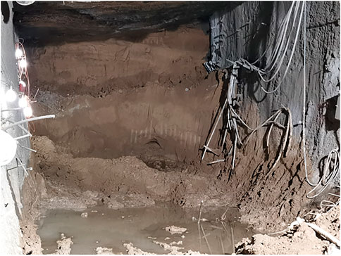
FIGURE 1. Groundwater level line.
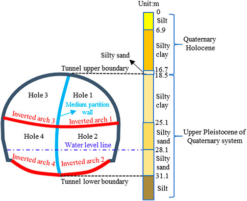
FIGURE 2. Location of the tunnel in relation to the strata.
CRD is an excavating method that divides a section up and down and left and right, with the next door and elevated arch.
Based on the existing large-span tunnel construction status and construction experience, the main construction methods are as follows: center diaphragm, CRD, double-side heading, full-section excavation, and bench methods.
To monitor the surface deformation information in real time, 11 surface subsidence observation points were set up in the DK33+201 mileage section. The location of the monitoring points above the tunnel is depicted in Figure 3.
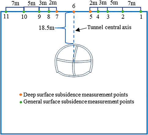
FIGURE 3. Monitoring point layout diagram.
Monitoring points 1, 2, 10, and 11 are far away from the tunnel median, and the amount of surface settlement is relatively small. Therefore, the surface deep settlement monitoring point 6 at the tunnel median/surface junction, as well as the remaining two deep settlement monitoring points 5 and 7, and four general settlement monitoring points 3, 4, 8, and 9 near the deep settlement monitoring points, were chosen. Figure 4 depicts the monitored surface settlement data from the beginning of construction to the current progress at the seven monitoring sites.
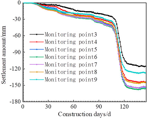
FIGURE 4. DK+201 surface measurement point subsidence temporal curve.
As shown in Figure 4, the time of the steep increase in the settlement at surface monitoring points 3–9 of the DK33+201 section is consistent with the time of tunnel boring 1–4 to this section, and the settlement increases approximately linearly with the time when the four excavated parts are dug to this section, respectively. The excavation of Hole 1 has the greatest impact on surface settlement, and its contribution to surface settlement can reach 41.67%, followed by the excavation of Hole 3, with its contribution to surface settlement reaching 27.48%; whereas the excavation of holes 2 and 4 contributes 18.23% and 12.62% to surface settlement, respectively. After tunnel boring, each measurement point reflects that the surface settlement gradually stabilizes, with the curves cut between the excavation of Hole 1 and Hole 4 excavation to calculate the relative deviations of the slope of the seven curves and the slope of the cut line at the measurement point 6.
The average increment in surface settlement is illustrated in Table 1. Table 1 shows that the closer the ground surface is to the tunnel’s centerline, the greater the average settlement is during tunnel excavation. The corresponding average increase in surface settlement within the area, where only the tunnel cross-section is located, has a minor difference. The greater the distance from the tunnel’s centerline, the less the excavation affects ground settlement and the smaller the average surface increment.
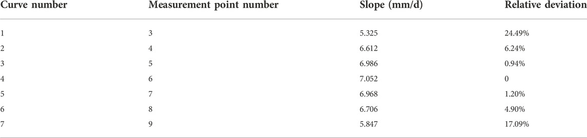
TABLE 1. Average increment of surface subsidence.
The influence range of a circular tunnel on the stress redistribution in the surrounding rock is approximately one time the diameter of the tunnel (Xiao et al., 1987), and the entire span of the tunnel is 14 m, the height is 12.6 m, and the vault is buried 18.5 m from the surface, so the stratigraphic model is constructed by extending the stratigraphic model from the outer contour of the tunnel twice the length of the tunnel span to the left, right, and lower sides, respectively. The numerical simulation calculation model is depicted in Figure 5. The PLANE42 element in ANSYS software is used as the model soil element and the BEAM3 element as the supporting one, with the displacement on both the left and right sides of the model fixed to the x-direction and that on its lower side fixed to the y-direction as the boundary conditions.
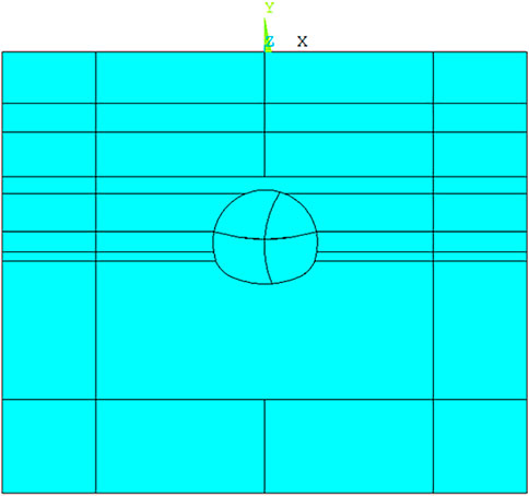
FIGURE 5. Calculation model diagram.
According to the geological survey report, the calculated parameters of each stratum are listed in Table 2, and the intensity of the stratum below the water table line is discounted to 70% of the original parameters (Zhang et al., 2003).
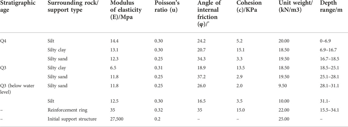
TABLE 2. Numerical simulation parameter values table.
The simulated excavation process is divided into four steps, with a numbering sequence of holes 1–4, all of which use full-section excavation and apply initial support after excavation, which is consistent with the excavation sequence and process on site. The evolution of settlement deformation during the simulated tunnel excavation process is illustrated in Figure 6.
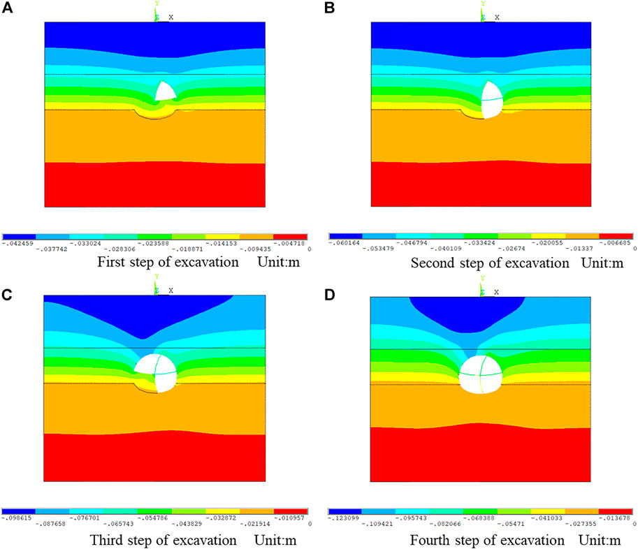
FIGURE 6. Y-direction displacement cloud. (A) First step of excavation, unit: m. (B) Second step of excavation, unit: m. (C) Third step of excavation, unit: m. (D) Fourth step of excavation, unit: m.
The amount of surface settlement increases with increasing tunnel excavation. After the termination of tunnel excavation, the main influence area of surface settlement gradually shrinks, forming a radial area with the centerline of the tunnel as the reference line toward the surface (the area represented by dark blue in Figure 6D), which has the same distribution trend as the field-monitoring point response. The numerical simulation results of the surface settlement and field-monitoring data were compared and analyzed, and the results of the comparative analysis are shown in Figure 7. The relative errors of the final settlement of field monitoring and those of the numerical simulation are shown in Table 3.
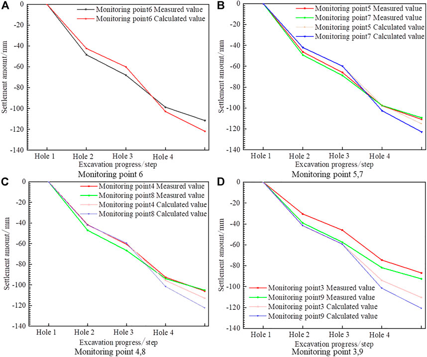
FIGURE 7. Comparison of measured and calculated values of surface settlement at different measurement points. (A) Monitoring point 6. (B) Monitoring points 5 and 7. (C) Monitoring points 4 and 8. (D) Monitoring points 3 and 9.
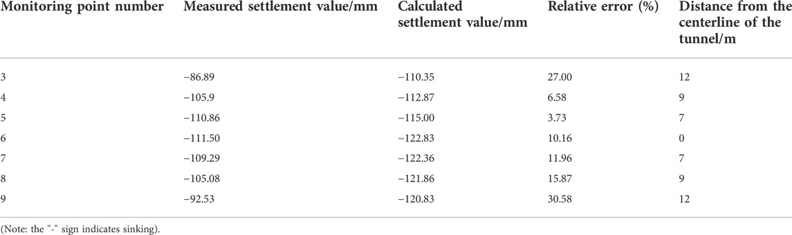
TABLE 3. Relative error between measured and calculated values of final ground settlement.
The proportion of the excavation of Hole 1 accounts for 35.71% of the total surface settlement, followed by the excavation of Hole 3, which accounts for 33.15%, and holes 2 and 4 accounting for 16.16% and 14.98%, respectively. Comparing the numerical simulation results with the measured value, the proportion of Hole 1 decreases by 5.96%, that of Hole 3 increases by 5.67%, and those of holes 2 and 4 do not change significantly: the proportion of Hole 2 decreases by 2.07% and that of Hole 4 decreases by 2.36%. The measured value of the surface settlement is maintained at the same level within 9 m from the tunnel’s centerline, with an average value of 108.5 mm, and there is a significant decreasing trend in the surface settlement caused by the tunnel excavation above 9 m from the tunnel’s centerline. The relative error between the results of the numerical simulation within 9 m from the tunnel’s centerline and the measured value is not greater than 15.97%, and the relative error between the results of the surface settlement simulation more than 9 m from the tunnel’s centerline and the measured value is approximately 30%. The aforementioned data show that the numerical simulation of the surface of a certain range can reflect real surface settlement changes, the range of which is 0.64–0.86 times the tunnel’s centerline. The differences between numerical simulation and field monitoring may be because of the complex stratigraphic distribution of the site, the fact that the stratigraphic model used in the simulation is determined by the part excavated and explored with the DK+201 section distribution, or that the distribution of a layer is assumed uniform in depth in the numerical simulation; the assumed position of the water table line in the numerical simulation is the highest water table line; for the physical and mechanical parameters of the strata below the water table line, only gravity reduction and strength discounting are considered.
To further control surface settlement, full-section overburden grouting is proposed in the subsequent excavation to pre-reinforce the strata; the excavation method of reserving the core soil is adopted for holes 1 and 3, and the step method is adopted for holes 2 and 4 to reduce the critical surface of one excavation. The auxiliary construction collaborative excavation process is depicted in Figure 8.
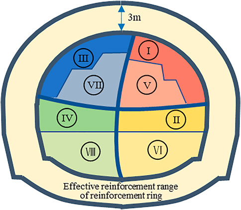
FIGURE 8. Schematic diagram of the new excavation process.
Figure 9 shows the calculated model with the displacement cloud in the y-direction after excavation. Figures 6D, 9B show that after grouting and using the pre-core soil with the step method excavation process, the displacement around the shallow-buried tunnel is well controlled, the favorable effect of reinforcement radiates to the surface, and the maximum settlement of the surface is 103.94 mm.
FIGURE 9. Calculation model and calculation results. (A) Computational model. (B) Y-direction displacement cloud, unit: m.
Table 4 compares the calculated values of surface settlement for the new and old excavation methods. Comparing the surface settlement displacements at monitoring point 6, the results show that the surface settlement caused by the new method in the corresponding excavation stage is generally reduced by approximately 15% compared with that caused by the original method. The new process plays a certain role in controlling surface settlement. On this basis, the surface settlement rate can be controlled by increasing the strength of the initial support and the strength of the second lining support so that the accumulated settlement of important buildings on the surface is within the control value.
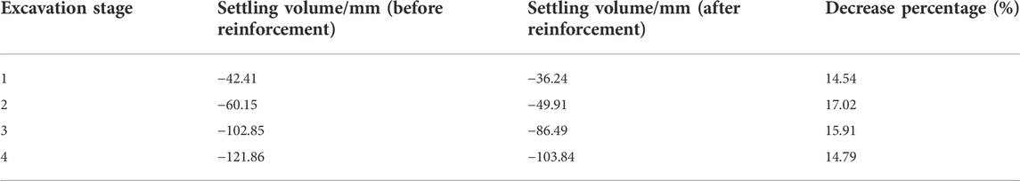
TABLE 4. Comparison of the calculated values of surface settlement between the new method and the old method.
The material point method combines the advantages of the Lagrangian and Eulerian methods and has advantages in modeling significant deformation (Dong et al., 2021). By studying the transient impact process of a submarine landslide on pipelines and the effect on the parameters with regard to the landslide quality, Fan et al. (2022) elucidated the formation mechanism of the transient impact force based on the characteristic analysis of flow velocity and acceleration fields around the pipeline during the slide–pipeline interaction. Wang et al. (2021) proposed a general framework for analyzing the spatial and temporal evolution of multistage riparian landslides that applied a three-dimensional geological model to integrate a large amount of data from surface surveys, subsurface exploration, in situ monitoring, and geological mapping and to predict landslide triggers based on these data.
The top of a shallow-buried tunnel is typically buried within 20 m of the surface. Because of the tunnel’s shallow depth, excavation construction will disturb the ground surface and upper buildings, which may lead to the collapse of the ground surface and the tunnel without notice, causing unnecessary safety accidents. The common full-section excavation method should not be used in tunneling shallow-buried tunnels because it can cause uncontrolled displacement and even lead to tunnel collapse resulting from excessive one-time excavation and excessive soil deformation. In this study, the CRD method was adopted for the initial excavation to ensure that the construction proceeded as scheduled without operational accidents, and the field-monitoring data were combined with numerical simulation tools to investigate the effect of the CRD method on surface deformation characteristics in shallow-buried tunnels. Overall, the findings show that after applying the CRD method, the surface settlement caused by the upper cavern excavation (holes 1 and 3) accounts for the majority of the total surface settlement, approximately 70%, with the excavation sequence and the spatial relative position of the caves being presumed as the main influencing factors. Hole 1 was excavated first, which is equivalent to directly removing a part of the originally complete plane, and the stress change caused by it can be transferred to the ground surface through the surrounding rocks in the upper part of the hole, so the surface settlement caused by it is the largest among the four steps. After that, Hole 2 is excavated, whose spatial location is directly below Hole 1. Because the body of Hole 1 has been excavated, there is no medium to transmit the change in stress distribution caused by the excavation of the body of Hole 2; thus, the stress change caused therein is transmitted from the surrounding rock bodies on the left and right sides of the Hole 2 body to the surroundings and then to the surface, so the amount of surface settlement caused by the excavation of Hole 2 is smaller than that of Hole 1, i.e., only approximately 15–18%. The surface settlement caused by the excavation of Hole 3 is the second largest, only 2.5% smaller than that of Hole 1, based on the calculated average of each measurement point. Because the distance from these two holes to the surface is the same, the transfer processes of stress changes caused therein to the surface are similar. The surface settlement caused by the excavation of Hole 4 accounts for 12–15%, with its effect consistent with that of Hole 2.
With the CRD method, outstanding tunnels will not be excavated unless and until their surrounding rocks are reinforced by applying the full-section overburden grouting method to further control the surface settlement, after which the mechanical strength (including cohesion, internal friction angle, and elastic modulus) of the surrounding rocks will increase, and the displacement of these rocks caused by the stress during tunneling is smaller than that of the unreinforced rocks, which in turn causes less surface settlement. On this basis, the core soil is reserved during excavation as soil strength support. Reserving the core soil while applying the bench tunneling method is to reduce soil deformation by further reducing the earthwork volume of one excavation and the area of the free face. The adoption of the new method can further reduce the amount of surface settlement. In areas with complex ground strata, the deformation characteristics and deformation rates of tunnels can be found in time by monitoring using this method, and the excavation method, supporting method, and soil strength can be dynamically adjusted to protect important buildings on the ground.
In this study, data were analyzed by monitoring on-site surface settlement in a section of an under-construction railroad tunnel beneath a highway. Finite element software was used to analyze the surface settlement pattern caused by the concealed excavation under weak surrounding rocks using the shallow-buried tunnel CRD method, and the research results were compared with the actual settlement on site, and suggestions for adjusting subsequent excavation plans were made as follows:
(1) For the construction of a shallow-buried tunnel using the CRD method, the amount of surface settlement caused by the excavation of Hole 1 can account for 40% of the total amount, followed by the excavation of Hole 3, accounting for 30% of the total amount of surface settlement, and the difference between the amount of surface settlement caused by the excavation of holes 2 and 4 is insignificant. In the subsequent excavation process, the excavation plans of holes 1 and 3 should mainly be adjusted.
(2) The distance from the centerline of the tunnel to 0.64–0.86 times the diameter of the tunnel has the greatest influence on surface settlement in shallow-buried tunnels using the CRD method. The farther the distance from the tunnel’s centerline, the less the ground settlement is affected. The finite element numerical simulation prediction for surface settlement within the main influence range is credible.
(3) The calculated value of surface settlement is slightly larger than the measured value of the surface settlement, and its relative error is in the range of 3.73–30.58%; the distance of the monitoring point from the center of the tunnel decreases, and its error exhibits a decreasing trend.
(4) In the CRD excavation method, the auxiliary construction can effectively reduce the amount of surface settlement by approximately 15%. On this basis, the strength of the subsequent support can be enhanced, and the excavation process can be flexibly adjusted to control the amount of surface settlement.
The original contributions presented in the study are included in the article/Supplementary Material; further inquiries can be directed to the corresponding authors.
LZ, KC, and YP were responsible for writing. GZ, PC, GZ, PC, and YG provided engineering data and performed geophysical analysis. FX, YZ, and GN were responsible for numerical simulation analysis. HX, TW, and PZ were responsible for the ancillary construction synergy analysis. YP was responsible for review and proofreading. FL was responsible for producing pictures.
This research was supported by the On-campus Talent Introduction Project at Xihua University (No. Z201125) and the Natural Science Foundation of Sichuan (2022NSFSC1025).
The authors LZ, PeC, GZ, PaC, FX, YZ, GN, HX, TW and PZ were employed by The 5th Engineering Co., Ltd. of China Railway Construction Bridge Engineering Bureau Group. The author YP was employed by Sichuan Huadi Construction Engineering Co., Ltd. The authors KC and GZ were employed by Sichuan Communication Surveying and Design Institute Co., Ltd.
The remaining authors declare that the research was conducted in the absence of any commercial or financial relationships that could be construed as a potential conflict of interest.
All claims expressed in this article are solely those of the authors and do not necessarily represent those of their affiliated organizations, or those of the publisher, the editors, and the reviewers. Any product that may be evaluated in this article, or claim that may be made by its manufacturer, is not guaranteed or endorsed by the publisher.
Al–Damluji, O. F. S., Fattah, M. Y., and Al-Adthami, R. A. J. (2011). Analysis of soil media containing cavities or tunnels by the boundary element method. J. Alhosn Univ. J. Eng. Appl. Sci. 3 (2), 27–49.
Dong, Y. K., Cui, L., and Zhang, X. (2022). Multiple-GPU parallelization of three-dimensional material point method based on single-root complex. Int. J. Numer. Methods Eng. 123 (2), 1481–1504. doi:10.1002/nme.6906
Duan, J., Huang, C. R., Cui, X. Y., Li, K., and Guo, H. Y. (2019). Evaluation of a tunnel in Yunnan using CRD construction method. E3S Web Conf. 136 (3), 04020. doi:10.1051/e3sconf/201913604020
Ebrahim, F. S., Majidreza, N., and Anna, G. (2017). A numerical investigation of sinkhole subsidence development over shallow excavations in tectonised weak rocks: The dolaei tunnel’s excavation case. Geotech. Geol. Eng. (Dordr). 35 (4), 1685–1716. doi:10.1007/s10706-017-0202-3
Fan, N., Jiang, J. X., Dong, Y. K., Guo, L., and Song, L. F. (2022). Approach for evaluating instantaneous impact forces during submarine slide-pipeline interaction considering the inertial action. Ocean. Eng. 245 (6), 110466. doi:10.1016/j.oceaneng.2021.110466
Fattah, M. Y., Hamood, M. J., and Dawood, S. H. (2015). Dynamic response of a lined tunnel with transmitting boundaries. Earthquakes Struct. 8 (1), 275–304. doi:10.12989/EAS.2015.8.1.275
Fattah, M. Y., Shlash, K. T., and al-Soud, M. S. (2012). Boundary element analysis of a lined tunnel problem. ije. 25 (2), 89–97. doi:10.5829/idosi.ije.2012.25.02b.02
Fattah, M. Y., Shlash, K. T., and Salim, N. M. (2011a). Effect of reduced zone on time-dependent analysis of tunnels. Adv. Civ. Eng. 12 (4), 1. doi:10.1155/2011/963502
Fattah, M. Y., Shlash, K. T., and Salim, N. M. (2013). Prediction of settlement trough induced by tunneling in cohesive ground. Acta Geotech. 8, 167–179. doi:10.1007/s11440-012-0169-4
Fattah, M. Y., Shlash, K. T., and Salim, N. M. (2011b). Settlement trough due to tunneling in cohesive ground. J. Indian Geotechnical J. 41 (2), 64–75.
Gang, W., Hui, J. Q., and Xin, J. W. (2012). Analysis of settlement reasons and mechanism in immersed tunnel. J. Appl. Mech. Mater. 238, 803–807. doi:10.4028/www.scientific.net/amm.238.803
Javad, S., and Hadi, H. S. (2015). Tehran subway tunnel settlement analysis by using analytical, experimental and numerical methods (case study: Station of Imam Ali university). J. Int. J. Sci. Eng. Technol. 4 (5), 325–328. doi:10.17950/ijset/v4s5/513
Jin, D. L., Yuan, D. J., Li, X. G., and Zheng, H. T. (2018). Analysis of the settlement of an existing tunnel induced by shield tunneling underneath. Tunn. Undergr. Space Technol. 81, 209–220. doi:10.1016/j.tust.2018.06.035
Lai, H. P., Zheng, H. W., Chen, R., Kang, Z., and Liu, Y. (2020). Settlement behaviors of existing tunnel caused by obliquely under-crossing shield tunneling in close proximity with small intersection angle. Tunn. Undergr. Space Technol. 97, 103258. doi:10.1016/j.tust.2019.103258
Li, F. K., Gong, H. L., Chen, B. B., Gao, M. L., and Zhou, C. F. (2020). Subsidence monitoring with TerraSAR-X data in beijing central business district and subway tunnelings, China. Proc. IAHS. 382, 125–130. doi:10.5194/piahs-382-125-2020
Li, J., Wang, Z. L., and Zhong, J. F. (2014). Force state of country rock and supporting structure in multi-arch tunnel under central hole + CRD method. J. Appl. Mech. Mater. 580-583, 1192–1196. doi:10.4028/www.scientific.net/amm.580-583.1192net/AMM.580-583.1192
Li, W. (2008). ANSYS example analysis of tunnel and underground engineering. Yichang, China; Water&Power Press.
Liu, Z. Y., Xue, J. F., Ye, J. Z., and Qian, J. G. (2021). A simplified two-stage method to estimate the settlement and bending moment of upper tunnel considering the interaction of undercrossing twin tunnels. Transp. Geotech. 29 (9), 100558. doi:10.1016/j.trgeo.2021.100558
Qi, Y. J., Wei, G., Xie, Y., and Wang, Q. (2021). Effect of grouting reinforcement on settlement of existing tunnels: Case study of a new crossing underpass. Symmetry (Basel). 13 (3), 482. doi:10.3390/sym13030482
Shang, H., Zhan, H. Z., Ni, W. K., Liu, Y., Gan, Z. H., and Liu, S. H. (2022). Surface environmental evolution monitoring in coal mining subsidence area based on multi-source Remote sensing data. Front. Earth Sci. (Lausanne). 10. doi:10.3389/feart.2022.790737
Tang, P., Chen, G. Q., Huang, R. Q., and Wang, D. (2021). Effect of the number of coplanar rock bridges on the shear strength and stability of slopes with the same discontinuity persistence. Bull. Eng. Geol. Environ. 80 (5), 3675–3691. doi:10.1007/s10064-021-02180-y
Tang, P., Chen, G. Q., Huang, R. Q., and Zhu, J. (2020). Brittle failure of rockslides linked to the rock bridge length effect. Landslides 17 (4), 793–803. doi:10.1007/s10346-019-01323-3
Wang, J., Schweizer, D., Liu, Q., Su, A., Hu, X., and Blum, P. (2021). Three-dimensional landslide evolution model at the Yangtze River. Eng. Geol. 292 (1), 106275. doi:10.1016/j.enggeo.2021.106275
Wang, K. (2012). Theoretical calculation and parametric analysis of tunnel settlements due to neighboring over-length pile groups. J. Appl. Mech. Mater. 238, 769–772. doi:10.4028/www.scientific.net/amm.238.769net/AMM.238.769
Wang, P., Xu, S. Y., Shao, S. J., Wang, H. J., Li, X. D., and Qian, Z. L. (2022). Mesoscopic characteristics and performance evaluation of loess treated by different anti-seismic subsidence technologies. Front. Earth Sci. (Lausanne). 9. doi:10.3389/feart.2021.762508
Wang, Z. W., Yang, R. H., Guo, H. Y., and Li, K. (2020). Study on key construction procedures of CRD method for Re shuitang No.3 tunnel. IOP Conf. Ser. Mat. Sci. Eng. 711 (1), 012074. doi:10.1088/1757-899X/711/1/012074
Wu, H. N., Shen, S. L., and Yang, J. (2017). Identification of tunnel settlement caused by land subsidence in soft deposit of shanghai. J. Perform. Constr. Facil. 31 (6). doi:10.1061/(ASCE)CF.1943-5509.0001082
Xiao, S. F., and Yang, S. B. (1987). Rock Mechanics. M. Geological Publishing House Co., Ltd., Beijing, China, 211.
Yan, N., Jing, D. S., Sang, S. K., Bai, X. Y., Liu, X. Y., et al. (2022). An investigation on longitudinal surface subsidence deformation of large-span undercut metro tunnel. Front. Earth Sci. (Lausanne). 10, 839242. doi:10.3389/feart.2022.839242
Zhang, F. Z., Chen, X. P., and WuHuang, H. F. G. Y. (2003). The characteristic of residual strength of soft clayey rocks of the east river-shenzhen water supply project. J. J. Eng. Geol. 11 (01), 54–57.
Zhang, N., Zhang, G. W., Liu, R. H., Gao, H. J., and Gong, H. X. (2019). Optimization analysis of step length in tunnel construction by bench method. J. Highw. 64 (10), 299–303.
Keywords: shallow-buried tunnel, ground surface settlement, CRD, on-site supervision, over-grouting
Citation: Zhang L, Pan Y, Chen K, Zheng G, Gao Y, Chen P, Zhong G, Chen P, Xu F, Zhang Y, Nan G, Xue H, Wang T, Zhao P and Lu F (2023) The effect of CRD method and auxiliary construction on surface settlement in shallow-buried tunnels. Front. Earth Sci. 10:998717. doi: 10.3389/feart.2022.998717
Received: 20 July 2022; Accepted: 26 September 2022;
Published: 10 January 2023.
Edited by:
Yunhui Zhang, Southwest Jiaotong University, ChinaReviewed by:
Mohammed Y Fattah, University of Technology, IraqCopyright © 2023 Zhang, Pan, Chen, Zheng, Gao, Chen, Zhong, Chen, Xu, Zhang, Nan, Xue, Wang, Zhao and Lu. This is an open-access article distributed under the terms of the Creative Commons Attribution License (CC BY). The use, distribution or reproduction in other forums is permitted, provided the original author(s) and the copyright owner(s) are credited and that the original publication in this journal is cited, in accordance with accepted academic practice. No use, distribution or reproduction is permitted which does not comply with these terms.
*Correspondence: Yuangui Pan, cGFueXVhbmd1aUAxMjYuY29t; Kezhu Chen, a2VwbGVyY2hlbjE1NjdAMTI2LmNvbQ==
Disclaimer: All claims expressed in this article are solely those of the authors and do not necessarily represent those of their affiliated organizations, or those of the publisher, the editors and the reviewers. Any product that may be evaluated in this article or claim that may be made by its manufacturer is not guaranteed or endorsed by the publisher.
Research integrity at Frontiers
Learn more about the work of our research integrity team to safeguard the quality of each article we publish.