 Jun Pei1,2*
 Na Wei1,2*
 Boning Zhang3Jinzhou Zhao1,2Bjørn Kvamme1
 Richard B. Coffin1Haitao Li1,2,4Ruiling Bai1,2
- 1State Key Laboratory of Oil and Gas Reservoir Geology and Exploitation, Southwest Petroleum University, Chengdu, China
- 2State Key Laboratory of Natural Gas Hydrate, Beijing, China
- 3Chengdu North Petroleum Exploration and Development Technology Co., Ltd., Chengdu, China
- 4State Key Laboratory of Coal Mine Disaster Dynamics and Control, Chongqing University, Chongqing, China
The drilling fluid invasion into hydrate-bearing sediments will change the geomechanical properties of the reservoir and may lead to uncontrolled geological disasters in the worst case. Native sediments are replaced with artificial samples in this study to investigate the effect of drilling fluid invasion on the strength behaviors of hydrate-bearing sediments. The triaxial test is used primarily to assess the strength behaviors of hydrate-bearing sediments at varying temperatures, pressures, and hydrate saturation levels. The process of water-based drilling fluid penetrating into hydrate-bearing sediments is then experimentally imitated under various experimental conditions, with reservoir temperature of 4°C and pore pressure of 10 MPa. The possible repercussions of drilling fluid invasion and hydrate phase transition are identified by testing the mechanical properties of sediments under various invasion times and temperatures. The findings reveal that when hydrate saturation rises from 5% to 35%, the gas hydrate sediments shift from strain hardening to strain softening, with the critical hydrate saturation value of transition is between 15% and 25%. Peak strength increases with increasing hydrate saturation and pressure, and decreases with increasing temperature, whether drilling fluid invasion is present or not. The peak strength, Young’s modulus, shear modulus, and secant modulus of hydrate sediments all decreased significantly after drilling fluid invasion, although the Poisson’s ratio rose. These mechanical parameters are related to temperature and pressure under the action of drilling fluid. Finally, engineering and research recommendations for reducing the risk of drilling fluid invasion and hydrate dissociation are made based on experimental findings and theoretical analysis. This study innovatively examine the geomechanical mechanical properties of drilling fluid invading hydrate reservoir, which is critical for avoiding production concerns.
1 Introduction
Natural gas hydrate is a caged crystalline compound, commonly known as combustible ice (Sloan and Koh., 2007; Sun et al., 2021). It is known for its abundant energy reserves, wide distribution, high calorific value and high-energy density, which makes it an ideal low-carbon fuel. The special environment of deep-water seafloor can provide suitable temperature and pressure conditions for the generation of natural gas hydrate. The continental shelf, mid-ocean ridge and trench are ideal areas for gas hydrate generation. It is estimated that 20.7% of the global land and 90% of the deep-water seafloor have conditions conducive to the generation of gas hydrate, of which about 95% of the gas hydrate is stored in the deep-sea area (Ye and Liu., 2013; Sun et al., 2021). Currently the reserves of natural gas hydrate in the world has so far proved inconclusive. According to USGS data from the year 2000, the quantity of energy trapped in hydrate is likely more than twice that of all energy in known fossil fuels (coal, oil, and gas) (Kvamme, 2020). The widely quoted view article that could be used to estimate the reserves, provided by Boswell and Collett, yielded a global gas hydrate gas-in-place resources of 3 × 10¹⁵ m3 (Boswell and Collett, 2011; Wang and Wang, 2020). Various signs show that natural gas hydrate may become an alternative energy after shale gas and coalbed methane. Marine gas hydrate with huge reserves will become the main area of exploration and development in the future.
Methane and/or other small non-polar, or slightly polar hydrocarbons can form hydrate with water (or ice) under high pressure and low temperature. Some inorganic pollutants in natural gas, like for instance CO2 and H2S, are also very efficient hydrate formers (Chibura et al., 2022). Sources of gas to natural gas hydrate are either from thermogenic degradation of organic material deep down in sediments, or from biogenic degradation of organic material in the upper crust (Stolper et al., 2014; Dai et al., 2017; Liang et al., 2022). The majority of global resources reside in marine sediments beneath the seafloor, at temperatures and pressures within the hydrate stability region (Jang et al., 2019; Cui et al., 2021; Wei et al., 2022). If the seafloor conditions are outside the hydrate forming conditions, this will result in direct fluxes of natural gas to the ocean, and in some cases bubbling of gas all the way to the air (Kvamme and Saeidi, 2021). If the seafloor openings of the fractures are at hydrate forming depths, and temperatures are inside hydrate generation, then an unstable situation will establish. This type of hydrate mounds on the seafloor can be found numerous places round the world and give rise to bio geo ecosystems. In nature, environments such as the permafrost, the submarine sediments on the active and passive continental margins are suitable for hydrate occurrence. It is found that the main occurrence areas of gas hydrate are the accretionary wedges on the active continental margins and geological structures such as cold spring vents, mounds, faults, mud volcanoes and diapirs on the passive continental margins. At present, hydrate reservoirs found in marine environment are mainly distributed along the coast of India, the Sea of Japan, the Nankai Trough, the Gulf of Mexico, the Atlantic coast of the USA, the margin of the Arctic Ocean, the Cascadia margin, the Bering Strait, the South China Sea, the Ulleung Basin, the Niger Delta Basin, the coastal Trinidad and Tobago (Sun et al., 2011; Chong et al., 2016; Hu et al., 2021).
Historically, the interest in offshore natural gas hydrate as an energy source has risen considerably during the latest four decades. The distribution, occurrence, properties, exploration and development methods of gas hydrate have always been the focus of research. Countries that are very interested in gas hydrate include developed countries such as the United States, Canada, Norway, Japan, South Korea and Germany, as well as emerging economies such as China, India and Russia. Significant progress have been made in our understanding of the properties of hydrate reservoir and its exploration and development methods. It is realized that the development of natural gas hydrate, an unconventional energy with great potential, can not only meet the growing energy demand, but also help to reduce carbon dioxide emissions (Lee et al., 2003; Yin and Linga, 2019). However, the traditional oil and gas development technology is not completely applicable to the development of natural gas hydrate. At present, the production methods of natural gas hydrate are mainly depressurization, thermal stimulation, CO2-CH4 replacement, chemical inhibitor injection, etc. (Lee et al., 2003; Chong et al., 2016; Li et al., 2016; Yin and Linga, 2019). These methods are faced with problems such as formation instability, sand control and prevention. In recent years, the solid fluidization method proposed by our team has also been widely reported (Zhou et al., 2018a; Wei N. et al., 2019; Zhou et al., 2020). After 2000, these methods have been verified by short-term trial production in the field. In 2002, although the production efficiency was not satisfactory, the trial production experiment conducted in permafrost Mallik for about 5 days verified the effectiveness of the thermal stimulation method for the first time (Yin and Linga, 2019). Then in 2007 and 2008, the depressurization method was used to conduct two trial production in this region, producing 830 and 13,200 m3 of natural gas respectively (Huang et al., 2009; Yin and Linga, 2019). In 2012, the CO2-CH4 replacement method was combined with the depressurization, producing a total of 24,000 m3 of natural gas on the North Slope of Alaska in 30 days (Wang and Lau, 2020). The trial production of gas hydrate in permafrost areas also includes scientific research in Qilian Mountain, Tibet, China in 2011 and 2016 (Li et al., 2018; Liang et al., 2020). It was not until 2013 that the first trial production project of marine gas hydrate in the world was successfully implemented. The first attempt in the Daini–Atsumi Knoll off Honshu Island produced 119,000 m3 of methane applying the depressurization method. Four years later, Japan conducted the second production of methane hydrate using two producer wells sequentially in the Nankai Trough (Yamamoto et al., 2019). A key problem in production technology is the limited understanding of the geomechanics of gas hydrate sediments. This problem became very obvious even in the field experiments in Alaska and Nankai Trough. Sediment movement and uncontrolled sand production occurred in both places. Although the initial goals have not been fully achieved, unprecedented achievements have been made and all countries concerned should learn from Japan. After that, China conducted two depressurization production in the South China Sea in 2017 and 2020, producing 309000 and 861,400 m3 of natural gas respectively (Ye et al., 2020; Zhang et al., 2022). The world’s first solid-state fluidization trial production was almost carried out at the same time as China’s first depressurization trial production. This new technique for non-diagenetic hydrate has achieved a recovery of up to 80.1% in the first attempt (Zhou et al., 2018b; Zhou et al., 2020). Nevertheless, some technical problems such as sand production, water production, wellbore stability, methane leakage and so on, have not been well solved in the past, which have seriously affected the commercialization of gas hydrate. At present, the study of geomechanical properties and other physical properties of natural gas hydrate reservoir is of great significance for logging evaluation and reservoir stability evaluation of natural gas hydrate reservoir. Considering the possible energy crisis in the future and the great potential of gas hydrate, it is necessary to conduct an in-depth study of these unsolved problems.
The invasion of drilling fluid into hydrate reservoir is an important and unsolved problem. In the drilling process of marine hydrate reservoir, the drilling fluid will penetrate into the hydrate-bearing sediment and displace the original water and gas in the formation due to the pressure difference. As a result, the initial temperature, pressure and salinity conditions of hydrate reservoir will change. Natural gas hydrate are not thermodynamically stable and the existence of commercial concentrations of hydrate is only possible when the hydrate deposits are sealed by clay, shale and other sediments of very low permeability (Cui et al., 2021; Sun et al., 2022). Drilling through hydrate filled sediments will increase the temperature in the regions surrounding the borehole, which is mainly due to the high temperature of the drilling fluid itself and the heat generated by the friction of drilling tools. And the drilling fluid by itself contains ions as well as polar fluids that significantly affect the activity of the water. Both effects will lead to local dissociation of hydrate. The water and gas produced by hydrate dissociation, together with the initially invaded drilling fluid, are driven further away from the bottom of the wellbore by the newly entered drilling fluid. As such the invasion of drilling fluid in hydrate reservoir is accompanied by hydrate dissociation and heat transfer. One concern is that released gas can leak through annulus along with the returning drilling mud. Other possible leakage pathways include passages between the outside of the pipeline and the sediments. The impact of the temperature increase is unique for every specific hydrate reservoir and depends on the super saturation, i.e., free energy of the hydrate at actual pressure and temperature relative to free energy of the hydrate at pressure temperature stability conditions. For illustration, we plot stability limits of hydrate in temperature pressure projection and in projection of CH4 concentration in surrounding water in Figure 1. Increased temperature, reduced pressure or inhibitors that bring the system outside hydrate stability, and keep this condition outside stability, will lead to hydrate dissociation. Like, for instance, the invasion of drilling fluid into hydrate reservoir. In short, these effects cause changes in mechanical, electrical, thermodynamic properties and permeability of the reservoir, affecting the stability of formation and the reliability of logging during drilling. It may lead to poor rheology of drilling fluid and wellbore instability. This complex process will be described and analyzed in detail in the next section.
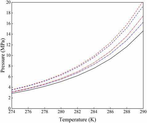
FIGURE 1. The solid curve is hydrate stability limit for hydrate formed from pure water and CH4, red dash-dot is for hydrate formed from a 2 wt% methanol in water solution and CH4, blue dash-dot is for hydrate formed from a 2 wt% NaCl in water solution and CH4, red dashed is for hydrate formed from water in a 5 wt% methanol in water solution and CH4, and blue dashed is for hydrate formed from water in a 5 wt% NaCl in water solution and CH4.
Evaluating the strength behaviors of hydrate reservoirs and studying the response process of drilling fluid invading the formation near the wellbore in drilling is of great significance to logging evaluation, safe drilling, reservoir protection, and gas production. In recent years, researchers from many countries and regions have studied the geomechanical properties of hydrate-bearing sediment during dissociation. Great progress has been made in sample preparation, parameter testing, temperature and pressure control, model verification and so on. So far, a laboratory-field and macro-micro experimental system of hydrate-bearing sediment mechanics have been preliminarily formed. The macroscopic mechanical properties of hydrate deposits are revealed by triaxial experiments based on classical soil mechanics, and the microscopic experiments based on CT, nuclear magnetic resonance (NMR), and scanning electron microscopy (SEM) are helpful to clarify their geomechanical mechanism (Park et al., 2018; Wu et al., 2018; Liu et al., 2019; Tian et al., 2019). In previous studies, the research of drilling fluid invading hydrate reservoir focused on the impact of drilling activities on hydrate reservoirs. The influence of drilling fluid invasion is usually ignored in the design of drilling fluid. To our knowledge, there are many numerical simulation studies on the changes of physical parameters of hydrate-bearing sediments in the process of invasion, but few related experimental studies, especially the impact of drilling fluid invasion on reservoir geomechanical properties. At present, most of the studies on the geomechanical properties of hydrate-bearing sediments are carried out without drilling fluid, and there is a lack of experimental study on the change of reservoir properties after drilling fluid invasion. See Table 1 for some studies on the physical parameters of hydrate-bearing sediments during the invasion process of drilling fluid in recent years.
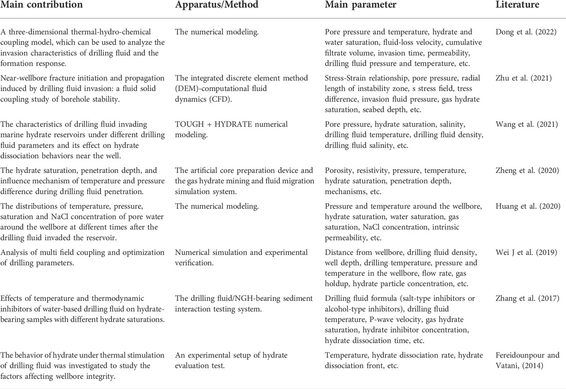
TABLE 1. Some theoretical research and experimental studies on the physical parameters of drilling fluid invasion into gas hydrate sediments in recent years.
The commercial application needs further investigations on the geotechnical and mechanical characteristics of hydrate-bearing sediments after drilling fluid intrudes into hydrate reservoirs. For these purposes, laboratory studies is more time-saving and labor-saving than field tests. Using artificial cores as the experimental sample, we will investigate the effects of drilling fluid invasion at various temperatures and invasion times on the geomechanical properties of gas hydrate deposits in this work. The stress-strain and other geomechanical properties of 16 groups of hydrate-bearing sediments under different temperature, pressure and saturation were measured. Then, the invasion temperature and time of drilling fluid was changed under different saturation conditions, and the changes of geomechanical properties after hydrate dissociation were measured experimentally. The hydrate saturation range of the experiment is roughly controlled at 5%–35%. There are two choices of drilling fluid temperature, and there are three levels of invasion time, with a total of 24 groups of drilling fluid invasion experiments. Additionally, the effects and risks caused by hydrate dissociation after drilling fluid invasion during drilling are analyzed and evaluated. Engineering suggestions are put forward to ensure that industrial personnel can perform their work safely and efficiently.
2 Possible effects of hydrate dissociation and reservoir properties due to drilling fluid invasion
Drilling gas hydrate reservoirs is often thought to be dangerous. Common concerns include well plugging, blowout, wellbore stability, formation collapse, and landslides (Merey, 2016). In our previous work, we paid more attention to the engineering parameters, consequences and risks of wellbore multiphase flow in the process of marine gas hydrate drilling (Wei et al., 2018; Wei N. et al., 2019; Sun et al., 2021; Sun et al., 2022). Here we focus on the effects of drilling fluid invasion on the hydrate generation and dissociation. The drilling fluid in the wellbore will exchange material and energy with seawater and the formation during the drilling of hydrate reservoirs. It is critical that the circulating drilling fluid enters the hydrate reservoir through holes and throats and interacts with hydrate particles, causing the initial pressure and temperature field to be disrupted (Chen et al., 2019). The drilling fluid profile around the wellbore can be divided into three components, as shown in Figure 2. When drilling into the hydrate reservoir, the first layer along the invasion direction is the hydrate complete dissociation zone, where there is no hydrate, and drilling fluid, free water, and free gas are the fluids in the formation pores. Solid particles in the drilling fluid are generally deposited in this location, forming mud cake on the wellbore. The hydrate partial dissociation zone is the second layer, where the hydrate is decomposing due to the disturbance brought by the drilling fluid. Gas hydrate, gas (decomposition gas and reservoir gas) and water (including water in the drilling fluid, decomposition water and formation water) coexist in three phases. The last layer is an in-situ hydrate formation that is not disturbed by drilling activity.
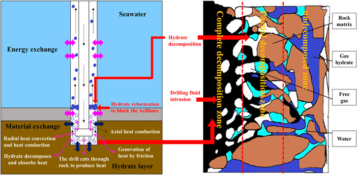
FIGURE 2. Drilling fluid invasion profile around the wellbore. The boundary and distance between zones do not represent the actual boundary and distance.
The drilling fluid profile reveals that when the drilling fluid penetrates the reservoir, the properties of the hydrate-bearing sediments will change due to the composition of the drilling fluid and the dissociation of gas hydrate. The drilling fluid and gas hydrate dissociation will affect the mechanical characteristics, electrical properties, thermal properties, and permeability of the formation near the wellbore, affecting the geomechanical stability of the formation, the reliability of resistivity logging during drilling, and the heat transfer, gas production rate of subsequent production (Ning et al., 2014). These situations were encountered during the Gulf of Mexico Gas Hydrate Joint Industry Project Leg II (JIP Leg II) when drilling the well WR 313 (Collett et al., 2009; Cook et al., 2012). The phase change of gas hydrate is one of the primary characteristics of drilling fluid invasion into hydrate formation, which is also the main difference between drilling fluid invasion into hydrate formation and conventional oil and gas formation. This process is actually a coupling of the temperature field, seepage field, stress field, and chemical field (Teymouri et al., 2020; Ruan et al., 2021). Advanced numerical simulators can be used to solve the coupled thermo-hydro-mechanical-chemical (THMC) process during the interaction process between drilling fluid and hydrate reservoir (Bai et al., 2021; Bai et al., 2022; Samala and Chaudhuri, 2022). Therefore, the establishment and solution of highly nonlinear and coupled differential equations with great challenges is one of the research hotspots in this field.
The micro overbalance drilling method is generally adopted for drilling hydrate wells, that is, maintaining the pressure in the hole slightly greater than the formation pore pressure and less than the formation fracture pressure to prevent the wellbore instability caused by the dissociation of gas hydrate and methane overflow. The wellbore instability is generally manifested as fracture, collapse (diameter expansion), and diameter reduction. During drilling, the positive pressure difference will cause the drilling fluid filtrate to penetrate into the borehole wall rock, and the pore pressure, temperature, salt content, and water content will increase accordingly (Ning, 2005; Ning et al., 2013). The increase of formation temperature leads to the thermal dissociation of gas hydrates near the wellbore. The dissociation of gas hydrates increases the formation pore pressure and water content. At the same time, the mud and sand particles cemented by gas hydrate collapse, which sharply reduces the mechanical strength of wall rock (Ning et al., 2009; Ning et al., 2013). Drilling fluid invasion and hydrate dissociation will alter pore pressure, pore fluid flow, and hydrate dissociation rate. The effective stress of the wellbore framework and the crushing resistance of the wellbore decrease as the formation pore pressure rises. For fine-grained and soft hydrate sediments, the invasion of drilling mud and the dissociation of gas hydrate may result in the fracturing of hydrate sediments. If the gas produced by dissociation enters the wellbore, it will lead to drilling fluid gasification (Fereidounpour and Vatani, 2014). The water and gas produced by dissociation will not only further increase the water content near the well wall, but also the dissociation of hydrate will improve the formation permeability and increase the invasion rate of drilling fluid, which is not conducive to the formation of filter cake to protect the well wall. Therefore, the process from the opening of the wellbore to the complete dissociation of gas hydrate near the wellbore is the most unstable stage of the wellbore. At the same time, the ions in the drilling fluid intrude into the formation with the filtrate, and ion exchange occurs at the borehole wall. Chemical potential increases the migration and permeability of the filtrate as well as the water dialysis under the capillary force. The multi factor coupling action accelerates the hydration reaction of the argillaceous hydrate reservoir while drastically lowering the mechanical strength of the wall rock. In addition, the heat generated by the friction between the circulating drilling fluid and the wellbore and the drilling tool, the heat generated by the friction between the drilling tool and the wellbore during the up and down movement and the rotation of the drilling tool will increase the temperature around the wellbore and continuously decompose the gas hydrate. The up and down movement of drilling tools will also cause the continual change of bottom hole pressure, resulting in the invasion of drilling fluid and the instability of the wellbore. Because gas hydrates usually occur in the semi-consolidated or even unconsolidated mud and sand layer on the seabed, and the water depth is so large, borehole collapse or fracture will happen more easily than in a typical oil and gas reservoir.
3 Materials and methods
3.1 Soil and sand sample properties
It is generally believed that gas hydrate sediments should be tested in situ. However, due to the high cost and technical difficulty of in-situ sampling of marine natural gas hydrate, it is necessary to formulate a reasonable and scientific artificial core preparation scheme (Song et al., 2014). The first thing to consider in manual sample preparation is the nature of the sediment. The size, shape, and composition of sediment grains affect the nucleation and growth of gas hydrate. Field exploration and in-situ drilling coring found that hydrate saturation increased with the increase of pore volume ratio and particle size (Ito et al., 2015) and it is known that gas hydrate is preferentially accumulated in coarse sand (viz., sandy; mean > 63 μm) (Su et al., 2021). The coring analysis in the east of the Nankai Trough in Japan also verifies a significant positive correlation between gas hydrate saturation and sand content and median particle size (Ito et al., 2015). According to Shepard and Moore (Shepard and Moore, 1954; Kuang et al., 2019) and the sediment particle size standard determined by the geotechnical code, the hydrate-bearing sediment samples from the Krishna Godavari, Mahanadi, and Andaman basins in India are mainly composed of clay and silt particles, with a median grain size of 1.86–186 μm (Guo et al., 2020; Maiti et al., 2022). The gas hydrate drilling cores in the gas hydrate reservoir in the South China Sea are mainly silt and clay. The grain sizes of hydrate-bearing sediment samples are primarily distributed in the range of 0.2–200 μm (Guo et al., 2020; Zhu et al., 2020). The median grain size of sediments in the eastern Nankai Trough of Japan is 4.0–146.4 μm (Kuang et al., 2019). The hydrate-bearing sediment cores obtained from the Hydrate Ridge in the Pacific Ocean (ODP204 voyage) show that gas hydrates mainly occur in 8–26 μm and 50–148 μm of the sediment (Su et al., 2005). Sand and clay minerals were proportionally blended in this investigation to create artificial samples (Luo et al., 2016; Shen et al., 2022).
To imitate the muddy sandy hydrate reservoir, a mixture of kaolin (0–50 μm) and quartz sand (150–230 μm) was utilized. Sand materials with different grain sizes were observed through a microscope made by Olympus Corporation, as shown in Figure 3. Commercial sand and clay minerals used to prepare artificial samples were purchased from Perfemiker. So far, most of the recovered natural gas hydrate samples are sI methane hydrate. Therefore, methane hydrate with different saturation in sediments has been studied. Methane gas was purchased from Huate Gas Co., Ltd. with a purity of 99.9%. The distilled water for the experiment is from Guangzhou Yafei water treatment equipment Co., Ltd., with conductivity ≤0.1 μs/cm. See Table 2 for specific information of experimental materials. The authors indicated the feasibility of the artificial samples by comparing the mechanical properties of the artificial samples with those of Luo et al. (2016), Li L et al. (2021), Shen et al. (2022).
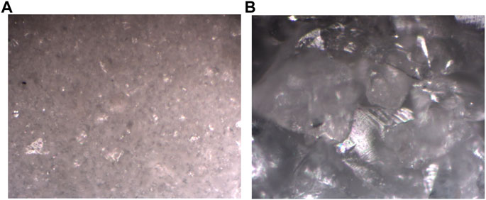
FIGURE 3. Image of soil and sand sample observed under the microscope. (A) kaolin (0–50 μm), (B) quartz sand (150–230 μm).
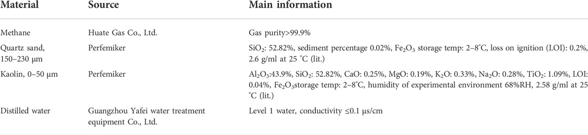
TABLE 2. Information of experimental materials for hydrate-bearing sediments.
3.2 Drilling fluid properties
It is critical to avoid drilling fluid invading the reservoir during deepwater drilling and hydrate development since this poses a severe danger to safe and effective drilling. Hydrate reservoir drilling now uses water-based, oil-based, and synthetic-based drilling fluids. The oil-based drilling fluid, such as the production test well of Ignik Sikimu oil field in the United States, has been selected for the hydrate drilling activities in the frozen soil area, because of its good hydrate control performance and anti-freezing performance (Grigg and Lynes, 1992; Schoderbek et al., 2013). However, when all factors such as hydrate inhibition, environmental protection, and cost are taken into account, the water-based drilling fluid system is still the best option for natural gas hydrate exploration (Liu et al., 2016). The sepiolite mud, lecithin-water solution drilling fluid, KCl polymer drilling fluid, and other drilling fluids that are conducive to safe solid carrying and good hydrate inhibition are selected in the hydrate drilling activities in the waters around India, the Mallik permafrost region, the Gulf of Mexico, and the Nankai Trough of Japan (Burger et al., 2006; Collett et al., 2012; Merey, 2016). Therefore, the water-based drilling fluid in this investigation had 10% ethylene glycol, 0.5% lecithin, and 0.5% polyvinylpyrrolidone (PVP) added to it. The drilling fluid is provided by the China University of Petroleum (East China), and the particular formula is protected by intellectual property rights, thus it is not practical to go into detail.
The experimental performance test of drilling fluid shows that the apparent viscosity (AV) of the drilling fluid is 41.5 mPa·s, the plastic viscosity (PV) is 29.0 mPa·s, the yield point (YP) is 13.5 Pa, and the ratio of yield point to plastic viscosity (YP/PV) is 0.47 at 25°C. AV, PV, YP, and YP/PV of drilling fluid at 4°C are 49.0 mPa·s, 34.5 mPa·s, 16.5 Pa, and 0.48 respectively. YP (4°C)/YP (25°C) = 1.22. It can be seen that the viscosity of the drilling fluid increases little at low temperatures, which can reduce the problem of lost circulation caused by serious thickening at low temperatures. The drilling fluid can effectively break rock at a high shear rate and carry rock cuttings at a low shear rate, to purify the bottom of the borehole and ensure wellbore stability. The filtrate loss of drilling fluid is 5.2 ml under normal atmospheric temperature, a pressure difference of 690 kPa, and a test time of 30 min. The filter cake is thin and tough, with a weak sand feeling, good smoothness, no looseness after soaking, and good firmness. After the mud cake in the downhole environment is compacted under the pressure difference, it will effectively stabilize and protect the open hole wall. It is speculated that the wall-building property of the drilling fluid is good.
3.3 Apparatus
The experiment adopts the experimental system developed by Southwest Petroleum University, as shown in Figure 4. The advantage of the device is that the gas hydrate generation experiment and triaxial mechanical test can be completed in the same reactor, which can effectively avoid the dissociation of gas hydrate in the test process. The experimental device includes a reactor, a temperature regulation system, a pressure regulation system, a triaxial mechanics system, a fluid control system, an acoustic and electrical measurement system, and a data acquisition and control system. The reactor is where gas hydrate sediments are created and the sand that represents a reservoir is squeezed into cylinder cores. The sidewall of the inner chamber of the reactor is a black cylindrical rubber cylinder (see Figure 5A). The inside of the reactor is sealed by the rubber cylinder, the upper steel cover, and the lower steel shaft (see Figure 5B) without air leakage. The upper steel cover is provided with a high-pressure resistant visual window, through which one can observe the image in the reactor in real-time through the equipped high-definition camera. The working pressure range of the reactor is 0–35 MPa, and the temperature range is -6–25°C. The temperature regulation system is mainly composed of cooling jackets, two NVOHAI THD-0506 refrigeration units, and supporting refrigeration pipelines. Industrial alcohol is used to reduce the freezing point of water in the water bath device, and to maintain the low-temperature environment inside the reactor and the drilling fluid tank. The reactor and drilling fluid tank are wrapped with a layer of insulation sleeves to avoid heat exchange with the environment. The pressure regulation system includes a gas pressure regulation unit, a confining pressure regulation unit, and an axial pressure regulation unit. Here we refer to the gas pressure regulation unit in particular. The pressure of gas and the pore pressure of gas hydrate sediments are regulated by the gas pressure regulation unit, which is mainly composed of gas injection pipelines, gas pressure regulating valves, and a gas cylinder. The confining pressure regulation unit and the axial pressure regulation unit form part of the triaxial mechanical system. The other part of the triaxial mechanical system mainly includes the loading instrument, the displacement gauge, stress sensor, etc. The system controls the confining pressure and axial pressure in the reactor through the loading instrument, which can provide necessary pressure conditions for the initial preparation of natural gas hydrate, and also provide a guarantee for the determination of mechanical parameters in the later stage of the experiment. The fluid control system includes a gas control unit (i.e., gas pressure regulation unit), a seawater control unit, and a drilling fluid control unit. It is mainly composed of a vacuum pump, two gas cylinder, two gas stabilized pressure pump, a buffer tank, a water tank, a liquid injection pump, and a drilling fluid tank. The acoustic and electrical measurement system includes acoustic wave and resistivity test units. The acoustic wave is transmitted and received by the acoustic probe and displayed on the DS1052E oscilloscope. The resistivity of the hydrate-bearing core is measured by the TH2810B bridge instrument. The data acquisition and control system controls the experimental parameters by computer and records the experimental data and images.
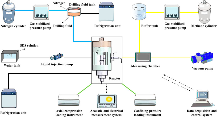
FIGURE 4. Schematic of the experimental system.
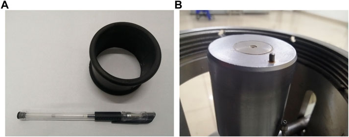
FIGURE 5. The rubber cylinder (A) and lower steel shaft (B) of gas hydrate reactor. The diameter of the rubber cylinder is 60 mm, and the size of the internal space of the reactor can be reduced with the compression of the lower steel shaft.
The experimental device is equipped with pressure sensors with an accuracy of ±0.2% of full scale and a range of 0–40 MPa to measure the gas pressure in the reactor and pipeline, and temperature sensors with an accuracy of ±0.05% of full scale and a range of −50 to 150°C to measure the temperature in the reactor and drilling fluid tank. The parameter monitoring instruments of the experimental device also include an XMT instrument cabinet, a high-voltage ultra-clear monitoring camera, and a measuring chamber.
3.4 Experiment procedures
The reservoir lithology of gas hydrate in the deep sea is mainly divided into consolidated diagenetic hydrate and weakly cemented non-diagenetic hydrate. The non-diagenetic gas hydrate is difficult to support the reservoir under external temperature and pressure disturbance due to poor rock and soil cementation in the reservoir. The generation of gas hydrate will enhance the strength of the reservoir, while the decomposed hydrate-bearing sediments is prone to deformation. The weakly cemented sandy samples used in the experimental test are prepared from quartz sand and kaolin (clay). The mass ratio of quartz sand to kaolin in the sample is 0.9:0.1. The quality of soil and sand is 100 g. The weak cemented gas hydrate sample is prepared by the simple quartz sand filling method. The temperature and pressure of the hydrate reservoir are first simulated, and then the triaxial tests of hydrate-bearing sediment are carried out using the prepared samples. The effects of drilling fluid invasion on the strength behaviors of hydrate-bearing sediments are then studied, and changes in mechanical characteristic parameters of hydrate-bearing sediments are observed. The experimental flow of gas hydrate-bearing sediment preparation is shown in Figure 6 and the experiment procedures are as follows.

FIGURE 6. The experimental flow of gas hydrate-bearing sediment preparation.
3.4.1 Step 1: Sample preparation
The selected quartz sand and kaolin are mixed evenly according to the specified ratio, and the bottom and side parts of the sample are wrapped with a thin rubber film before being loaded into the rubber cylinder of the reactor. Cover the reaction chamber with the upper steel cover, secure the upper steel cover and the reactor, and then compact the sand by loading 10 MPa axial pressure on the reactor according to the experimental requirements. The rock sample can be molded into unconsolidated reservoir frameworks depending on the compaction and cementation. Vacuum pumping is essential to prevent the influence of air in the reactor on the natural gas hydrate preparation process. The temperature in the reactor can be controlled by turning on the temperature regulation system for refrigeration. Then inject quantitative sodium dodecyl sulfate (SDS) solution into the cylindrical porous rock sample in the reactor under appropriate temperature conditions. The mass concentration of SDS solution is 0.03%, which is used to promote the rapid generation of methane hydrate (Wu and Zhang, 2009). After the water is fully penetrated, the gas pressure regulation unit is started to pressurize to keep the pressure in the reactor at the predetermined hydrate generation pressure. When the consumption rate of natural gas is zero, it indicates that methane hydrate has been formed. The prepared hydrate-bearing sediment is used for subsequent mechanical tests. The preparation process of hydrate-bearing sediment is shown in Figure 4. It should be noted that in order to balance the air pressure in the rubber cylinder, it is necessary to keep the confining pressure slightly higher than the internal air pressure in the reactor to maintain the stable shape of the sample.
3.4.2 Step 2: Triaxial tests
The required parameters are set for the conventional triaxial tests after the hydrate-bearing sediment samples with a certain saturation are prepared according to the method described in step 1. The three stresses applied to the cylindrical sample (σ1, σ2, and σ3) are perpendicular to each other, two of which are equal, i.e., the medium principal stress is equal to the minor principal stress (σ2 = σ3). △σ, indicates the deviator stress, which is equal to the difference between axial stress and radial stress (△σ=σ1−σ2). During the experiments, the operator increases the axial stress and radial confining pressure of the hydrate-bearing sediment sample to the specified confining pressure equivalently (the effective confining pressure is 3 MPa), then keeps the confining pressure unchanged, and continues to increase the axial stress of the sample. The loading speed of the axial load is 0.2 mm/min. The displacement caused by radial and axial deformation of the sample is collected and recorded in the data acquisition and control system. After the experiment, remove the internal air pressure, confining pressure and axial load in sequence. Finally, open the upper steel cover of the reactor and take out the sample.
3.4.3 Step 3: Drilling fluid invasion
Clean up the reactor after the triaxial test, and re-prepare hydrate-bearing sediments with hydrate saturations of A1 to A4 as directed in step 1. The drilling fluid is sucked from the drilling fluid tank into the pipeline using the negative pressure in the pipeline. Then increase the nitrogen pressure through the gas stabilized pressure pump. After the gas pressure rises to the invasion pressure, open the control valve between the drilling fluid injection pipeline and the reactor to inject the hydrate-bearing sediment from the top of the reactor with the drilling fluid at different temperatures at a pressure of 12 MPa. When the invasion time reaches the preset value, the triaxial experiment can be started. The operation process of the triaxial test shall be carried out in strict accordance with the method described in step 2. Although the sample preparation may deviate from the actual value of hydrate saturation under the same conditions, the inevitable random error is acceptable because the experimenters scrupulously follow the same criteria and methods.
3.5 Methane hydrate saturation
At present, the main methods for preparing hydrate-bearing sediment samples include the ice searching method, excess gas method, excess water method, and dissolved gas method (Lijith et al., 2019; Chen et al., 2022). In this study, we choose the excess gas method to make the methane hydrate. The excess gas method entails keeping a certain amount of water in the pores of a rock sample and injecting excess gas under appropriate temperature and pressure conditions to convert all of the water molecules in the pores into structural water molecules of gas hydrate, resulting in the desired hydrate saturation. Under the temperature and pressure conditions in this paper, water will not exist in the form of ice, so the hydrate saturation obtained by this method is accurate and reasonable. Hydrate saturation is a key parameter for reservoir optimization and resource evaluation. The precise computation of hydrate saturation is critical for determining the mechanical properties of the hydrate reservoir under drilling fluid invasion. According to the chemical reaction formula for producing methane hydrate, 1 mol of methane and 5.75 mol of water will be consumed for each 1 mol of methane hydrate generated. Therefore, the water consumed to produce hydrate sediments with specific hydrate saturation can be calculated by the Eq. 1 (Li et al., 2017). Since the concentration of SDS solution is very low, the influence of solute molecules on the quality of water consumed can be ignored. However, about 5% of the excess SDS solution was still added to offset the inevitable loss of water during the experiment. Experiments have validated this strategy, thus it is regarded as reasonable. The verification method of actual saturation during the experiment is shown in Eq. 2 (Shen et al., 2022).
where
The mechanical test of hydrate-bearing sediments without drilling fluid invasion was carried out and then the drilling fluid invasion experiment was carried out when the simulated reservoir temperature and pore pressure were constant. The hydrate saturation range of this study is roughly controlled at 5%–35%. The reservoir temperature has two options of 4 and 8°C, and the in-situ pore pressure has two grades of 10 and 12 MPa. There are three choices of drilling fluid temperature, and two levels of invasion time, with a total of 24 groups of drilling fluid invasion experiments. Note that the equilibrium temperatures of the methane hydrate at 10 and 12 MPa when the triaxial shear test is performed are 13.47 and 15.12°C, respectively, according to the CSMHyd software. The experimental conditions and parameter settings are shown in Tables 3, 4.
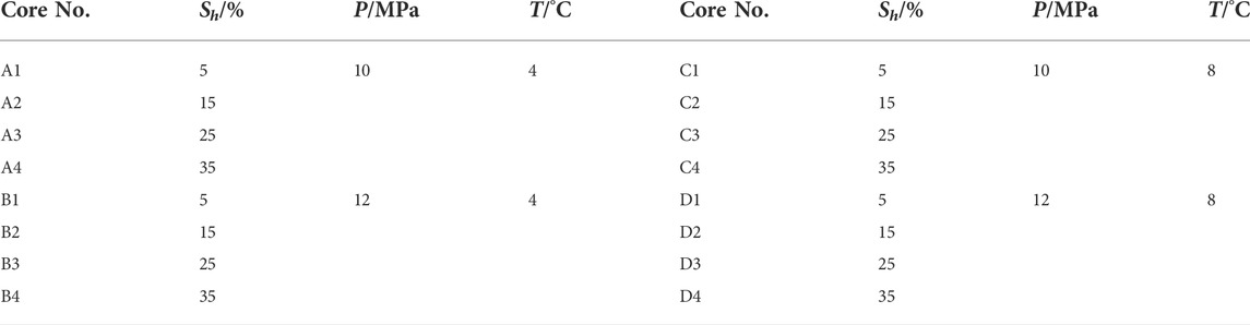
TABLE 3. The experimental conditions for the preparation and mechanical test of hydrate-bearing sediments in the non-intrusive state. Sh represents the hydrate saturation, P and T represent the pressure and temperature in the reactor respectively.
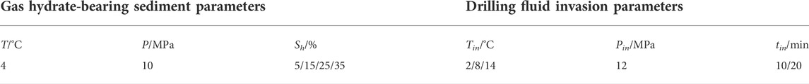
TABLE 4. The experimental conditions for the mechanical test of hydrate-bearing sediments in the intrusive state. Tin and Pin represent the drilling fluid temperature and invasion pressure respectively, and tin represent the invasion time.
4 Results and discussion
4.1 Effect of temperature, pressure, and hydrate saturation on stress-strain behaviors
Temperature, pressure, and hydrate saturation all affect the strength behaviors of hydrate-bearing sediments, according to the mechanism. Figure 7 shows the experimental phenomena observed by the camera before and after hydrate generation under reservoir temperature of 4°C and pore pressure of 12 MPa. The filter screen in Figure 7 is primarily used to prevent mud and sand from leaking and obstructing gas and liquid pipelines, and it has no bearing on the mechanical properties. The stress-strain relationship of hydrate sediments provides the foundation for evaluating reservoir strength parameters and deformation features in the development of gas hydrate resources. 16 groups of experiments were conducted under different temperatures, pressures, and hydrate saturation conditions, and the stress-strain curves under the effective confining pressure of 3 MPa were obtained, as shown in Figure 8. It is noticeable that as the load increases, the sediment deforms and eventually fails. The stress-strain law of hydrate sediments exhibits a trend of transition from strain hardening to strain softening with an increase in hydrate saturation from 5% to 35%, regardless of the temperature and pressure conditions of the environment in which methane hydrate is found. The stress-strain curves of hydrate-bearing sediments have no clear peak points when the hydrate saturation is between 5% and 15%, and they all show the characteristics of strain hardening. The failure characteristics of the sandy sediments with low hydrate saturation can be demonstrated to constitute ductile failure in this investigation. When the hydrate saturation is between 25% and 35%, the stress-strain curves of hydrate sediments show obvious peak points, which are characterized by strain softening. It can be seen from the figure that the peak strength of the strain softened sediments occurs near the strain equal to 1%–2%. When the strain range is less than 1%, the higher the hydrate saturation is, the faster the deviator stress of the hydrate-bearing sediment increases. According to the experimental results, the critical hydrate saturation value of hydrate-bearing sediments for strain hardening and strain softening transition is between 15% and 25%. This result is consistent with the conclusion of Masui et al. (2006), Masui et al. (2008), Zhang et al. (2018).
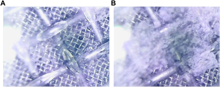
FIGURE 7. Experimental phenomena were observed in the reactor before and after hydrate generation. (A) Pre-experiment phenomenon; (B) Post-experiment phenomenon.
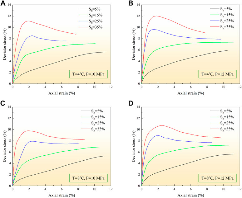
FIGURE 8. Stress strain curves at different temperatures and pressures. (A) The stress-strain curve under reservoir temperature of 4°C and pore pressure of 10 MPa. (B) The stress-strain curve under reservoir temperature of 4°C and pore pressure of 12 MPa. (C) The stress-strain curve under reservoir temperature of 8°C and pore pressure of 10 MPa. (D) The stress-strain curve under reservoir temperature of 8°C and pore pressure of 12 MPa.
The peak strength of strain hardened hydrate deposits is defined as the deviator stress at 8% strain. For the hydrate-bearing sediments with strain softening, the peak strength is equal to the value of the highest point of the stress-strain curve. The relationship between peak strength and hydrate saturation is shown in Figure 9. It can be found that with the increase of hydrate saturation, the deviator stress of hydrate-bearing sediments increases, and the stiffness and strength increase significantly. It can be seen from Figures 8, 9 that the strength of hydrate-bearing sediments increases with the decrease of reservoir temperature. This is mainly because the strength of solid hydrate in the pore space increases with the decrease of temperature, further strengthening the cementation between particles (Hyodo et al., 2002). Moreover, Figure 8 also reveals that within the pressure range studied in this study, the strength of hydrate-bearing sediments increases with the increase of pore pressure.
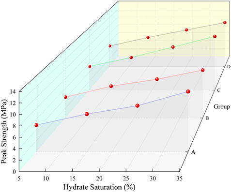
FIGURE 9. The peak strengths of the hydrate-bearing sediments increase with the increase of hydrate saturation.
Studies have shown that the mechanical properties of hydrate-bearing sediments mainly depend on the morphology of gas hydrate in pores. Hydrate-bearing sediments show better geomechanical properties, which is the reason for their greater stability as compared to the native sediments. Therefore, if the dissociation of gas hydrate in the reservoir can be controlled, the formation with high hydrate saturation is less prone to borehole collapse than the formation with low hydrate saturation (Zhang et al., 2017). For coarse-grained sandy sediments, with the increase of hydrate saturation, the hydrate occurrence in the pores transits from pore filling type, and load-bearing type to grain cementing type (Lijith et al., 2019). According to Lijith et al. (2019) the hydrate saturation at which a sudden increase in effective cohesion is observed is defined as breakpoint hydrate saturation (SHB). When the hydrate saturation is 0, the stress increases with the axial strain, and the sample shrinks and becomes dense gradually. When the hydrate saturation is between 0 and SHB, the hydrate growing in pores and on surfaces of rock grains will hinder the rolling and sliding between grains under external forces. These broken, falling, or crushed hydrates will lead to the expansion of hydrate-bearing sediments and the increase of residual shear strength. When the hydrate saturation is greater than SHB, the hydrate cementation between grains is stronger. At this moment, hydrate saturation has a significant impact on the effective cohesion of hydrate-bearing sediments. This phenomenon is closely related to hydrate growth around rock grains. During the shear process of the samples, the failure plane may extend along with the hydrate or sediment-hydrate boundary, which may eventually lead to the strain softening of hydrate-bearing sediments.
The research shows that under the condition of low hydrate saturation, the relationship between stress-strain behaviors of hydrate-bearing sediments is limited by temperature (Shen et al., 2022), which can be seen from the stress-strain curves with the hydrate saturation of 5% and 15%. When the hydrate saturation is high, the effect of hydrate cementation on the mechanical properties of hydrate-bearing sediment samples is more obvious. The influence of pressure, on the other hand, is stated as follows: the strength of methane hydrate increases as pressure rises, and the change in hydrate crystal strength further affects the cementation strength of hydrate-bearing sediments (Hyodo et al., 2013; Jiang et al., 2015; Shen et al., 2021). This is the conclusion for the stable region of hydrate phase equilibrium. If the temperature and pressure conditions exceed the stable region and the gas hydrate continues to decompose, the stress-strain behavior will be seriously affected. Actually, the mechanical properties of geotechnical materials are inevitably influenced by numerous factors. In addition to the experimental conditions studied in this investigation, the factors that change the stress-strain behaviors of hydrate-bearing sediments also include confining pressure, grain size, porosity, microstructural aspects of soils, etc. (Hyodo et al., 2013; Jiang et al., 2015; Wang et al., 2020; Bai et al., 2021; Shen et al., 2021). We have also seen a surge in research into the thermal, hydraulic, and chemical action processes that affect the stress state variables of hydrate-bearing sediments in recent years (Li Y et al., 2021; Samala and Chaudhuri, 2022; Wang et al., 2022). Accordingly, the further work in this study will include the analysis of the coupling action of multiple fields on the mechanical properties of gas hydrate reservoirs.
4.2 Effects of drilling fluid temperature and invasion time on stress-strain behaviors
External disturbance, which is usually bad, will change the mechanical properties of hydrate-bearing sediments. For example, the increase of ocean temperature caused by global warming leads to the dissociation of hydrate and the escape of gas, causing reservoir stability to deteriorate. Long term field test may lead to reservoir instability, which may lead to geological disasters such as earthquake, tsunami and collapse (Merey, 2016; Wang et al., 2020). When the bit is drilled to the hydrate layer in drilling activities, the drilling fluid continuously infiltrates into the reservoir, driven by the pressure difference between the bottom hole and the formation, causing changes in hydrate saturation, pore pressure, temperature distribution, and physical and mechanical properties. To investigate the strength behaviors of drilling fluid invading hydrate-bearing sediments, we conducted laboratory tests with drilling fluid developed by China University of Petroleum (East China). Based on the experimental data of hydrate-bearing sediments with four hydrate saturations of A1–A4 without drilling fluid invasion, we carried out 24 groups of drilling fluid invasion experiments. The pressure difference between the drilling fluid and the pore pressure is 2 MPa, the drilling fluid temperature is 2, 8, and 14°C respectively, and the invasion time is 0.5 h and 1 h.
Figures 10, 11 respectively show the changes in stress-strain curves and peak strengths of hydrate-bearing sediments after drilling fluid invasion with different hydrate saturation, drilling fluid temperature, and invasion time. The experiment reveals that the invasion of drilling fluid does not change the trend of hydrate-bearing sediment strength increasing as saturation increases. When the hydrate saturation is low, the influence of drilling fluid invasion on the stress-strain curve is small. The trend of weakening the strength properties of sediments seems to increase with the increase of hydrate saturation. In the case of high hydrate saturation, with the increase of drilling fluid invasion time, the sediment shows a trend from brittle failure to ductile failure. The peak strength of hydrate-bearing sediments decreased, with a maximum reduction of 47.71% and a minimum decrease of 7.02%. In this study, the top of the core sample is the first to come into contact with the drilling fluid, so the deformation of the sediment may first occur at the contact interface, similar to the diffusion of drilling fluid from the wellbore to the reservoir shown in Figure 2. The small size of the core sample may explain why the strength of the hydrate-bearing sediment decreased in such a short period. When the hydrate saturation and the intrusive pressure difference are the same, the temperature is the main factor driving this process. It can be seen from Figures 10, 11 that the strength of hydrate-bearing sediments becomes weaker with the increase of drilling fluid temperature or invasion time. This is mainly because the increase in temperature accelerates the hydrate dissociation process, and then the strength of the hydrate-bearing sediment decreases. The higher the temperature of the drilling fluid, the more likely the gas hydrates are to slide, dislocate, fragment, and fall off under the action of triaxial stress. If the temperature of the interface between drilling fluid and hydrate increases and exceeds the phase equilibrium region, the gas hydrate will decompose rapidly due to the increase in drilling fluid temperature. The gas produced by hydrate dissociation will increase the pore pressure, and the water produced by hydrate dissociation will increase the water saturation. If the sediment contains clay minerals, the reservoir permeability will be lower due to hydration expansion. All these factors will affect the stress-strain curve of hydrate-bearing sediments. It should be noted that even if the drilling fluid temperature is lower than the reservoir temperature, the drilling fluid will cause a change in reservoir strength properties. First of all, the drilling fluid is a complex dispersion system containing a variety of chemicals, including salts, alcohols, and other substances that will change the phase equilibrium curve, thus affecting the stability of the gas hydrate. Secondly, the hydration of water-based drilling fluid will change the rock structure microscopically, and macroscopically, and reduce the cohesion of rock and soil. This complex multi-field coupled process has been verified in some experimental and numerical simulations (Gao et al., 2019; Liao et al., 2021).
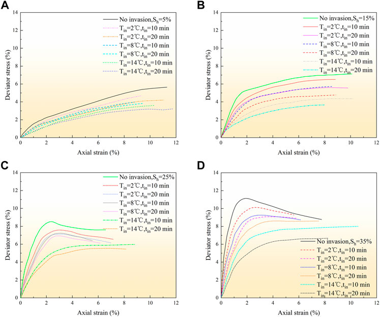
FIGURE 10. Stress‐strain curve of hydrate‐bearing sediment after drilling fluid invasion. (A) The stress-strain curve with 5% hydrate saturation. (B) The stress‐strain curve with 15% hydrate saturation. (C) The stress-strain curve with 25% hydrate saturation. (D) The stress-strain curve with 35% hydrate saturation.
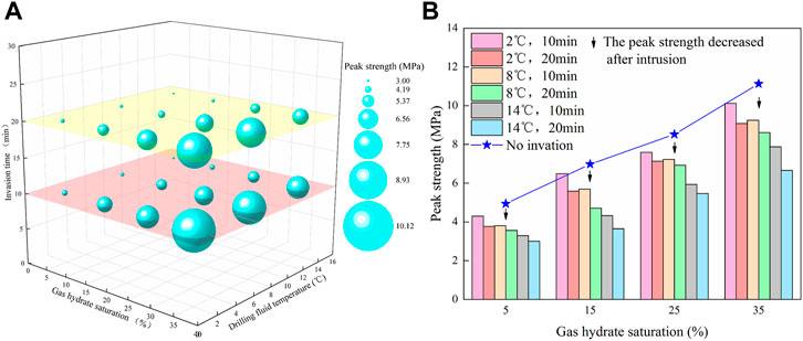
FIGURE 11. The peak strengths of hydrate-bearing sediments after drilling fluid invasion vary with hydrate saturation, drilling fluid temperature, and invasion time. (A) The peak strengths of the hydrate-bearing sediments are expressed in terms of bubble size. (B) Peak strength variations before and after drilling fluid invasion.
4.3 Effects of drilling fluid invasion on other mechanical properties
Figure 12 shows the changes in Poisson’s ratio (
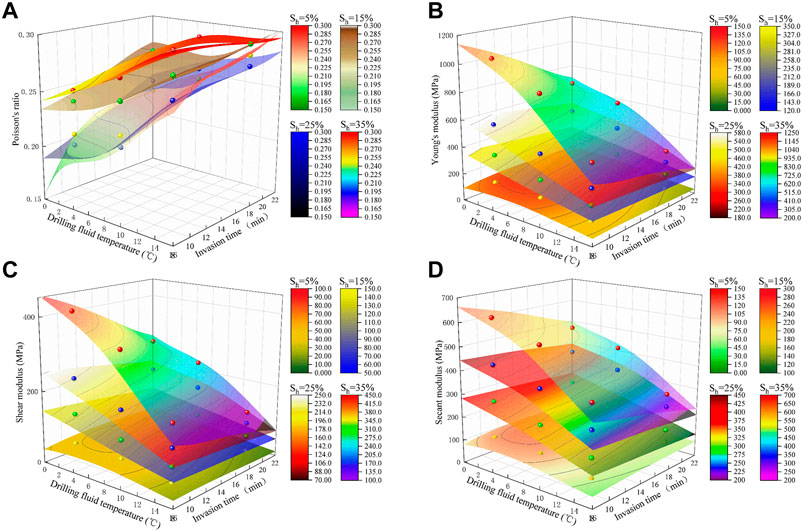
FIGURE 12. Changes of mechanical parameters before and after drilling fluid invasion. (A) Poisson‘s ratio, (B) Young‘s modulus, (C) shear modulus, and (D)secant modulus.
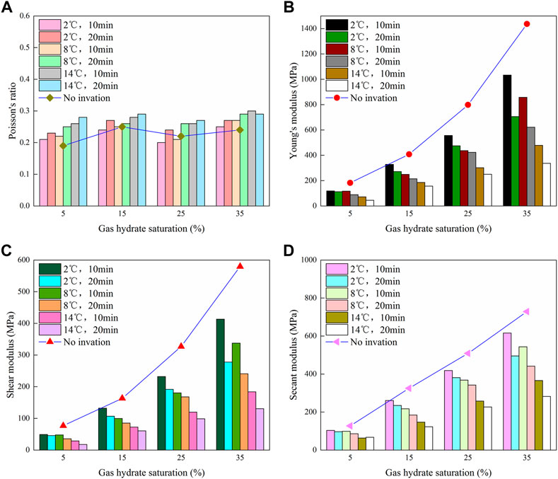
FIGURE 13. Changes of mechanical parameters before and after drilling fluid invasion. (A) Poisson’s ratio, (B) Young’s modulus, (C) shear modulus, and (D) secant modulus.
The various moduli of materials refer to the ratio of stress to strain under force. Corresponding to different stress states, there are different names. The elastic-plastic or plastic deformation characteristics of hydrate-bearing sediments with low hydrate saturation cannot be simply characterized by elastic modulus and other parameters. Since the stress-strain curves have been described, additional analysis is helpful to reveal the impact of drilling fluid invasion on the reservoir. It is considered that the initial stage of hydrate sediment deformation meets the characteristics of elastic deformation in this investigation.
4.4 Suggestions for future research
Driven by the pressure difference between the bottom hole and the formation, the drilling fluid filtrate continuously seeps into the reservoir during the drilling fluid invasion. In addition to fluid migration and material transfer, there are also changes in temperature, pressure, and pore water salinity. The change in salinity will cause the deviation of the hydrate phase equilibrium curve, and the change in temperature and pressure will cause the dissociation of gas hydrate. In summary, the interaction between drilling fluid with a given salinity and inhibitor content and the hydrate reservoir is mostly produced by permeability induced by pressure differences and hydrate dissociation caused by temperature differences. These two factors can have a strong impact on the spatial distribution of physical parameters, thus changing the stress distribution of the wall rock of the wellbore. As a consequence, whether in the calculation of the wall rock stress or during the experimentation phase, it is vital to investigate the impact of these two parameters on the stress field of the wellbore. In view of this, the goal of engineering measures is to reduce changes in in-situ temperature and pressure to prevent the dissociation of gas hydrate and risks such as wellbore instability and reservoir collapse. Some recommendations below for future research are made in this paper.
➢ Micro overbalance drilling is recommended.
➢ Drilling fluid with strong hydrate inhibition performance shall be used.
➢ The temperature of the drilling fluid must be reduced.
➢ Reduce the filtration loss of the drilling fluid.
➢ It is suggested to increase the density of the drilling fluid.
➢ Risk monitoring measures are essential.
At present, the study on a specific drilling fluid system for hydrate drilling is still in its early stages, and the low-temperature drilling fluid system with strong hydrate inhibition and plugging property based on deep-water drilling fluid is likely to become the main focus in the future. Theoretical work on the wellbore stability of gas hydrate under the influence of the drilling fluid is now underway. However, most of these studies focus on the construction of wellbore stability models and software coupling simulations. There are few field application technologies, so field experiments and applications should be increased. In addition, bottom-hole temperature and pressure management technology to prevent hydrate dissociation and promote hydrate regeneration could be the key to resolving the problem of safe drilling and production in hydrate reservoirs. And confining pressure is another important factor affecting wellbore stability. It is suggested to conduct experiments under different confining pressures to explore the changes in parameters such as cohesion, internal friction angle, and expansion angle of hydrate-bearing sediments after drilling fluid invasion.
5 Conclusion
We have studied the effect of drilling fluid invasion on the strength behaviors of hydrate-bearing sediments. To accomplish this, the mechanical properties of hydrate-bearing sediments with different hydrate saturations under constant pressure differences were simulated by changing the drilling fluid temperature and invasion time. Compared with native sediments without gas hydrates, hydrate-bearing sediments show better geomechanical properties. The increase in hydrate saturation can significantly enhance cementation, making its impact on the mechanical properties of sediment samples more obvious. These mechanical properties make it more stable. Our research has shown that the peak strengths of the hydrate-bearing sediment samples increase with increasing hydrate saturation and pressure and decrease with increasing temperature. As the hydrate saturation increases from 5% to 35%, the hydrate-bearing sediments change from strain hardening to strain softening, and the critical hydrate saturation value of the transition is between 15% and 25%. In the hydrate dissociation zone, drilling fluid invasion will change the elastic parameters and strength parameters of the sediment, resulting in poor wellbore stability. With the increase in drilling fluid temperature and invasion time, the peak strength, Young’s modulus, shear modulus, and secant modulus decrease, while Poisson’s ratio increases. The stress field around the well will be reallocated due to the hydrate dissociation process and the fluid-solid coupling effect. Our study has also shown that the influence of drilling fluid invasion on the mechanical parameters of the wall rock is usually ignored in the design of drilling fluid. Given the risks of drilling fluid invasion and hydrate dissociation in drilling activities, research on drilling fluid invasion mechanisms and performance optimization will help to prevent hydrate dissociation and avoid risks such as wellbore instability and reservoir collapse.
Data availability statement
The original contributions presented in the study are included in the article/supplementary material, further inquiries can be directed to the corresponding authors.
Author contributions
JP: Investigation, methodology, experiment, writing—original draft, review and editing. NW: Investigation, writing—review, supervision, funding acquisition. BZ: Methodology, data curation, experiment, visualization. JZ: Conceptualization, investigation, review. BK: Methodology, investigation, review. RC: Investigation, review. HL: Validation, resources, experiment. RB: Formal analysis, experiment.
Funding
This work was financially supported by the National Natural Science Foundation of China (U20B6005-05, 51874252), National Key Research and Development Program of China (2021YFC2800903), Sichuan High-end Foreign Talent Introduction Project (SYZ202124), High-end Foreign Experts Recruitment Plan of China (G2021036005L), 111 Project (D21025), and Open Fund of State Key Laboratory of Oil and Gas Reservoir Geology and Exploitation (Southwest Petroleum University) (PLN 2021-01, PLN 2021-02, PLN 2021-03).
Acknowledgments
The authors would like to thank the reviewers and editors for their helpful comments and suggestions.
Conflict of interest
BZ is employed by Chengdu North Petroleum Exploration and Development Technology Co., Ltd.
The remaining authors declare that the research was conducted in the absence of any commercial or financial relationships that could be construed as a potential conflict of interest.
Publisher’s note
All claims expressed in this article are solely those of the authors and do not necessarily represent those of their affiliated organizations, or those of the publisher, the editors and the reviewers. Any product that may be evaluated in this article, or claim that may be made by its manufacturer, is not guaranteed or endorsed by the publisher.
References
Bai, B., Wang, Y., Rao, D. Y., and Bai, F. (2022). The effective thermal conductivity of unsaturated porous media deduced by pore-scale SPH simulation. Front. Earth Sci. 10, 943853. doi:10.3389/feart.2022.943853
Bai, B., Zhou, R., Cai, G. Q., Hu, W., and Yang, G. C. (2021). Coupled thermo-hydro-mechanical mechanism in view of the soil particle rearrangement of granular thermodynamics. Comput. Geotech. 137, 104272. doi:10.1016/j.compgeo.2021.104272
Boswell, R., and Collett, T. S. (2011). Current perspectives on gas hydrate resources. Energy Environ. Sci. 4, 1206–1215. doi:10.1039/c0ee00203h
Burger, J., Gupta, D., Jacobs, P., and Shillinglaw, J. (2006). Overview on hydrate coring, handling and analysis. Houston, TX: DOE Report. DE-FC26–02NT41327.
Chen, H., Du, H., Shi, B., Shan, W. C., and Hou, J. Q. (2022). Mechanical properties and strength criterion of clayey sand reservoirs during natural gas hydrate extraction. Energy 242, 122526. doi:10.1016/j.energy.2021.122526
Chen, Y., Sun, B. J., Gao, Y. H., Liu, K., Li, H., and Zhao, X. X. (2019). Pressure effects on heat transfer in hydrate-bearing deposit with drilling fluid invasion by lab simulation. Int. J. Green Energy 16 (10), 770–777. doi:10.1080/15435075.2019.1641104
Chibura, P. E., Zhang, W., Luo, A. J., and Wang, J. J. (2022). A review on gas hydrate production feasibility for permafrost and marine hydrates. J. Nat. Gas. Sci. Eng. 100, 104441. doi:10.1016/j.jngse.2022.104441
Chong, Z. R., Yang, S. H. B., Babu, P., Linga, P., and Li, X. S. (2016). Review of natural gas hydrates as an energy resource: Prospects and challenges. Appl. Energy 162, 1633–1652. doi:10.1016/j.apenergy.2014.12.061
Collett, T., Riedel, M., Cochran, J., Boswell, R., Presley, J., Kumar, P., et al. The NGHP Expedition Scientists (2012). The national gas hydrate Program expedition 01 scientists expedition summary. Reston, VA: Scientific Investigations Report, 2012–5054.
Collett, T. S., Boswell, R., Frye, M., Shedd, W., Godfriaux, P., Dufrene, R., et al. (2009). “Gulf of Mexico gas hydrate Joint Industry project Leg II—operational summary,” in Proceedings of the Drilling and Scientific Results of the 2009 Gulf of Mexico Gas Hydrate Joint Industry Project Leg II. May 2009
Cook, A. E., Anderson, B. I., Rasmus, J., Sun, K. L., Li, Q. M., Collett, T. S., et al. (2012). Electrical anisotropy of gas hydrate-bearing sand reservoirs in the Gulf of Mexico. Mar. Pet. Geol. 34 (1), 72–84. doi:10.1016/j.marpetgeo.2011.09.003
Cui, J. L., Sun, Z. F., Kan, J. Y., Jia, S., Sun, C. Y., Chen, G. J., et al. (2021). Study on the factors affecting the sealing performance and mechanical stability of CO2 hydrate cap during gas production from methane hydrate. J. Nat. Gas. Sci. Eng. 93, 104050. doi:10.1016/j.jngse.2021.104050
Dai, J. X., Ni, Y. Y., Huang, S. P., Peng, W. L., Han, W. X., Gong, D. Y., et al. (2017). Genetic types of gas hydrates in China. Petroleum Explor. Dev. 44, 887–898. doi:10.1016/s1876-3804(17)30101-5
Dong, L., Wan, Y. Z., Li, Y. L., Liao, H. L., Liu, C. L., Wu, N. Y., et al. (2022). 3D numerical simulation on drilling fluid invasion into natural gas hydrate reservoirs. Energy 241, 122932. doi:10.1016/j.energy.2021.122932
Fereidounpour, A., and Vatani, A. (2014). An investigation of interaction of drilling fluids with gas hydrates in drilling hydrate bearing sediments. J. Nat. Gas. Sci. Eng. 20, 422–427. doi:10.1016/j.jngse.2014.07.006
Gao, Y. H., Chen, Y., Wang, Z. Y., Chen, L. T., Zhao, X. X., and Sun, B. J. (2019). Experimental study on heat transfer in hydrate-bearing reservoirs during drilling processes. Ocean. Eng. 183, 262–269. doi:10.1016/j.oceaneng.2019.04.092
Grigg, R. B., and Lynes, G. L. (1992). Oil-based drilling mud as a gas-hydrates inhibitor. SPE Drill. Eng. 7, 32–38. doi:10.2118/19560-pa
Guo, K., Fan, S. S., Wang, Y. H., Lang, X. M., Zhang, W. X., and Li, Y. P. (2020). Physical and chemical characteristics analysis of hydrate samples from northern south China sea. J. Nat. Gas. Sci. Eng. 81, 103476. doi:10.1016/j.jngse.2020.103476
Hu, G., Bu, Q., Lyu, W., Wang, J., Chen, J., Li, Q., et al. (2021). A comparative study on natural gas hydrate accumulation models at active and passive continental margins. Nat. Gas. Ind. B 8 (2), 115–127. doi:10.1016/j.ngib.2021.03.001
Huang, J. W., Bellefleur, G., and Milkereit, B. (2009). Seismic modeling of multidimensional heterogeneity scales of Mallik gas hydrate reservoirs, Northwest Territories of Canada. J. Geophys. Res. 114, B07306. doi:10.1029/2008jb006172
Huang, T. J., Zhang, Y., Li, G., Li, X. S., and Chen, Z. Y. (2020). Numerical modeling for drilling fluid invasion into hydrate-bearing sediments and effects of permeability. J. Nat. Gas. Sci. Eng. 77, 103239. doi:10.1016/j.jngse.2020.103239
Hyodo, M., Nakata, Y., Yoshimoto, N., Fukunaga, M., Kubo, K., Nanjo, Y., et al. (2002). “Triaxial compressive strength of methane hydrate,” in Proceedings of the Twelfth International Offshore and Polar Engineering Conference, Kitakyushu, Japan, May 2002. ISOPE-I-02-062.
Hyodo, M., Yoneda, J., Yoshimoto, N., and Nakata, Y. (2013). Mechanical and dissociation properties of methane hydrate-bearing sand in deep seabed. Soils Found. 53 (2), 299–314. doi:10.1016/j.sandf.2013.02.010
Ito, T., Komatsu, Y., Fujii, T., Suzuki, K., Egawa, K., Nakatsuka, Y., et al. (2015). Lithological features of hydrate-bearing sediments and their relationship with gas hydrate saturation in the eastern Nankai Trough, Japan. Mar. Pet. Geol. 66 (2), 368–378. doi:10.1016/j.marpetgeo.2015.02.022
Jang, J. B., Dai, S., Yoneda, J., Waite, W. F., Stern, L. A., Boze, L. G., et al. (2019). Pressure core analysis of geomechanical and fluid flow properties of seals associated with gas hydrate-bearing reservoirs in the Krishna-Godavari Basin, offshore India. Mar. Pet. Geol. 108, 537–550. doi:10.1016/j.marpetgeo.2018.08.015
Jiang, M. J., Zhu, F. Y., and Utili, S. (2015). Investigation into the effect of backpressure on the mechanical behavior of methane-hydrate-bearing sediments via DEM analyses. Comput. Geotech. 69, 551–563. doi:10.1016/j.compgeo.2015.06.019
Kuang, Y. M., Yang, L., Li, Q. P., Lv, X., Li, Y. P., Yu, B., et al. (2019). Physical characteristic analysis of unconsolidated sediments containing gas hydrate recovered from the Shenhu Area of the South China sea. J. Pet. Sci. Eng. 181, 106173. doi:10.1016/j.petrol.2019.06.037
Kvamme, B. (2020). Consistent thermodynamic calculations for hydrate properties and hydrate phase transitions. J. Chem. Eng. Data 65, 2872–2893. doi:10.1021/acs.jced.0c00171
Kvamme, B., and Saeidi, N. (2021). A zero emission scheme for producing energy from natural gas hydrates and conventional natural gas. Petroleum 7 (4), 364–384. doi:10.1016/j.petlm.2021.10.003
Lee, H., Seo, Y., Seo, Y. T., Moudrakovski, I. L., and Ripmeester, J. A. (2003). Recovering methane from solid methane hydrate with carbon dioxide. Angew. Chem. Int. Ed. 42 (41), 5048–5051. doi:10.1002/anie.200351489
Lee, M. W., and Collett, T. S. (2001). Elastic properties of gas hydrate-bearing sediments. Geophysics 66 (3), 763–771. doi:10.1190/1.1444966
Li, J. F., Ye, J. L., Qin, X. W., Qiu, H. J., Wu, N. Y., Lu, H. L., et al. (2018). The first offshore natural gas hydrate production test in South China Sea. China Geol. 1 (1), 5–16. doi:10.31035/cg2018003
Li L, L. J., Li, X. S., Wang, Y., Qin, C. Z., Li, B., Luo, Y. J., et al. (2021). Investigating the interaction effects between reservoir deformation and hydrate dissociation in hydrate-bearing sediment by depressurization method. Energies 14 (3), 548. doi:10.3390/en14030548
Li, X. S., Xu, C. G., Zhang, Y., Ruan, X. K., Li, G., and Wang, Y. (2016). Investigation into gas production from natural gas hydrate: A review. Appl. Energy 172, 286–322. doi:10.1016/j.apenergy.2016.03.101
Li Y, Y. L., Dong, L., Wu, N. Y., Nouri, A., Liao, H. L., Chen, Q., et al. (2021). Influences of hydrate layered distribution patterns on triaxial shearing characteristics of hydrate-bearing sediments. Eng. Geol. 294, 106375. doi:10.1016/j.enggeo.2021.106375
Li, Y. L., Liu, C. L., Liu, L. L., Huang, M., and Meng, Q. G. (2017). Triaxial shear test and strain analysis of unconsolidated hydrate-bearing sediments. Nat. Gas. Geosci. 28 (3), 383–390. In Chinese with English abstract.
Liang, Q. Y., Xiao, X., Zhao, J., Zhang, W., Li, Y., Wu, X. M., et al. (2022). Geochemistry and sources of hydrate-bound gas in the Shenhu area, northern south China sea: Insights from drilling and gas hydrate production tests. J. Pet. Sci. Eng. 208, 109459. doi:10.1016/j.petrol.2021.109459
Liang, Y. P., Tan, Y. T., Luo, Y. J., Zhang, Y. Y., and Li, B. (2020). Progress and challenges on gas production from natural gas hydrate-bearing sediment. J. Clean. Prod. 261, 121061. doi:10.1016/j.jclepro.2020.121061
Liao, Y. Q., Wang, Z. Y., Chao, M. Z., Sun, X. H., Wang, J. T., Zhou, B. Y., et al. (2021). Coupled wellbore-reservoir heat and mass transfer model for horizontal drilling through hydrate reservoir and application in wellbore stability analysis. J. Nat. Gas. Sci. Eng. 95, 104216. doi:10.1016/j.jngse.2021.104216
Lijith, K. P., Malagar, B. R. C., and Singh, D. N. (2019). A comprehensive review on the geomechanical properties of gas hydrate bearing sediments. Mar. Pet. Geol. 104, 270–285. doi:10.1016/j.marpetgeo.2019.03.024
Liu, T. L., Jiang, G. S., Zhang, P., Sun, J. X., Sun, H. C., Wang, R., et al. (2016). A new low-cost drilling fluid for drilling in natural gas hydrate-bearing sediments. J. Nat. Gas. Sci. Eng. 33, 934–941. doi:10.1016/j.jngse.2016.06.017
Liu, Z. C., Kim, J., Lei, L., Ning, F. L., and Dai, S. (2019). Tetrahydrofuran hydrate in clayey SedimentsLaboratory formation, morphology, and wave characterization. J. Geophys. Res. Solid Earth 124 (4), 3307–3319. doi:10.1029/2018jb017156
Luo, T. T., Song, Y. C., Zhu, Y. M., Liu, W. G., Liu, Y., Li, Y. H., et al. (2016). Triaxial experiments on the mechanical properties of hydrate-bearing marine sediments of South China Sea. Mar. Pet. Geol. 77, 507–514. doi:10.1016/j.marpetgeo.2016.06.019
Maiti, M., Bhaumik, A. K., and Mandal, A. (2022). Geological characterization of natural gas hydrate bearing sediments and their influence on hydrate formation and dissociation. J. Nat. Gas. Sci. Eng. 100, 104491. doi:10.1016/j.jngse.2022.104491
Masui, A., Haneda, H., Yuji, O., and Aoki, K. (2006). “Triaxial compression test on submarine sediment containing methane hydrate in deep sea off the coast off Japan,” in Proceedings of the 41st Annual Conference, Tokyo, Japan, July 2006 (Japanese Geotechnical Society).
Masui, A., Miyazaki, K., Haneda, H., Ogata, Y., and Aoki, K. (2008). “Mechanical properties of natural gas hydrate bearing sediments retrieved from eastern Nankai Trough,” in Proceedings of the Offshore Technology Conference. OTC-19277-MS.
Merey, S. (2016). Drilling of gas hydrate reservoirs. J. Nat. Gas. Sci. Eng. 35, 1167–1179. doi:10.1016/j.jngse.2016.09.058
Ning, F. L. (2005). Research on wellbore stability in gas hydrate formation. Lumo Road, Wuhan: China University of Geosciences.
Ning, F. L., Wu, N., Jiang, G., and Zhang, L. (2009). “The effect of gas hydrates dissociation and drilling fluids invasion upon borehole stability in oceanic gas hydrates-bearing sediment,” in Marine Geology and geophysics (Washington, D.C., United States: American Geophysical Union). OS31A-1207.
Ning, F. L., Wu, N. Y., Yu, Y. B., Zhang, K. N., Jiang, G. S., Zhang, L., et al. (2014). Erratum: Invasion of drilling mud into gas-hydrate-bearing sediments. Part II: Effects of geophysical properties of sediments. Geophys. J. Int. 197 (2), 1271. doi:10.1093/gji/ggu061
Ning, F. L., Zhang, K. N., Wu, N. Y., Zhang, L., Li, G., Jiang, G. S., et al. (2013). Invasion of drilling mud into gas-hydrate-bearing sediments. Part I: Effect of drilling mud properties. Geophys. J. Int. 193 (3), 1370–1384. doi:10.1093/gji/ggt015
Park, T., Lee, J. Y., and Kwon, T. H. (2018). Effect of pore size distribution on dissociation temperature depression and phase boundary shift of gas hydrate in various fine-grained sediments. Energy fuels. 32 (4), 5321–5330. doi:10.1021/acs.energyfuels.8b00074
Ruan, X. K., Li, X. S., and Xu, C. G. (2021). A review of numerical research on gas production from natural gas hydrates in China. J. Nat. Gas. Sci. Eng. 85, 103713. doi:10.1016/j.jngse.2020.103713
Samala, R., and Chaudhuri, A. (2022). Coupled THMC modeling of dissociation induced deformation of gas hydrate bearing media. Comput. Geosci. 166, 105162. doi:10.1016/j.cageo.2022.105162
Schoderbek, D., Farrell, H., Hester, K., Howard, J., Raterman, K., Silpngarmlert, S., et al. (2013). ConocoPhillips gas hydrate production test final technical report. (Houston, Texas: ConocoPhillips Company).
Shen, S., Li, Y. H., Sun, X., Wang, L., and Song, Y. C. (2021). Analysis of the mechanical properties of methane hydrate-bearing sands with various pore pressures and confining pressures. J. Nat. Gas. Sci. Eng. 87, 103786. doi:10.1016/j.jngse.2020.103786
Shen, S., Li, Y. H., Sun, X., Wang, L., and Song, Y. C. (2022). Stress behavior of hydrate-bearing sands with changing temperature and hydrate saturation. J. Nat. Gas. Sci. Eng. 98, 104389. doi:10.1016/j.jngse.2021.104389
Shepard, F. P., and Moore, D. G. (1954). Sedimentary environments differentiated by coarse-fraction studies. AAPG Am. Assoc. Pet. Geol.) Bull. 38 (8), 1792–1802.
Sloan, E. D., and Koh, C. A. (2007). Clathrate hydrate of natural gases. 3rd Edition. Boca Raton, Florida, US: CRC Press.
Song, Y. C., Zhu, Y. M., Liu, W. G., Zhao, J. F., Li, Y. H., Chen, Y. F., et al. (2014). Experimental research on the mechanical properties of methane hydrate-bearing sediments during hydrate dissociation. Mar. Pet. Geol. 51, 70–78. doi:10.1016/j.marpetgeo.2013.11.017
Stolper, D. A., Lawson, M., Davis, C. L., Ferreira, A. A., Neto, E. V. S., Ellis, G. S., et al. (2014). Formation temperatures of thermogenic and biogenic methane. Science 344, 1500–1503. doi:10.1126/science.1254509
Su, M., Luo, K. W., Fang, Y. X., Kuang, Z. G., Yang, C. Z., Liang, J. Q., et al. (2021). Grain-size characteristics of fine-grained sediments and association with gas hydrate saturation in Shenhu Area, northern South China Sea. Ore Geol. Rev. 129, 103889. doi:10.1016/j.oregeorev.2020.103889
Su, X., Song, C. B., and Fang, N. Q. (2005). Variation in grain size of sediments above BSR and correlation with the occurrence of gas hydrates on Hydrates Ridge, East Pacific. Earth Sci. Front. 12 (1), 234–242. In Chinese with English abstract.
Sun, C. Y., Li, W. Z., Yang, X., Li, F. G., Yuan, Q., Mu, L. A., et al. (2011). Progress in research of gas hydrate. Chin. J. Chem. Eng. 19 (1), 151–162. doi:10.1016/s1004-9541(09)60192-0
Sun, W. T., Pei, J., Wei, N., Zhao, J. Z., Xue, J., Zhou, S. W., et al. (2021). Sensitivity analysis of reservoir risk in marine gas hydrate drilling. Petroleum 7 (4), 427–438. doi:10.1016/j.petlm.2021.10.013
Sun, W. T., Wei, N., Zhao, J. Z., Kvamme, B., Zhou, S. W., Zhang, L. H., et al. (2022). Imitating possible consequences of drilling through marine hydrate reservoir. Energy 239, 121802. doi:10.1016/j.energy.2021.121802
Teymouri, M., Sanchez, M., and Santamarina, J. C. (2020). A pseudo-kinetic model to simulate phase changes in gas hydrate bearing sediments. Mar. Pet. Geol. 120, 104519. doi:10.1016/j.marpetgeo.2020.104519
Tian, H. H., Wei, C. F., Yan, R. T., and Chen, H. L. (2019). A NMR-based analysis of carbon dioxide hydrate dissociation process in silt. Sci. Sin. -Phys. Mech. Astron. 49 (3), 034615. doi:10.1360/sspma2018-00151
Waite, W. F., Santamarina, J. C., Cortes, D. D., Dugan, B., Espinoza, D. N., Germaine, J., et al. (2009). Physical properties of hydrate-bearing sediments. Rev. Geophys. 47 (4), RG4003. doi:10.1029/2008rg000279
Wang, J. J., and Lau, H. C. (2020). Thickness of gas hydrate stability zone in permafrost and marine gas hydrate deposits: Analysis and implications. Fuel 282, 118784. doi:10.1016/j.fuel.2020.118784
Wang, L. Z., and Wang, G. R. (2020). Experimental and theoretical study on the critical breaking velocity of marine natural gas hydrate sediments breaking by water jet. Energies 13 (7), 1725. doi:10.3390/en13071725
Wang, Q. B., Wang, R., Sun, J. X., Sun, J. S., Lu, C., Lv, K. H., et al. (2021). Effect of drilling fluid invasion on natural gas hydrate near-well reservoirs drilling in a horizontal well. Energies 14 (21), 7075. doi:10.3390/en14217075
Wang, Q. L., Wang, Z. M., Li, P., Song, Y. C., and Wang, D. Y. (2022). Numerical modeling of coupled behavior of gas production and mechanical deformation of gas hydrate reservoir in shenhu area, south China sea: Enlightenments for field monitoring and model verification. Energy 254, 124406. doi:10.1016/j.energy.2022.124406
Wang, Y., Kou, X., Feng, J. C., Li, X. S., and Zhang, Y. (2020). Sediment deformation and strain evaluation during methane hydrate dissociation in a novel experimental apparatus. Appl. Energy 262, 114397. doi:10.1016/j.apenergy.2019.114397
Wei J, J., Cheng, Y. F., Yan, C. L., Li, Q. C., Zou, D. Y., and Zhang, H. W. (2019). Drilling parameter optimizing strategies to prevent hydrate decomposition risks. Appl. Therm. Eng. 146, 405–412. doi:10.1016/j.applthermaleng.2018.09.135
Wei, N., Sun, W. T., Meng, Y. F., Liu, A. Q., Zhao, J. Z., Zhou, S. W., et al. (2018). Multiphase non equilibrium pipe flow behaviors in the solid fluidization exploitation of marine natural gas hydrate reservoir. Energy Sci. Eng. 6, 760–782. doi:10.1002/ese3.251
Wei N, N., Zhao, J., Sun, W., Zhou, S., Zhang, L., Li, Q., et al. (2019). Non-equilibrium multiphase wellbore flow characteristics in solid fluidization exploitation of marine gas hydrate reservoirs. Nat. Gas. Ind. B 6 (3), 282–292. doi:10.1016/j.ngib.2018.10.008
Wei, W. N., Li, B., Gan, Q., and Li, Y. L. (2022). Research progress of natural gas hydrate exploitation with CO2 replacement: A review. Fuel 312, 122873. doi:10.1016/j.fuel.2021.122873
Wu, N. Y., Liu, C. L., and Hao, X. L. (2018). Experimental simulations and methods for natural gas hydrate analysis in China. China Geol. 1 (1), 61–71. doi:10.31035/cg2018008
Wu, Q., and Zhang, B. Y. (2009). Kinetic promotion of sodium dodecyl sulfate on formation rate of mine gas hydrate. Procedia Earth Planet. Sci. 1 (1), 648–653. doi:10.1016/j.proeps.2009.09.102
Yamamoto, K., Wang, X. X., Tamaki, M., and Suzuki, K. (2019). The second offshore production of methane hydrate in the Nankai Trough and gas production behavior from a heterogeneous methane hydrate reservoir. RSC Adv. 9 (45), 25987–26013. doi:10.1039/c9ra00755e
Ye, J. L., Qin, X. W., Xie, W. W., Lu, H. L., Ma, B. J., Qiu, H. J., et al. (2020). The second natural gas hydrate production test in the South China Sea. China Geol. 3 (2), 197–209. doi:10.31035/cg2020043
Ye, Y. G., and Liu, C. L. (2013). Natural gas hydrate: Experimental techniques and their applications. New YorkHeidelberg: Springer Berlin.
Yin, Z. Y., and Linga, P. (2019). Methane hydrates: A future clean energy resource. Chin. J. Chem. Eng. 27 (9), 2026–2036. doi:10.1016/j.cjche.2019.01.005
Zhang, H. W., Cheng, Y. F., Shi, J. H., Li, L. D., Li, M. L., Han, X. T., et al. (2017). Experimental study of water-based drilling fluid disturbance on natural gas hydrate-bearing sediments. J. Nat. Gas. Sci. Eng. 47, 1–10. doi:10.1016/j.jngse.2017.08.029
Zhang, X. H., Luo, D. S., Lu, X. B., Liu, L. L., and Liu, C. L. (2018). Mechanical properties of gas hydrate-bearing sediments during hydrate dissociation. Acta Mech. Sin. 34 (2), 266–274. doi:10.1007/s10409-017-0699-y
Zhang, Y. C., Liu, L. L., Hu, G. W., Bu, Q. T., Li, C. F., Zhang, Z. C., et al. (2022). Formation mechanism, experimental method, and property characterization of grain-displacing methane hydrates in marine sediment: A review. China Geol. 5 (2), 345–354. doi:10.31035/cg2022014
Zheng, M. M., Liu, T. L., Jiang, G. S., Wei, M., Huo, Y. X., and Liu, L. (2020). Large-scale and high-similarity experimental study of the effect of drilling fluid penetration on physical properties of gas hydrate-bearing sediments in the Gulf of Mexico. J. Pet. Sci. Eng. 187, 106832. doi:10.1016/j.petrol.2019.106832
Zhou, S. W., Li, Q. P., Chen, W., Zhou, J. L., Pang, W. X., He, Y. F., et al. (2018a). “The world's first successful implementation of solid fluidization well testing and production for non-diagenetic natural gas hydrate buried in shallow layer in deep water,” in Proceedings of the Offshore Technology Conference, Houston, Texas, USA, April 2018, 2784–2794.
Zhou, S. W., Li, Q. P., Lv, X., Fu, Q., and Zhu, J. L. (2020). Key issues in development of offshore natural gas hydrate. Front. Energy 14 (3), 433–442. doi:10.1007/s11708-020-0684-1
Zhou, S. W., Zhao, J. Z., Li, Q. P., Chen, W., Zhou, J. L., Wei, N., et al. (2018b). Optimal design of the engineering parameters for the first global trial production of marine natural gas hydrates through solid fluidization. Nat. Gas. Ind. B 5 (2), 118–131. doi:10.1016/j.ngib.2018.01.004
Zhu, H. Y., Dang, Y. K., Wang, G. R., Zhou, S. W., and Fu, Q. (2021). Near-wellbore fracture initiation and propagation induced by drilling fluid invasion during solid fluidization mining of submarine nature gas hydrate sediments. Pet. Sci. 18 (6), 1739–1752. doi:10.1016/j.petsci.2021.09.026
Keywords: hydrate-bearing sediments, gas hydrate, triaxial test, geomechanical properties, stress-strain, strength behaviors
Citation: Pei J, Wei N, Zhang B, Zhao J, Kvamme B, Coffin RB, Li H and Bai R (2022) Imitating the effects of drilling fluid invasion on the strength behaviors of hydrate-bearing sediments: An experimental study. Front. Earth Sci. 10:994602. doi: 10.3389/feart.2022.994602
Received: 15 July 2022; Accepted: 06 September 2022;
Published: 30 September 2022.
Edited by:
Lihua Zuo, Texas A&M University Kingsville, United StatesReviewed by:
Bing Bai, Beijing Jiaotong University, ChinaChen Peipei, Beijing University of Civil Engineering and Architecture, China
Copyright © 2022 Pei, Wei, Zhang, Zhao, Kvamme, Coffin, Li and Bai. This is an open-access article distributed under the terms of the Creative Commons Attribution License (CC BY). The use, distribution or reproduction in other forums is permitted, provided the original author(s) and the copyright owner(s) are credited and that the original publication in this journal is cited, in accordance with accepted academic practice. No use, distribution or reproduction is permitted which does not comply with these terms.
*Correspondence: Jun Pei, YXNoYXJleUB5ZWFoLm5ldA==; Na Wei, d2VpbmE4MDgxQDE2My5jb20=