 Fei Mo
 Zhilin Qi1*
- 1School of Petroleum Engineering, Chongqing University of Science and Technology, Chongqing, China
- 2China National Offshore Oil Corporation Research Institute Co., Ltd., Beijing, China
Pressure in the deep-water pipeline is an important parameter that should be carefully predicted to control the natural gas transport in petroleum industry. However the present methods to predict pressure along the deep-water pipeline are complex and time-consuming. Some methods even ignore the formation of natural gas hydrate leading to the inaccurate pressure prediction. In this work, we proposed a model to predict the pressure along the deep-water pipeline considering the reduction of pipeline radius induced by the formation of natural gas hydrate. The model was validated by experimental data and was applied to the real deep-water pipeline in China. Results indicate that the decline of pressure in the pipeline is mainly caused by the reduction of pipeline radius due to the formation of natural gas hydrate compared with the flow resistance caused by viscous flow. The decline of pressure becomes faster against time with the 40% pressure loss at the fifth year of natural gas transport. This model enables to obtain the pressure values in the deep-water pipeline with high accuracy and good convenience.
Introduction
Development and transport of oil and gas are significant in petroleum industry (Xu et al., 2018, Xu et al., 2019; Mo et al., 2020; Xu et al., 2020; Wang C. et al., 2021; Wang C. et al., 2022; Mo et al., 2022). The formation of natural gas hydrate is a great threat to the transport of natural gas in the deep-water pipeline (depth of water >1000 m) (Li et al., 2016; Ren, 2018). Natural gas transport in the deep-water pipeline is under complex conditions: 1) the complicated pipeline system affected by the pipeline design, pipeline laying, pipeline management, pipeline maintenance, etc.; 2) the extreme environment, especially the low temperature and high pressure; 3) the components of gas mixture, i.e., liquid or gaseous hydrocarbons, water, etc. Natural gas hydrate is likely to form at the low temperature (lower than around 11°C) and high pressure (higher than about 2.5 MPa) (Zhang et al., 2010), which is in accordance with the temperature and pressure conditions in the deep-water environment. As a result, the natural gas hydrate can easily form and grow inside the submarine pipeline during the transport of natural gas.
The formation of natural gas hydrate causes severe problems. Natural gas hydrate adheres to the inner pipeline surface, which reduces the pipeline radius and causes the loss of pipeline pressure. And the layer of natural gas hydrate at the pipeline surface can become thicker against time. If effective treatments are not carried out promptly, the pipeline can be blocked. The blockage caused by the natural gas hydrate, on the one hand, significantly reduces gas flow rate and severely affects gas transport. On the other hand, it damages the pipelines, valves and other transportation equipment (Gao, 2018). As the formation of natural gas hydrate causes various problems during natural gas transport in deep-water pipeline, the pressure inside pipeline is worth great attention. Because the pressure affects both the formation of natural gas hydrate and the gas transport efficiency (Li et al., 2013). An accurate prediction of pressure inside deep-water pipeline is of great significance.
The pressure along the deep-water pipeline can usually be obtained by two methods: experiment and numerical simulation. Li and Dong (2019) investigated 12 experimental pipelines worldwide and found that the pressure design inside the experimental pipelines was lower than the pressure in the real deep-water pipeline systems. Among the 12 pipeline systems, the high-pressure Petreco A/S pipeline system in Norway could reach the highest pressure of about 25 MPa (Li and Dong, 2019). However, the pipeline system in laboratory is still very different from the true deep-water environment. As a result, the pressure obtained from experiments is not able to reflect the accurate pressure in the real pipeline. Numerical simulation is an effective way to predict the pressure in the submarine pipeline. In 2003, the CSMHyK model was firstly built by the Center for Hydrate Research of Colorado University of Mines (Boxall, 2009; Davies, 2009; Zerpa et al., 2012). The model is utilized to describe the formation of natural gas hydrate and is widely used in commercial software like OLGA to calculate the pressure in the real pipeline systems (Boxall et al., 2009; Davies et al., 2010; Zerpa et al., 2012). The CSMHyK model and the software OLGA are one of the most widely used methods to calculate pipeline pressure in natural gas industry (Ding et al., 2019; Wang et al., 2022). Moreover, Sonne and Pedersen (2009) used a compositional hydrate kinetics model to simulate the hydrate growth rate. Sonne and Pedersen’s model was utilized to develop the software Flowasta and predict pressure in pipeline (Creek et al., 2011). There are other methods to acquire the pressure in pipeline system, i.e., neural network (Ke et al., 2021), inward and outward natural gas hydrates growth shell model (Shi et al., 2011), etc. However, Ke et al. (2021)’s method is not able to describe the formation of hydrate. Shi et al. (2011)’s model needs complex calculation, because it requires the computation of hydrate growth before obtaining the pressure values. Overall, although there are many ways to calculate the pressure inside the deep-water pipeline, the experiments differ from the real deep water environment, while the establishment and calibration of numerical model are time-consuming. A convenient method with relatively high accuracy is needed to predict the pressure along the deep-water pipeline considering the formation of natural gas hydrate.
In this work, a mathematical model to predict the pressure in the deep-water pipeline was derived considering the reduction of pipeline radius caused by the formation of natural gas hydrate. This model is able to obtain the pressure values in the deep-sea pipeline transporting the gaseous natural gas with high accuracy and good convenience.
Mathematical model
The mathematical model was established based on the following assumptions.
(1) The deep-water pipeline is horizontally laid (Figure 1). Fluid flowing through the pipeline is the gaseous mixture consisting of methane and water vapor.
(2) The flow of methane and water vapor mixture conforms the laminar flow.
(3) The natural gas hydrate deposits uniformly on the pipeline inner surface and causes the reduction of pipeline radius. The hydrate grows against time. Therefore, the pipeline radius is a function of time.

FIGURE 1. Illustration of the geometry of the pipeline and the hydrate layer.
The Poiseuille’s law was used to describe the laminar flow of gas mixture in the horizontal pipeline:
where Q is the gas mixture flow rate in the pipeline, m3/s; r(t) is the pipeline inner radius, m, which is a function of time t; p0 is the pressure at the inlet of pipeline, Pa; pi is the pressure at the location i, Pa; μ is the viscosity of gas mixture, Pa·s; Li is the distance between the inlet and the location i, m. Therefore, pi can be expressed as:
Because the formation of natural gas hydrate reduces the pipeline inner radius, the pipeline inner radius r(t) is given by:
Where r0 is the initial pipeline inner radius, m; ∆r(t) is the thickness of hydrate layer, m, which is also a function of time.
The thickness of hydrate layer (also the reduction of pipeline inner radius) ∆r(t) needs to be determined to accurately predict the pressure in the pipeline. Based on Cai (2018)’s work, the model of natural gas hydrate formation is given by:
Where Vh is the volume of natural gas hydrate, m3; Fk is the heat transfer coefficient; C1 is the kinetic constant, exp(C1) = 37.8; C2 is the activation temperature coefficient of natural gas hydrate, K; T is the temperature, K; Mg is the molar mass of natural gas hydrate, kg/mol; ρgh is the molar density of natural gas hydrate, mol/m3. Teq is the equilibrium temperature of natural gas hydrate, K; A is the area of hydrate-gaseous mixture interface, m3. Using Cai (2018)’s model, the thickness of natural gas hydrate layer ∆r during ∆t can be written as:
Hence, the pipeline inner radius considering the formation of natural gas hydrate is given by:
The pressure along the deep-water horizontal pipeline at the presence of natural gas hydrate is derived as:
Eq. 7 is the model to predict the pressure in the deep-water pipeline considering formation of natural gas hydrate. This model can be used to compute the pressure along the horizontal pipeline when natural gas hydrate forms at the inner surface of pipeline during deep-water natural gas transport.
Model verification
The model was validated using the experimental data obtained by Lorenzo et al. (2014) and the computation from Cai (2018)’s model.
Lorenzo et al. (2014)’s carried out experiments on natural gas hydrate formation in pipeline transporting gas-dominant fluids, and they measured the pressure drop inside the pipeline. The information of their experiments is exhibited in Table 1. The experimental results are plotted in Figure 2. Cai (2018) used Lorenzo et al. (2014)’s experimental data to validate her model for the formation of natural gas hydrate. The calculation of Cai (2018)’s model is also shown in Figure 2. In our work, we compared our model with the experimental data in Lorenzo et al. (2014)’s work and Cai (2018)’s computations to verify our model (Figure 2). The comparison demonstrates that the results of our model approximate the experimental data much better than Cai (2018)’s model with an average error less than 8%. Cai (2018)’s model focuses on the formation and collapse of natural gas hydrate in pipeline. In her model, the radius reduction is only considered after the collapse of natural gas hydrate. However, the loss of pipeline radius occurs at the point that the hydrate starts to form not collapse. As a result, Cai (2018)’s model overestimates the pressure along the pipeline. Because the calculation in our model is relatively simple, our model provides a more convenient and reliable way to predict the pressure in deep-water pipeline considering the pipeline radius reduction induced by natural gas hydrate.
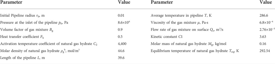
TABLE 1. Data of the parameters for model verification.
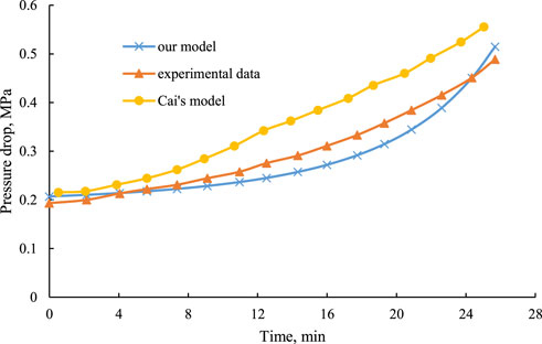
FIGURE 2. Results of our model, Cai’s model and the experimental data.
Model application
The model was used to predict the pressure along the real deep-water pipeline of China at the presence of natural gas hydrate. The data of the parameters in the model come from the real pipeline systems (Liang et al., 2009; Cai, 2018; Ding et al., 2019), which are exhibited in Table 2.
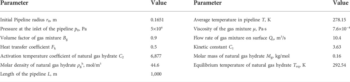
TABLE 2. Data of the parameters for model application.
Influence of natural gas hydrate on pipeline pressure
Pressure along the pipeline during 5 years of natural gas transport was calculated using our model. Results are shown in Figure 3.
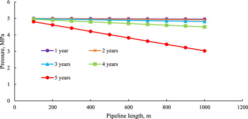
FIGURE 3. Pressure along the pipeline during 5 years of natural gas transport.
Figure 3 illustrates that the pressure decreases almost linearly along the pipeline. The decline of pressure is mainly caused by two aspects: laminar flow resistance in viscous flow and the reduction of pipeline radius due to the formation of natural gas hydrate. In order to compare the effects of these two aspects, we calculated the pressure along the pipelines with changeable radius and constant radius at the fifth year of natural gas transport in Figure 4. In the pipeline with changeable radius, fluid flow encounters the resistances caused by both laminar flow resistance and the reduction of pipeline radius. While in the pipeline with constant radius, fluid flow only encounters the laminar flow resistance. Results show that the reduction of pipeline radius plays a dominant role in the pressure drop inside the pipeline, because the pressure drop in the pipeline with changeable radius (1.97 MPa) is much more significant than the pipeline with constant radius (0.02 MPa). It also implies that taking into account the formation of natural gas hydrate is important to predict the pressure in the pipeline which transports natural gas in deep sea.
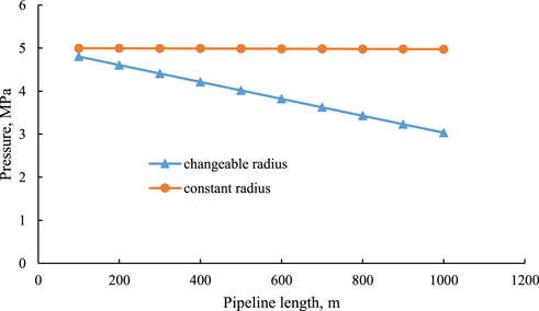
FIGURE 4. Pressure along the pipelines with changeable radius and constant radius at the fifth year of natural gas transport.
Characteristics of pipeline pressure decline
The decline of pressure during the first 3 years is much slower than the fifth year based on Figure 3. In order to investigate the pressure drop against time, we plot the pressure at 200, 400, 600, 800, and 1000 m of the pipeline during 5 years of natural gas transportation in Figure 5. In the first 3 years, the maximum pressure drop is only 0.19 MPa, accounting for a 3.8% of pressure loss, which occurs at the 1000 m of the pipeline. However at the fifth year, the pressure declines drastically to around 3 MPa at 1000 m with the 1.97 MPa of pressure drop. Nearly 40% of the pressure is reduced.
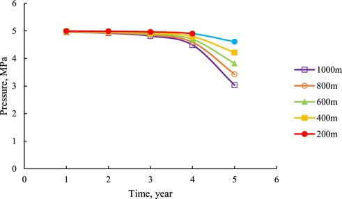
FIGURE 5. Pressure at 200, 400, 600, 800, and 1000 m of pipeline against time.
The drastic pressure drop is caused by the reduction of pipeline radius due to the formation of natural gas hydrate. The average reduction of pipeline radius during 5 years is shown in Figure 6. After 5 years of natural gas transport, 66.63% of pipeline radius is occupied by natural gas hydrate. This means that the formation and deposition of natural gas hydrate significantly affect the natural gas transport by blocking the pipeline. The growth of natural gas hydrate becomes faster as time goes by. And the blockage of pipeline tends to be more serious if the transportation continues without any treatments. As a result, the natural gas hydrate inside the pipeline should be cleared in time to maintain the good transport efficiency.
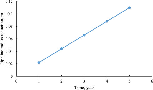
FIGURE 6. Average pipeline radius reduction during 5 years of natural gas transport.
Conclusion
1. The model considers changeable pipeline radius induced by the formation of natural gas hydrate. Therefore it provides a convenient and reliable way to predict the pipeline pressure, which is validated by the experimental data.
2. The decline of pressure inside the pipeline is mainly due to the reduction of pipeline radius caused by natural gas hydrate compared with the flow resistance induced by viscous flow.
3. The growth of natural gas hydrate becomes faster against time, and the blockage of pipeline tends to be more serious. This leads to the decline of pressure along the pipeline with a nearly 40% of pressure loss at the fifth year.
Data availability statement
The original contributions presented in the study are included in the article/supplementary material, further inquiries can be directed to the corresponding authors.
Author contributions
FM: Model establishment; Model verification; Methodology; Data analysis; Original draft preparation; Funding receiver. ZQ: Model application; Review and editing; Funding receiver. XH: Review and editing; Funding receiver. WY: Model verification; Review and editing. SW: Review and editing. QL: Data analysis; Preparation of the revised manuscript.
Funding
This work was financially supported by the Science and Technology Research Project of Chongqing Municipal Education Commission (Grant No. KJQN202001512), the Chongqing Research Program of Basic Research and Frontier Technology (Grant Nos cstc2019jcyj-zdxmX0032 and cstc2018jcyjAX0700), and the Research Foundation of Chongqing University of Science and Technology (Grant No. ckrc2019023).
Conflict of interest
Author QL was employed by the company China National Offshore Oil Corporation Research Institute Co., Ltd.
The remaining authors declare that the research was conducted in the absence of any commercial or financial relationships that could be construed as a potential conflict of interest.
Publisher’s note
All claims expressed in this article are solely those of the authors and do not necessarily represent those of their affiliated organizations, or those of the publisher, the editors and the reviewers. Any product that may be evaluated in this article, or claim that may be made by its manufacturer, is not guaranteed or endorsed by the publisher.
References
Boxall, J., Davies, S., Koh, C., and Sloan, E. D. (2009). Predicting when and where hydrate plugs form in oil-dominated flowlines. SPE Proj. Facil. Constr. 4 (3), 80–86. doi:10.2118/129538-pa
Boxall, J. (2009). Hydrate plug formation from <50% water content water-in-oil emulsions (Golden, Colorado, U.S.: Colorado School of Mine). Dissertation for Doctoral Degree.
Cai, T. (2018). Model for predicting deposition and collapse of natural gas hydrate in pipeline. Drill. Prod. Technol. 41 (6), 46–50. doi:10.3969/JISSN1006-768X.2018.06.14
Creek, J., Subramanian, S., and Estanga, D. (2011). “Project design hydrate management by application of multiphase flow simulations tools with hydrate formation and transport,” in Proceedings of the 7th International Conference on Gas Hydrates, Edinburgh, UK, 17-21 July 2011.
Davies, S. R., Boxall, J. A., Dieker, L. E., Sum, A. K., Koh, C. A., Sloan, E. D., et al. (2010). Predicting hydrate plug formation in oil-dominated flowlines. J. Pet. Sci. Eng. 72, 302–309. doi:10.1016/j.petrol.2010.03.031
Davies, S. R. (2009). The role of transport resistances in the formation and remediation of hydrate plugs (Golden: Colorado School of Mine). Dissertation for Doctoral Degree.
Ding, J., Liu, J., and Liang, D. (2019). OLGA based simulation on the formation laws of hydrates in pipelines. Oil Gas Storage Transp. 38 (2), 235–240. doi:10.6047/j.issn.1000-8241.2019.02.018
Gao, J. (2018). Prediction and prevention of hydrate in LW submarine pipeline (Chengdu, China: Southwest Petroleum University). Dissertation for Master’s Degree.
Ke, W., Zhang, J., Deng, L., Xu, Z., Zhao, D., and Jiang, X. (2021). Application of feedforward neural network in predicting subsea pipeline pressure under slug flow. Pet. Eng. Constr. 47 (6), 7–10. doi:10.3969/j.issn.1001-2206.2021.06.002
Li, C., Huang, T., and Jia, W. (2016). A review of natural gas hydrates and its pipeline transportation technologies in deep water. Chin. Sci. Bull. 61 (22), 2449–2462. doi:10.1360/n972015-01344
Li, W., and Dong, J. (2019). Experimental device and testing technology for hydrate in multiphase flow in large-scale submarine pipeline. Chem. Eng. Equip. 10, 123–125. doi:10.19566/j.cnki.cn35-1285/tq.2019.10.046
Li, W., Gong, J., Lu, X., Zhao, J., Feng, Y., and Yu, D. (2013). A study of hydrate plug formation in a subsea natural gas pipeline using a novel high-pressure flow loop. Pet. Sci. 10, 97–105. doi:10.1007/s12182-013-0255-8
Liang, F., Cao, X., Wei, J., and Chen, J. (2009). Application of accumulated liquid volume prediction method in submarine gas pipeline. Nat. Gas. Ind. 29 (1), 103–105. doi:10.3787/j.issn.1000.0976.2009.01.029
Lorenzo, M. D., Aman, Z. M., Soto, G. S., Johns, M., and May, E. F. (2014). Hydrate formation in gas-dominant systems using a single-pass flowloop. Energy fuels. 28 (5), 3043–3052. doi:10.1021/ef500361r
Mo, F., Qi, Z., Huang, X., Yan, W., Wang, S., Yuan, Y., et al. (2022). Knudsen diffusion in pore-scale water-bearing shales: Modelling and case study. J. Pet. Sci. Eng. 214, 110457. doi:10.1016/j.petrol.2022.110457
Mo, F., Qi, Z., Yan, W., Huang, X., and Li, J. (2020). Influence of water on gas transport in shale nanopores: Pore-scale simulation study. Energy fuels. 34 (7), 8239–8249. doi:10.1021/acs.energyfuels.0c01278
Ren, J. (2018). Numerical Simulation of Natural Gas Leakage in Deep-sea Pipeline Based on Pressure Gradient Change and Hydrate Formation, Dissolution and Decomposition Mechanisms (Tianjin, China: Tianjin University). Dissertation for Master’s Degree.
Shi, B. H., Jing, G., Sun, C. Y., Zhao, J. K., Ding, Y., and Chen, G. J. (2011). An inward and outward natural gas hydrates growth shell model considering intrinsic kinetics, mass and heat transfer. Chem. Eng. J. 171 (3), 1308–1316. doi:10.1016/j.cej.2011.05.029
Sonne, J., and Pedersen, K. (2009). “Simulation of hydrate growth in steady state flow lines,” in Proceedings of the BHR 14th International Conference on Multiphase Production Technology, Cannes, France, June 17–19, 2009, 2009, 17–19.
Wang, C., Peng, X., Liu, J., Jiang, R., Li, X. P., Liu, Y. S., et al. (2022). A novel formulation representation of the equilibrium constant for water gas shift reaction. Int. J. Hydrogen Energy, 2022. doi:10.1016/j.ijhydene.2022.06.105
Wang, C., Wang, J., Liu, Y., Li, J., Peng, X. L., Jia, C. S., et al. (2021). Prediction of the ideal-gas thermodynamic properties for water. J. Mol. Liq. 321 (2021), 114912. doi:10.1016/j.molliq.2020.114912
Wang, H., Lian, Z., and Wang, S. (2021). The hydrate formation and its influencing factors in submarine pipeline by using OLGA. Ocean Dev. Manag. 2, 87–92. 1005-9857(2021)02-0087-06
Xu, J., Chen, Z., and Li, R. (2020). Impacts of pore size distribution on gas injection in intraformational water zones in oil sands reservoirs. Oil Gas. Sci. Technol. –. Rev. IFP. Energies Nouv. 75, 75. doi:10.2516/ogst/2020047
Xu, J., Wu, K., Li, R., Li, Z., Li, J., Xu, Q., et al. (2018). Real gas transport in shale matrix with fractal structures. Fuel 219, 353–363. doi:10.1016/j.fuel.2018.01.114
Xu, J., Wu, K., Li, R., Li, Z., Li, J., Xu, Q., et al. (2019). Nanoscale pore size distribution effects on gas production from fractal shale rocks. Fractals 27 (08), 1950142. doi:10.1142/s0218348x19501421
Zerpa, L. E., Sloan, E. D., Sum, A. K., and Koh, C. A. (2012). Overview of CSMHyK: A transient hydrate formation model. J. Pet. Sci. Eng. 98-99, 122–129. doi:10.1016/j.petrol.2012.08.017
Keywords: natural gas hydrate, pressure, blockage, pipeline, deep water
Citation: Mo F, Qi Z, Huang X, Li Q, Yan W and Wang S (2022) Pressure prediction in deep-water pipeline considering formation of natural gas hydrate. Front. Earth Sci. 10:987594. doi: 10.3389/feart.2022.987594
Received: 06 July 2022; Accepted: 18 July 2022;
Published: 16 August 2022.
Edited by:
Jinze Xu, University of Calgary, CanadaReviewed by:
Chaowen Wang, Southwest Petroleum University, ChinaLan Wang, China University of Geosciences, China
Copyright © 2022 Mo, Qi, Huang, Li, Yan and Wang. This is an open-access article distributed under the terms of the Creative Commons Attribution License (CC BY). The use, distribution or reproduction in other forums is permitted, provided the original author(s) and the copyright owner(s) are credited and that the original publication in this journal is cited, in accordance with accepted academic practice. No use, distribution or reproduction is permitted which does not comply with these terms.
*Correspondence: Fei Mo, bW9mZWlfY3F1c3RAMTYzLmNvbQ==; Zhilin Qi, cWl6aGlsaW43NkBzaW5hLmNvbQ==; Xiaoliang Huang, MjAwOTAyMkBjcXVzdC5lZHUuY24=