- 1Key Laboratory of Geological Hazards on Three Gorges Reservoir Area, Ministry of Education, China Three Gorges University, Yichang, China
- 2College of Traffic and Transportation, Chongqing Jiaotong University, Chongqing, China
Worldwide, it is a great challenge to tunnel in portal section, where excessive deformation, cracking, or even collapse often occurs during the construction process. This paper presents a comparison study of face stability between entering and exiting a shallow-buried tunnel with a front slope. Firstly, the theoretical solutions of support pressure σT and safety coefficient FS of the excavation face considering surface slope are derived by upper-bound limit analysis method. Secondly, for different slope angles, buried depth and surrounding rocks of the exit and entrance sections, the σT and FS are obtained. The results show that when the burial depth of the tunnel crown h remain constant, the σT increased first and then decreased while the FS increased gradually, and both become steady when the slope angle α arrive at a certain value. In addition, the thicker the h is, the smaller the certain value α is. When the h and α remain constant, the loose area in front of the excavate face will decreased apparently with the increase of the internal friction angle φ, thus the σT will decrease and FS will increase. Moreover, the σT decreased linearly with the increase of cohesion c and unit weigh γ of surrounding rock, while the FS is the opposite. Compared with the entrance section, the construction risk at the exit section is greater.
1 Introduction
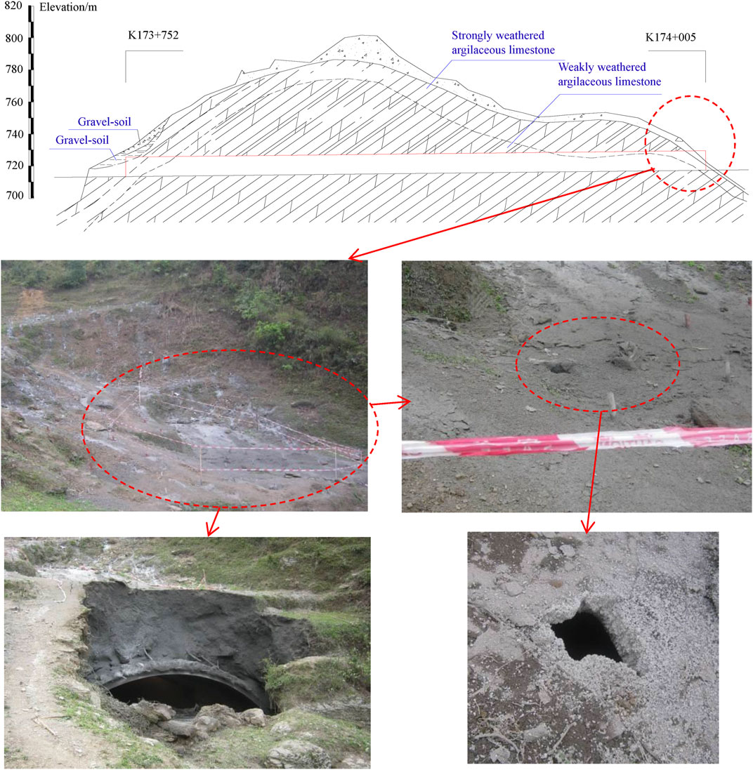
The tunnel portal section is often affected by unfavorable terrain and geological conditions such as shallow burial depth, unsymmetrical loading and broken surrounding rocks, resulting in various damages such as excessive deformation, cracking, or even collapse during the construction process (Ye et al., 2012; Liu et al., 2015). Currently, there have been a large number of studies and reports on tunnel portal section, covering various aspects such as pre-reinforcement technology (Coulter and Martin, 2006; Xiao et al., 2016; Yang et al., 2019), slope and face stability (Adam et al., 2014; Lei et al., 2015; Yuan et al., 2020; Zhou et al., 2021; Li et al., 2022), excavation methods and support (Miura, 2003; Yang et al., 2021), damage and treatment (Kontogianni et al., 2004; Yang et al., 2019; Cui et al., 2021), and others (He and Kusiak, 2017; Li et al., 2021a; Li et al., 2021b). However, the existing literatures has mainly focus on the condition of entering the tunnel, while relatively few studies have been carried out on the exit section. Actually, the occurrence of all kinds of damage in the tunnel exit section is not uncommon, such as the Pingzhai Tunnel of Xiamen—Chengdu Highway, due to shallow burial and low quality of surrounding rock, collapse occurred during exiting process. Firstly, a circular collapse about 50 cm appeared on the surface (Figure 1), and the collapse gradually increased with the further excavation. The distortion of primary support, breakage of pipe roof and collapse of slope in the tunnel exit section of Wafanggou Tunnel of Shangzhou - Manchuanguan Highway (Li, 2009). Li and Yang (2016) used a 3D numerical model to simulate the excavation of Pingzhai Tunnel portal, the result showed that the stress and deformation of surrounding rock are different between entering and exiting the portal using the same excavation method.
Limit analysis method or limit equilibrium method is often used in the theoretical analysis of tunnel excavation face stability. In 1987, Broms and Bennermark, (1967) firstly put forward the concept of stability factor N of tunnel face in undrained clay stratum and suggested that n < 6 should be taken as the condition for the excavation face to remain stable. In the following decades, this method has been widely used and improved. For instance, Anagnostou and Perazzelli (2013) and Wu et al. (2015) proposed formulas for calculating the limit support pressure considering the arching effect in soil, respectively. Liang et al. (2017) changed the failure area of the square wedge body in front of excavation face into the spiral body, and deduced the calculation model considering excavation footage. Leca and Dormieux (1990) proposed a failure criterion for the tunnel face in the general case of a cohesive and friction soil, and provided charts to allow a bracketed estimate of the required retaining pressure. Based on the Leca’s model, Mollon et al. (2009) and Zhang et al. (2015) proposed the failure modes composing of multiple rigid truncated cones, and obtained the upper-bound solution for the face stability through optimization, respectively. Zhao et al. (2017) obtained the optimal upper limit solution for support pressure by using the sequential quadratic programming method. The above mentioned literatures are mainly carried out under the condition that the surface is horizontal. However, the tunnel portal section is usually shallow buried, hence the effect of surface slope should not be ignored.
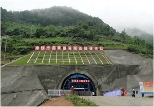
In this paper, the tunnel portal with a front slope, which is one of the most typical portal types, is taken to investigate the difference between entering and exiting the tunnel. As shown in Figure 2, the covering depth of this tunnel on the left and right sides is almost the same, and therefore no obviously unsymmetrical loading is formed. However, the covering depth gradually increases along the tunnel axis to form a front slope with a dip direction parallel to the tunnel axis. The construction of this tunnel portal section, i.e., excavation at the foot of the front slope, will easily lead to the instability of slope and surrounding rock. Firstly, the theoretical solutions of support pressure σT and safety coefficient FS of the excavation face considering surface slope are derived by upper-bound limit analysis method. Then the face stability under entering and exiting conditions is systematically compared through calculation the σT and FS of different burial depth, surrounding rock parameters and the slope angles. The conclusion can serve as references for the excavation and support of similar engineering.
2 Limit analysis of the tunnel face stability
2.1 Failure mode
Since such tunnel portal is symmetrically distributed along the center line, a two-dimensional model can be used for simplified analysis. The assumed failure mode of tunnel face is shown in Figure 3, AB is the excavation face; BF is the sliding surface on the top of the vault; AF is the sliding surface on the lower part of the bottom vault. According to the research results of Chambon and Corté (1994) and Takano et al. (2010), it is assumed that the loose area in front of the face is in the shape of a logarithmic spiral, i.e. AF in Figure 3 is a logarithmic spiral curve (O is the center point), and the equation is
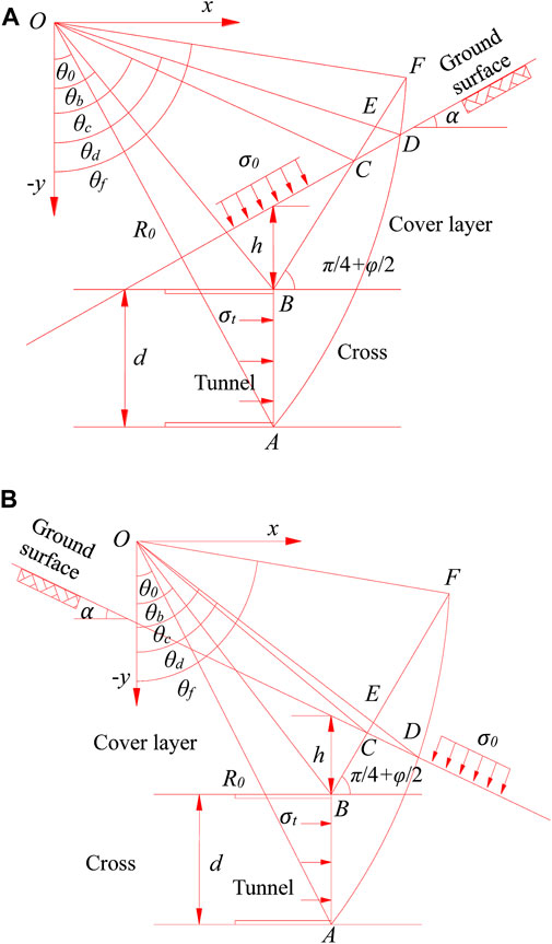
FIGURE 3. The failure model of tunnel face at portal section: (A) entrance section; (B) exit section.
The included angle between AF and the horizontal plane at the tunnel bottom surface, the included angle between BF and the horizontal plane, and the included angle between OA and the–y axial are all (π/4+φ/2) (Chambon and Corté, 1994; Takano et al., 2010).
2.2. Geometry parameter
As shown in Figure 3, the equations for BF and the ground surface CD are
The coordinates of points A (xA and yA), B (xB and yB), C (xC and yC), D (xD and yD) and F (xF and yF) can be easily obtained by combining the above (Eqs. 1–3), and the values are as follows respectively:
From Eqs 4–8, the length ROD, ROF, LOB, LOC, LBC, LCD and LBF can be obtained.
2.3 External load power
When the rigid slider ABCD rotates around the center of rotation O (i.e., the origin of coordinates), the sliding surfaces AD and BC are velocity discontinuity surfaces. The power of the external work done by ABCD due to its own weight can be obtained by adding the power algebraic of the external work done by the blocks OAB, OBC, OCD, and OAD. The specific expression of the power done by each block due to its own weight is as follows:
As shown in Figure 3A, for the entrance section, the power of the external work done by ABCD due to its own weight is
and Eq. 13 is also applicable for the exit section when (π/2+α) > θc (as shown in Figure 3B, the corresponding α of the exit is a negative value). For the exit section when (π/2+α)<θc, the power of external work done by ABCD due to its own weight is
When the intersection F between AF and BF is located inside the slope, the power of the external work done by the rigid slider ABF due to its own weight can be obtained by algebraically adding the external work power done by OAB, OAF, and OBF
When the slider ABF is located inside the slope, the power of external work done due to its own weight is as follows:
The power W0 and WT of the external work done by the surface overload σ0 and the supporting pressure σT on the tunnel excavation surface is as follows respectively:
2.4 Internal energy dissipation
According to the upper-bound theorem of limit analysis, the internal energy dissipation on the section between different speeds is calculated. The energy dissipation of the failure mode shown in Figure 3 includes the energy consumption on AD and BC on the top of the vault. The calculation formula is as follows:
Then, the total internal energy dissipation on the sliding surface is
When the intersection F between AF and BF is located inside the slope, the total internal energy dissipation on the sliding surface is
2.5 Calculation and verification
According to the virtual work principle in the limit analysis theory, the external load power is equal to the internal energy dissipation power, i.e. D = WG+W0+WT, and the objective function of the limit support pressure σT of the tunnel excavation face is obtained as follows:
The strength reduction method was adopted to obtain the safety coefficient FS of the tunnel face
where c and φ are the cohesion and friction angle of the surrounding rocks, respectively. And c’ and φ′ are the reduction parameters of the cohesion and friction angle for the failure of the excavation face, respectively. Substituting Eq. 25 into Eq. 24 so as to make sure σT of the tunnel face is equal to 0, and then FS of the tunnel face can be obtained.
Calculations of σT at given parameter values (c = 7 kPa, φ=17°, γ =18 kN/m3, D=10 m, σ0 =0 kPa) are carried out and comparisons with others are conducted. Graphically, the calculation results are depicted in Figure 4. It can be seen that the calculation results in this paper are very close to those in the existing literatures, which are 6.2 and 6.5% lower than those of Mollon et al. (2009) and Zhao et al. (2017), respectively, but are 11.9% higher than those of Leca and Dormieux. (1990). When c/d is greater than 0.6, the loose area is located inside the slope, and σT of the face is constant, which is consistent with the actual situation. Through the above comparison and analysis, the rationality and correctness of the calculation method in this paper are verified.
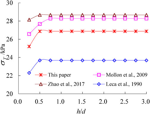
FIGURE 4. Calculated limit support pressure σT at given parameters (c = 7 kPa, φ=17°, γ =18 kN/m3, D=10 m, σ0 =0 kPa).
3 Comparison in entering and exiting
The slope at the tunnel entrance and exit sections is indicated by α (a positive value representing the slope of the ground surface at the tunnel entrance section or a negative value representing the slope of the ground surface at the tunnel exit section). In order to analyze the influence of the surface slope at the tunnel entrance and exit sections on the stability of the tunnel surface, the following parameters are taken: D =10 m, h =4 m, γ =18 kN/m3, c =7 kPa and φ=17°. When analyzing the influence of a certain factor on the stability of the tunnel face, other parameters shall remain unchanged.
3.1 Different burial depth
The relationships between the σT and FS of the tunnel face and the slope of the ground under the condition of different burial depth of the tunnel crown h are shown in Figure 5.
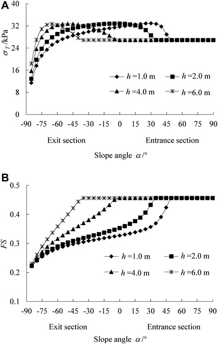
FIGURE 5. Limit support pressure σT and safety coefficient FS changing with slope angle α and burial depth h (A) σT; (B) FS.
Figure 5A shows under the same h, with the increase of α, the σT of the face increases first, and then decreases to a certain value, and eventually goes steady. When the σT is constant, the loose area in front of the face will be all inside the slope, and the loose area no longer extends upward due to the arching effect of the surrounding rock, so the increase of h will not lead to the increase of σT. When the α is small, the loose area will shrink, thus the required σT will decrease; With the increase of α and the loose area, the increase of external load power will decrease gradually, while the increase of internal energy dissipation on the sliding surface is approximately a constant value (Figure 3), thus causing σT increasing first and then decreasing. In addition, it is easy to understand that the larger the h is, the smaller the corresponding α when reaching the maximum value and the constant value, and the change of h has no influence on the maximum value and the constant value of σT.
Figure 5B shows when h is the same, the FS of the face increases gradually with the increase of the surface slope until the loose area is completely inside the slope; when the α remains a small value, the larger the h is, the larger the corresponding FS is. When α = −70° and H = 1.0 m, the corresponding FS and σT are the smallest; when α = −15° and H = 1.0 m, the corresponding FS is the largest, but the σT is the largest.
According to the above results, the stability of the tunnel face at the exit section is lower than that at the entrance section. When the loose area is completely located inside slope, the stability of the excavation face are the highest.
3.2 Strength parameters of different surrounding rocks
3.2.1 Internal friction angle φ
When the internal friction angle φ of the surrounding rock is different, the relationship between the σT and FS of the tunnel face and the surface slope α is shown in Figure 6.
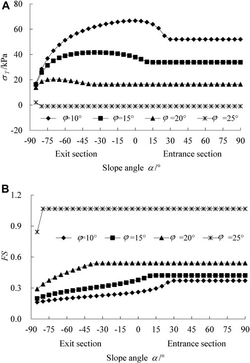
FIGURE 6. Limit support pressure σT and safety coefficient FS changing with slope angle α and internal friction angle φ: (A) σT; (B) FS.
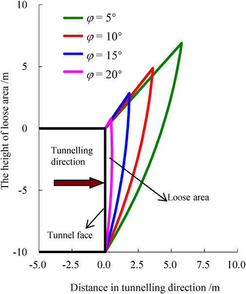
It can be seen that when h is constant and φ is small, the σT of the face increases with the increase of α and then decreases, and finally tends to be constant; FS of the face gradually increases with the increase of α, and finally reaches a constant value; the larger the φ is, the smaller the α is when σT and FS reach constant values. When the α is large, σT and FS of the face are both constant; when α is constant, the larger the φ is, the smaller the corresponding σT is, and the larger the FS is. The main reason is that the increase of φ makes the loose area in front of the face decrease significantly, resulting in a significant reduction of external load power, as shown in Figure 7. And when the σT and FS are constant, it means that the loose area of the surrounding rock is completely located inside the slope, and the loose area is no longer developed upward due to the arching effect of the surrounding rock.
3.2.2 Cohesion c
Under different cohesion c, the relationship between the σT and FS of the tunnel face and the surface slope α is shown in Figure 8. When α is constant, the σT decrease linearly with the increase of c, while FS increase linearly with the increase of c.
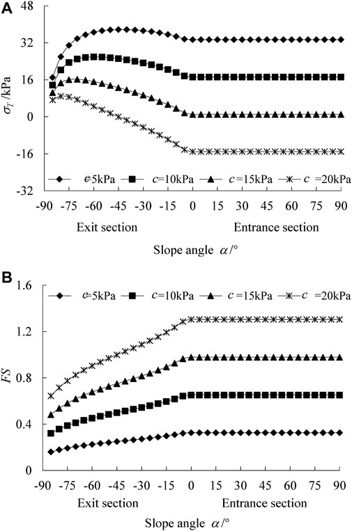
FIGURE 8. Limit support pressure σT and safety coefficient FS changing with slope angle and soli cohesion: (A) σT; (B) FS.
When the surface is horizontal (i.e., α = 0°), the change law of c and φ corresponding to different FS are shown in Figure 9. The values of other parameters are as follows: d =10 m, h = 10 m, and γ = 20 kN/m3. It can be seen that c and φ can significantly affect the FS. When the FS of the face is constant, the required c decreases gradually with the increase of the φ, and the decreasing amplitude increases gradually. The larger the φ is, the smaller the difference in c required to meet the requirements of different stability factors of the excavation face is.
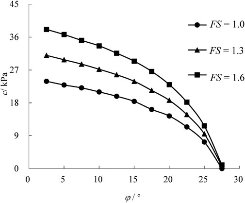
FIGURE 9. Change law of cohesion c and internal friction angle φ of the surrounding rock corresponding to different safety coefficients FS (α =10°, d =10 m, h = 10 m, and γ = 20 kN/m3).
3.3 Unit weight of the surrounding rock γ
Under the condition of different unit weight γ of surrounding rocks, the relationship between σT and FS of the tunnel face and α is shown in Figure 10. It can be seen that when the α is the same, the σT and FS of the tunnel face decrease and increase linearly with the increase of γ, respectively.
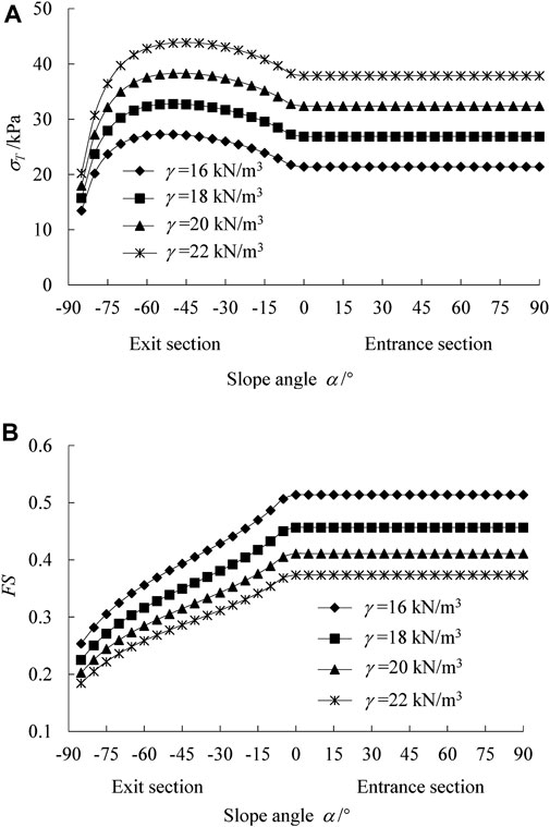
FIGURE 10. Limit support pressure σT and safety coefficient FS changing with slope angle and unit weight of surrounding rock: (A) σT; (B) FS.
4 Conclusions and perspectives
Based on the upper-bound theorem of limit analysis, a calculation method to quantitatively analyze the limit support pressure σT and safety coefficient FS of the tunnel face is put forward. Compared with the existing literature results, the correctness and effectiveness of this method adopted in this paper are verified. By using such method, the calculation of the σT and FS of the tunnel face under the conditions of different surface slopes α at the tunnel entrance and exit sections is carried out. The following conclusions are drawn:
1) The σT of the tunnel face increases first and then decreases with the increase of α and finally reaches a constant value; the FS increases gradually with the increase of α, and goes steady when α increases to a certain value.
2) When α is small, the FS of the tunnel face gradually increases with the increase of the burial depth of the tunnel crown h; when the loose area in front of the excavation is completely located inside the slope, the loose area no longer develops upward due to the arching effect, so when the slope increases by a certain amount, the σT and FS of the tunnel face are no longer affected by the change of h.
3) The cohesion c and internal friction angle φ of the surrounding rock can significantly affect the σT and FS of the face. The increase of φ will obviously reduce the loose area in front of the face and will significantly improve the face stability; when the α is constant, the σT and FS of the face increase linearly with the increase of c and unit weight of the surrounding rock γ. The larger the φ is, the smaller the difference in c required to meet the requirements of different safety coefficients of the excavation face is.
4) For shallow buried tunnel, the FS of exiting is relatively low compared with that of entering. Therefore, more attention should be paid during the excavation of exiting the tunnel.
5) Research results show that the face stability between entering and exiting excavation is different for the shallow-buried tunnel with a front slope, which can serve as references for the excavation and support of this portal. Further research can be carried out for other types of tunnel portals, such as the shallowly buried and asymmetrically loaded tunnel portal.
Data availability statement
The raw data supporting the conclusions of this article will be made available by the authors, without undue reservation.
Author contributions
XZL: resources, data curation, project; investigation. XLL Calculation: Theoretical methods; validation. CY: writing-original draft preparation; editing; project.
Funding
This work is supported by the National Natural Science Foundation of China (No. 42177132); Natural Science Foundation of Hubei Province (Nos. 2021CFA090 and 2021CFB536); the Open Fund of Key Laboratory of Geological Hazards on Three Gorges Reservoir Area (China Three Gorges University), Ministry of Education (2015KDZ04).
Conflict of interest
The authors declare that the research was conducted in the absence of any commercial or financial relationships that could be construed as a potential conflict of interest.
Publisher’s note
All claims expressed in this article are solely those of the authors and do not necessarily represent those of their affiliated organizations, or those of the publisher, the editors and the reviewers. Any product that may be evaluated in this article, or claim that may be made by its manufacturer, is not guaranteed or endorsed by the publisher.
Abbreviations
FS, safety coefficient; R, polar radius of the logarithmic spiral curve (m); R0, length of OA (m); ROD, length of OD (m); ROF, length of OF (m); LOB, length of OB (m); LOC, length of OC (m); LBC, length of BC (m); LCD, length of CD (m); LBF, length of BF (m); θ, polar angle of the logarithmic spiral curve (°); θ0, included angle between OA and –y axial (°); θb, included angle between OB and –y axial (°); θc, included angle between OC and –y axial (°); θd, included angle between OD and –y axial (°); θf, included angle between OF and –y axial (°); h, burial depth of the tunnel crown (m); d, tunnel height (m); α, included angle between ground surface and the horizontal plane (°), it is positive at the entrance and negative at the exit; γ, unit weight (kN/m3); c, cohesion (kPa); φ, internal friction angle (°); σT, support pressure distributed on the excavation surface (kPa); σ0, additional pressure acting on the surface (kPa); ω, rotational angular velocity.
References
Adam, D., Markiewicz, R., and Brunner, M. (2014). Block-in-matrix structure and creeping slope: Tunneling in hard soil and/or weak rock. Geotech. Geol. Eng. (Dordr). 32 (6), 1467–1476. doi:10.1007/s10706-012-9591-5
Anagnostou, G., and Perazzelli, P. (2013). The stability of a tunnel face with a free span and a non-uniform support. Geotechnik 36 (1), 40–50. doi:10.1002/gete.201200014
Broms, B. B., and Bennermark, H. (1967). Stability of clay at vertical opening. J. Soil Mech. Found. Div. 93 (1), 71–94. doi:10.1061/jsfeaq.0000946
Chambon, P., and Corté, J. F. (1994). Shallow tunnels in cohesionless soil: Stability of tunnel face. J. Geotech. Engrg. 120 (7), 1148–1165. doi:10.1061/(asce)0733-9410(1994)120:7(1148)
Coulter, S., and Martin, C. D. (2006). Effect of jet-grouting on surface settlements above the Aeschertunnel, Switzerland. Tunn. Undergr. Space Technol. 21 (5), 542–553. doi:10.1016/j.tust.2005.07.005
Cui, S., Pei, X., Jiang, Y., Wang, G., Fan, X., Yang, Q., et al. (2021). Liquefaction within a bedding fault: Understanding the initiation and movement of the Daguangbao landslide triggered by the 2008 Wenchuan Earthquake (Ms = 8.0). Eng. Geol. 295, 106455. doi:10.1016/j.enggeo.2021.106455
He, Y., and Kusiak, A. (2017). Performance assessment of wind turbines: Data-derived quantitative metrics. IEEE Trans. Sustain. Energy 9 (1), 65–73. doi:10.1109/tste.2017.2715061
Kontogianni, V., Tzortzis, A., and Stiros, S. (2004). Deformation and failure of the tymfristos tunnel, Greece. J. Geotech. Geoenviron. Eng. 130, 1004–1013. doi:10.1061/(asce)1090-0241(2004)130:10(1004)
Leca, E., and Dormieux, L. (1990). Upper and lower bound solutions for the face stability of shallow circular tunnels in frictional material. Geotechnique 40 (4), 581–606. doi:10.1680/geot.1990.40.4.581
Lei, M. F., Peng, L. M., and Shi, C. H. (2015). Model test to investigate the failure mechanisms and lining stress characteristics of shallow buried tunnels under unsymmetrical loading. Tunn. Undergr. Space Technol. 46, 64–75. doi:10.1016/j.tust.2014.11.003
Li, H., Deng, J., Feng, P., Pu, C., Arachchige, D., and Cheng, Q. (2021a). Short-term nacelle orientation forecasting using bilinear transformation and ICEEMDAN framework. Front. Energy Res. 9, 780928. doi:10.3389/fenrg.2021.780928
Li, H., Deng, J., Yuan, S., Feng, P., and Arachchige, D. (2021b). Monitoring and identifying wind turbine generator bearing faults using deep belief network and EWMA control charts. Front. Energy Res. 9, 799039. doi:10.3389/fenrg.2021.799039
Li, H., He, Y., Xu, Q., Deng, j., Li, W., and Wei, Y. (2022). Detection and segmentation of loess landslides via satellite images: A two-phase framework. Landslides 19, 673–686. doi:10.1007/s10346-021-01789-0
Li, J. M., and Yang, C. (2016). Impact of excavation sequence from inside on surrounding rock stability at the portal of a shallow and unsymmetrically loaded tunnel. Electron. J. Geotechnical Eng. 21 (13), 4739–4749.
Li, T. J. (2009). Cause analysis of tunnel initial support deformation and the treatment. Highw. Auto Appl. 4 (3), 197–199. (in Chinese). doi:10.3969/j.issn.1671-2668.2009.03.063
Liang, Q., Yang, X. L., and Chen, X. (2017). Limit equilibrium analysis of round length in tunnel excavation. J. South China Univ. Technol. Nat. Sci. Ed. 45 (5), 123–119. (in Chinese). doi:10.3969/j.issn.1000-565X.2017.05.016
Liu, X. J., Yang, C., and Yu, J. (2015). The influence of moisture content on the time-dependent characteristics of rock material and its application to the construction of a tunnel portal. Adv. Mater. Sci. Eng. 2015, 1–13. doi:10.1155/2015/725162
Miura, K. (2003). Design and construction of mountain tunnels in Japan. Tunn. Undergr. Space Technol. 18, 115–126. doi:10.1016/s0886-7798(03)00038-5
Mollon, G., Dias, D., and Soubra, A. H. (2009). Probabilistic analysis and design of circular tunnels against face stability. Int. J. Geomech. 9 (6), 237–249. doi:10.1061/(asce)1532-3641(2009)9:6(237)
Takano, D., Otani, J., Fukushige, S., and Natagani, H. (2010). Investigation of interaction behavior between soil and face bolts using X-ray CT. Adv. X-ray Tomogr. Geomaterials 26 (4), 389–395. doi:10.1002/9780470612187.ch41
Wu, J., Liao, S. M., and Shi, Z. H. (2015). Workface stability of shield tunnel considering arching effect. J. Tongji Univ. Nat. Sci. 43 (2), 213–220. (in Chinese). doi:10.11908/j.issn.0253-374x.2015.02.008
Xiao, J. Z., Dai, F. C., Wei, Y. Q., Xing, Y. C., Cai, H., and Xu, C. (2016). Analysis of mechanical behavior in a pipe roof during excavation of a shallow bias tunnel in loose deposits. Environ. Earth Sci. 75 (4), 293. doi:10.1007/s12665-015-5176-y
Yang, C., Chen, Y. H., Guo, Z., and Wang, R. H. (2021). Surface settlement control in the excavation of a shallow intersection between a double-arched tunnel and a connection. Tunn. Int. J. Geomechanics 24 (4), 04021035. doi:10.1061/(ASCE)GM.1943-5622.0001983
Yang, C., Chen, Y. H., Huang, D., and Wang, L. H. (2019). Arching effect between the pipes of a pipe umbrella support system in a shallow-buried tunnel. KSCE J. Civ. Eng. 23 (12), 5215–5225. doi:10.1007/s12205-019-5197-2
Yang, C., Hu, Z. X., Huang, D., and Guo, F. (2019). Failure mechanism of primary support for a shallow and asymmetrically loaded tunnel portal and treatment measures. J. Perform. Constr. Facil. 34, 0001385. doi:10.1061/(ASCE)CF.1943-5509.0001385
Ye, F., He, C., Wang, S. M., and Zhang, J. L. (2012). Landscape design of mountain highway tunnel portals in China. Tunn. Undergr. Space Technol. 29, 52–68. doi:10.1016/j.tust.2012.01.001
Yuan, B. X., Sun, M., Xiong, L., Luo, Q. Z., Pradhan, S. P., and Li, H. Z. (2020). Investigation of 3D deformation of transparent soil around a laterally loaded pile based on a hydraulic gradient model test. J. Build. Eng. 28 (3), 101024. doi:10.1016/j.jobe.2019.101024
Zhang, C., Han, K., and Zhang, D. (2015). Face stability analysis of shallow circular tunnels in cohesive–frictional soils. Tunn. Undergr. Space Technol. 50, 345–357. doi:10.1016/j.tust.2015.08.007
Zhao, L., Li, D., Li, L., Feng, Y., Cheng, X., and Luo, W. (2017). Three-dimensional stability analysis of a longitudinally inclined shallow tunnel face. Comput. Geotechnics 87, 32–48. doi:10.1016/j.compgeo.2017.01.015
Keywords: shallow-buried tunnel, face stability, upper-bound limit analysis, tunnel entrance, tunnel exit
Citation: Li X, Li X and Yang C (2022) A comparison study of face stability between the entering and exiting a shallow-buried tunnel with a front slope. Front. Earth Sci. 10:987294. doi: 10.3389/feart.2022.987294
Received: 06 July 2022; Accepted: 25 July 2022;
Published: 31 August 2022.
Edited by:
Yusen He, Grinnell College, United StatesReviewed by:
Decheng Zhang, Hebei University of Technology, ChinaYamg Luo, Xi’an University of Architecture and Technology, China
Hao-sen Guo, East China Jiaotong University, China
Copyright © 2022 Li, Li and Yang. This is an open-access article distributed under the terms of the Creative Commons Attribution License (CC BY). The use, distribution or reproduction in other forums is permitted, provided the original author(s) and the copyright owner(s) are credited and that the original publication in this journal is cited, in accordance with accepted academic practice. No use, distribution or reproduction is permitted which does not comply with these terms.
*Correspondence: Xiulei Li, aGVsbG9saXhpdWxlaUAxNjMuY29t; Chao Yang, eWFuZ2NoYW8wNjE1QGN0Z3UuZWR1LmNu
 Xinzhe Li1
 Xiulei Li
 Chao Yang