- 1China Electric Power Research Institute Co., Ltd., Beijing, China
- 2Faculty of Engineering, China University of Geosciences, Wuhan, China
From a variety of yield stress fluid models, an elastoviscoplastic Herschel-Bulkley (EVPHB) model written in 3D is selected and coupled with a Finite Element Method with Lagrangian Integration Points (FEMLIP) to solve boundary value problems with large deformation process. By tracing the historical variables of a material point, it is verified that in a time-independent flow the elastic strain and viscous strain rate could be accurately reproduced by EVPHB model. For a time-dependent flow, because of the addition of elasticity, the EVPHB model makes the material experience a deformation process which is significantly distinctive from that produced by a pure regularized Herschel-Bulkley model. Benchmarks also show that in FEMLIP the yielded and unyielded zones could be easily defined by EVPHB model according to the stress of a material point. Lastly, it is shown that EVPHB model also induces a stress relaxation process for materials under constant strain. The suitability of FEMLIP to model elastoviscoplastic fluid is verified.
1 Introduction
Yield stress fluids are widely encountered in our surroundings, such as landslides, mud-debris flows and lava flows in mountain hazards; foams, emulsions, polymer pastes and chocolate in industries (Takeshi and Sekimoto, 2005; Ancey, 2007; Marmottant and Graner, 2007; Bénito et al., 2008; Balmforth et al., 2014). The fundamental feature of a yield stress fluid is that it behaves like a fluid once the yield stress is exceeded but deforms in a finite way like a solid if the material is not sufficiently stressed. In the history of constitutive models’ development for yield stress fluids, these materials were firstly treated as viscoplastic fluids, and thereafter, with the addition of elasticity, described by several types of elastoviscoplastic models.
1.1 Elastoviscoplasticity of yield stress fluid
Current popular viscoplastic models generally include Bingham (Bingham, 1922; Sousa and Voight, 1991; Whipple and Dunne, 1992), Herschel-Bulkley (Herschel and Bulkley, 1926; Laigle and Coussot, 1997) and bilinear rheological models (Locat, 1997). Bingham model (linear viscoplastic model) was the first model used to describe the viscoplastic behavior of yield stress fluids, in which the material behaves like a rigid solid and the magnitude of symmetric rate-of-strain tensor (
when
when
when
Because the original Bingham or Herschel-Bulkley models present a sharp discontinuity at the yield stress which is difficult to handle in numerical methods, Papanastasiou (Papanastasiou, 1987) proposed a regularization of Bingham model which eliminates the need for explicit yield-surface tracking (Papanastasiou model). Further developments of this approach were achieved by Mitsoulis et al. (Mitsoulw et al., 1993) and Papanastasiou and Boudouvis (Papanastasiou and Boudouvis, 1997), they proposed a regularized HB model by combining the original Herschel–Bulkley and Papanastasiou models, as shown in Eq. 4 in which the effective viscosity ηeff is a function of k, n, τ0,
Regularized Herschel-Bulkley model (RHB):
As an additional complexity, many yield stress fluids were proven to be elastoviscoplastic, with elastic deformations below the yield stress and a combination of recoverable (elastic) and unrecoverable (viscous) deformation above the yield stress (Yano and Daido, 1965; Luu and Forterre, 2009). The most widely used elastoviscoplastic model is the Perzyna model (Perzyna, 1962; Perzyna, 1966), and similar models were also proposed for different applications (Luu and Forterre, 2009; Cheddadi et al., 2012). The difference lies in the behavior of the viscous element, which is related to the second invariant of elastic strain tensor, follows either Bingham (linear) or Herschel-Bulkley (exponential) laws. A one-dimensional illustration of this class of models is shown in Figure 1A: before yielding the model behaves like an elastic solid (Eq. 5); and once stress is above yield stress, the model is a Maxwell fluid with a Bingham or Herschel-Bulkley viscosity (Eq. 6). In Eqs. 5, 6, μ is the elastic shear modulus; ε is the shear strain;
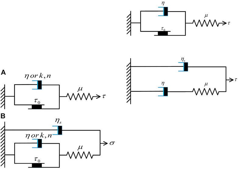
FIGURE 1. (A) Perzyna’s model or Cheddadi’s model or Luu and Forterre’s model, (B) Saramito’s elastoviscoplastic model.
when
when
1.2 Numerical simulation method
Yield stress fluids have been intensively modelled by conventional numerical methods, such as Finite Volume Method (FVM) (de Souza Mendes et al., 2007; Turan et al., 2012; Syrakos et al., 2013), Finite Difference Method (FDM) (Olshanskii, 2009; Muravleva et al., 2010) and Finite Element Method (FEM) (Adams et al., 1997; Blackery and Mitsoulis, 1997; Alexandrou et al., 2001; Saramito and Roquet, 2001). FVM and FDM are also categorized into Eulerian FEM, and are suitable for handling large deformations of history-independent materials without the problem of mesh distortion. However, these methods generally present severe numerical diffusion at the interfaces between different materials (Lenardic and Kaula, 1993; Van Keken et al., 1997), and render also difficult to track material-dependent properties. The conventional FEM, that is also categorized into Lagrangian FEM, is ideal for tracking history-dependent variables of a specified material point, such as stress, strain, displacement and so on. However, it presents severe mesh distortion for extremely large deformations.
To benefit from the capability of handling large deformation of Eulerian FEM and the tracking ability of historical properties of Lagrangian FEM, a lot of efforts were paid to develop new methods, such as Arbitrary Lagrangian-Eulerian method (Hirt et al., 1974; Donea et al., 1982), Material Point Method (Sulsky et al., 1994, 1995), Particle Finite Element Method-second generation (Idelsohn et al., 2013) and Finite Element Method with Lagrangian Integration Points (Moresi and Solomatov, 1995; Moresi et al., 2003). Arbitrary Lagrangian-Eulerian method (ALE) is the most classical method that attempts to capture the advantages of both the Lagrangian and the Eulerian methods in modelling large deformation problems by allowing the mesh in the interior of the domain to move independently of the material. However, this requires an additional remeshing algorithm and computational cost (Margolin, 1997; Knupp et al., 2002). Besides, ALE cannot handle properly very large deformation and history variable tracking in the same setting. The Material Point Method (MPM) (Sulsky et al., 1994, 1995) is an extension of the Particle-in-Cell (PIC) method (Harlow, 1964) which takes advantage of the combined Eulerian-Lagrangian approach. In MPM the material is represented as a collection of material points and their displacements are determined by Newton’s laws of motion, while the computational nodes are on a background mesh. MPM use linear shape functions which cause cell crossing noise in large deformation problems. Bardenhagen aned Kober (Bardenhagen and Kober, 2004) proposed to use higher-dimensional shape functions to improve the original MPM and developed the Generalized Interpolation Material Point Method (GIMP), which requires greater computational time. Particle Finite Element Method-second generation (PFEM-2) uses two approaches to communicate particle and mesh data. The first one is called Moving Mesh, which follows the original idea of PFEM (Idelsohn et al., 2004) creating a new mesh using the new position of the particles as nodes. This Moving Mesh approach leads to the evaluation of the mesh distortions and re-meshing processes which are always computationally expensive. The second version, named Fixed Mesh, projects the particle states to nodes while preserving the initial background mesh (Idelsohn et al., 2014), which avoids the remeshing at each time step.
In this paper we refer to a method that is quite similar to the PFEM-2 of Fixed Mesh version. It was firstly introduced by Moresi and Solomatov (Moresi and Solomatov, 1995) and named as Finite Element Method with Lagrangian Integration Points (FEMLIP). Similar to MPM or PFEM-2, FEMLIP is based on a kinematic dissociation between the Lagrangian material points and the computational nodes of the finite element Eulerian mesh. For a given material configuration, the material points are used as integration points on one element. The resolution of the equilibrium equations at the nodes gives a velocity field, and at the end of each step the velocity is interpolated from the nodes to the material points which are sequentially moved throughout the fixed mesh to a new configuration. This enables the use of standard, proven, structured grid solvers, and also enables the modelling of numerous, interacting materials, without the concern of numerical diffusion (Lenardic and Kaula, 1993; Van Keken et al., 1997). Historical variables of a material point or particle, such as strain, strain rate, or stress could be easily traced, which alleviates problems with the standard Eulerian formulation. The particularity of FEMLIP is its fast-implicit solution method and various particle-reweighting steps. At each time step, the particle weights are varied in order to obtain the correct integral for a given element and improve the accuracy in large fluid deformations (Moresi et al., 2003; Dufour and Pijaudier-Cabot, 2005). The Eulerian-Lagrangian dual traits of FEMLIP makes it well-suited for dealing with large transformations, and meanwhile tracking internal variables during material movement (Moresi et al., 2003; Dufour and Pijaudier-Cabot, 2005; Cuomo et al., 2013; Prime et al., 2014).
Due to their ability to deal both with small, solid-like, and large, fluid-like, deformations, coupled Eulerian-Lagrangian numerical methods appear attractive to model yield stress materials. Yet, the aforementioned state of art discloses that elastoviscoplastic models, which are currently the most advanced to represent the constitutive behavior of these materials, have rarely been implemented in such numerical approaches. In this paper, we investigate the interplay of elasticity, viscosity and plasticity in an elastoviscoplastic Herschel-Bulkley model (EVPHB for short) shown in Figure 1A in the framework of FEMLIP. Through several boundary value problems and demonstrative simulations, the implementation of EVPHB in FEMLIP will be verified by tracking the historical variables and the yielded and unyielded zones.
2 Implementation of herschel-bulkley and RHB models in finite element method with lagrangian integration points
2.1 Three dimensional constitutive model
For the simplicity of numerical implementation, Eqs. 5, 6 are unified into Eq. 7, where the total strain rate (
when
In addition, referring to, e.g., Oldroyd (Oldroyd, 1950) and Mitsoulis (Papanastasiou and Boudouvis, 1997), equations are generalized to three-dimensions by introducing the deviatoric stress tensor (
when
where
In order to compare this elastovisoplastic Herschel-Bulkley model (EVPHB) with a Herschel-Bulkley model without elasticity, we also introduce the three-dimensional tensorial form of the regularized Herschel-Bulkley model (RHB) introduced in Eq. 4 (Papanastasiou and Boudouvis, 1997):
2.2 Implementation in finite element method with lagrangian integration points
The Stokes equations solved in FEMLIP are shown in Eqs. 14, 15 in strong form, in which
Time discretization:
where
where
3 Analysis and validation of EVPHB model
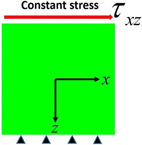
In order to investigate the traits of EVPHB model, as well as to see its difference from a Herschel-Bulkley model without elasticity (RHB), several numerical simulations were performed with FEMLIP. Figure 2 shows the sketch of the shear test of an infinite layer simulated in FEMLIP, in which a square of yield-stress material with a length of 0.03 m is fixed at the bottom while a constant deviatoric stress (
3.1 Simple shear test with constant applied stress
3.1.1 Shear stress boundary condition lower than yield stress
A constant shear stress (80 Pa) smaller than the yield stress of the material (91 Pa), is applied on the top boundary of shear layer (Figure 2). From Eq. 6, it is known that strain rate induced by a stress is composed of an elastic part and a viscous part, and this even when the stress is smaller than yield stress since the numerical viscosity
As shown in Figure 3A, EVPHB model produces a very high total shear strain rate in the first timestep. This is explained by the abrupt boundary stress change from 0 to 80 Pa in the first timestep which produces a great elastic strain rate (see Eq. 6) and, consequently, a great jump of the total strain rate. For the same applied stress change, larger timestep causes smaller stress rate, which is why in Figure 3A the elastic strain rate increase from 1.1594 s−1 to 11.594 s−1 and 115.94 s−1 for timestep values of 10−3 s, 10−4 s and 10−5 s, respectively. Theoretically, Eq. 5 implies that for a constant stress condition, the strain is also constant, i.e. the corresponding strain rate should be 0. However, Figure 3A shows that after the first timestep, the strain rate sharply decreases to a level smaller than 10−13 s−1 and then oscillates around this value. This oscillation around small value is expected anyway due to numerical viscosity (
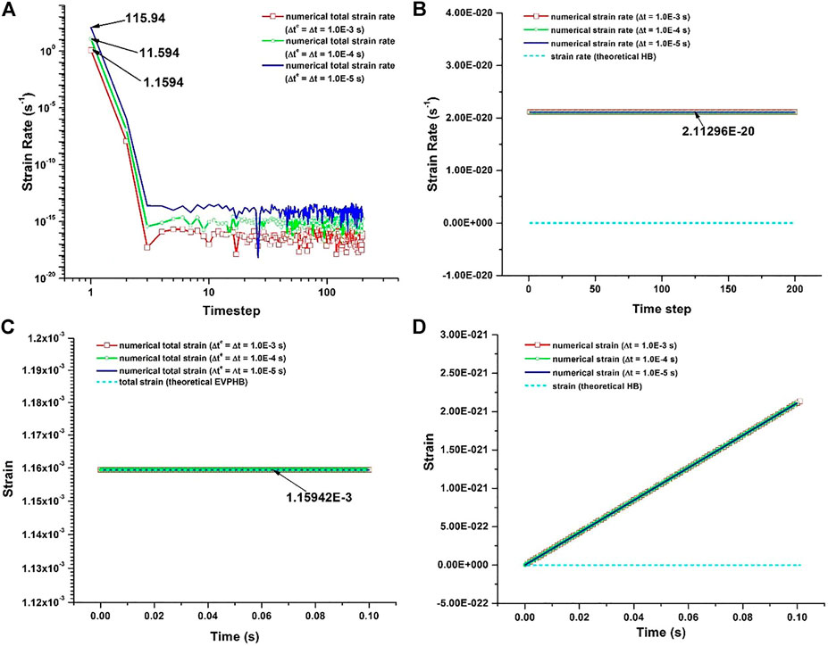
FIGURE 3. Shear stress lower than yield stress. The total shear strain rate and strain produced by EVPHB model were separately plotted in (A) and (C), the shear strain rate and strain produced by RHB model were separately plotted in (B) and (D).
RHB model also produces a very small shear strain rate of value about 10−20 s−1 (Figure 3B), which is very close to the 0 value expected for a pure Herschel-Bulkley model, and which is caused in this case by the regularization. This small value integrated over 0.1 s (Figure 3D) only produces a strain increment about 3.1×10⁻²¹, and the fluid under yield stress can effectively be considered as rigid with the very large value of regularization parameter m used here, in contrary to the EVPHB model for which the total strain is finite and due to elasticity.
3.1.2 Shear stress boundary condition larger than yield stress
For a constant boundary stress (100 Pa) which is larger than the yield stress of the studied material (91 Pa), the shear strain rate initiates with a very high value in the first timestep, and reaches the theoretical shear strain rate (0.00363 s−1) from the second step regardless of the timestep value (Figure 4A). The cause for the initial jump of shear strain rate is the same as in Figure 3A, due to the initial stress change from 0 Pa to 100 Pa which produce a great elastic strain rate in the EVPHB model. As previously, it is also observed that the length of timestep influences the initial shear strain rate which decreases from 144.92754 s−1 to 1.4492754 s−1 for different timesteps from 10−5 s to 10−3 s. After the first time step, the stress is constant (stress rate is 0) and therefore, according to Eq. 6, only a viscous strain rate (of theoretical value 0.00363 s−1) is produced from the second timestep on. Hence, as expected, the elastic strain (black dot) is formed in the first timestep and thereafter keeps constant as shown in Figure 4C. Since the constant stress produces a constant viscous strain rate, the corresponding viscous strain (pink dot) increases linearly in time. It is also clear that regardless of the timestep value, the numerical strain produced by EVPHB model is the same as the theoretical value, which validates the proper implementation of EVPHB model in FEMLIP.
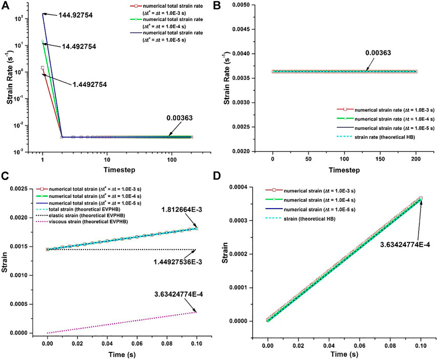
FIGURE 4. Shear stress larger than yield stress. The total shear strain rate and strain produced by EVPHB model were separately plotted in (A) and (C), shear strain rate and strain produced by RHB model were separately plotted in (B) and (D).
For RHB model (Figure 4B), a purely viscous strain rate with a value perfectly agreeing with the theoretical value (0.00363 s−1) calculated from Eq. 3 is obtained, irrespective of the length of the timestep. Accordingly the viscous strain linearly increased in Figure 4D, and for different timesteps the numerical strain is exactly the same as the theoretical prediction. It is also found that for the same stress condition, the strain produced by RHB model is much smaller than that produced by EVPHB model, due to the absence of elastic behavior in the former.
3.1.3 Heterogeneous shear layer in a gravity-driven flow
A second benchmark was designed to verify the implementation of the EVPHB model. It consists of an infinite layer of material of thickness H flowing in steady regime under gravity on a slope of angle α as shown in Figure 5. This configuration is characterized by heterogeneous stress, strain and strain rate distributions in the depth direction. In Figure 5 the green part represents the unsheared plug layer where the shear stress τ is lower than the yield stress τ0, while the red part is the sheared layer where τ > τ0. In the simulations, a square of material with a length of H is defined, and the effect of infinite length is produced by periodic boundaries in x direction. The distribution of shear stress in the depth of the flow layer is linear, and can be calculated by Eq. 19, in which (H-z) is the depth in z direction. The condition at the base of the flow is supposed to be non-slip. Associated with the equations of Herschel-Bulkley model (Eqs. 1–3) and with a straightforward integration, the theoretical distributions of velocity, strain rate and strain in the depth direction can be calculated: see Eqs. 20–23, where h0 is the thickness of the plug layer at the top of the flowing layer and v(z) is the velocity at depth (H-z).
when
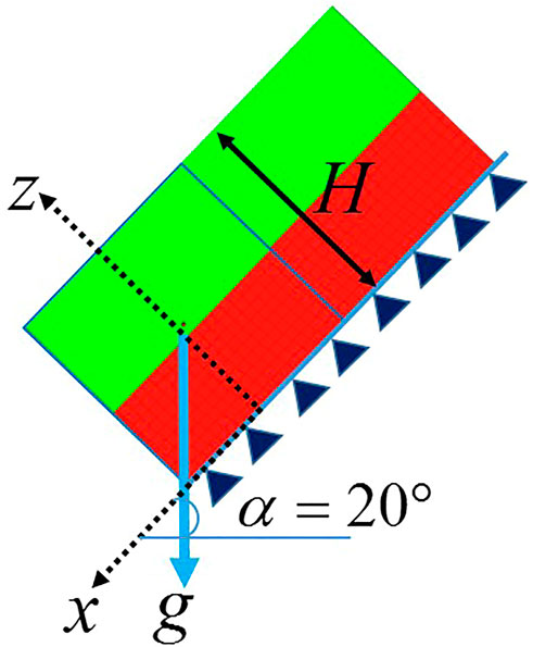
FIGURE 5. Flow of infinite layer under gravity on a slope. The green (resp. red) area represents the plug (resp. sheared) layer in the steady solution, as computed with the EVPHB model.
Using the parameters of K55 in Table 1, we considered an infinite layer with a depth of H = 0.03 m flowing on a slope of 20°, and
In Figure 6 the stress, velocity, shear strain rate and strain were sampled in the depth direction (z) after 1000 timesteps (at time 0.01 s). The theoretical thicknesses of plug and sheared layers are also indicated. First, Figure 6A shows the linear increase of stress in depth direction: for both EVPHB and RHB models the numerical results are identical to theoretical predictions. From this distribution, the depth of plug layer is calculated to be 0.01336 m according to value of the yield stress (91Pa). In Figures 6B,C the velocity and shear strain rate produced by EVPHB and RHB models also seem perfectly collapse onto the results calculated by Eqs. 21–23. In the plug layer or solid zone, the velocity is uniformly distributed, while in the sheared layer or fluid zone the velocity in the vicinity of yield surface first has a very slow decrease and after a short distance rapidly decreases to zero at the bottom. Similar plug shape is also observed in Figure 6C for the shear strain rate distribution, where it is clear that in the plug layer shear strain rate is 0, and increases to its maximum in the sheared layer at the bottom. In Figure 6D the strain produced by EVPHB model is greater than those of RHB and theoretical HB, due to the elastic deformation accounted for in EVPHB model. For RHB and theoretical HB models, the strain in the solid zone is zero and exponentially increases in the fluid zone.
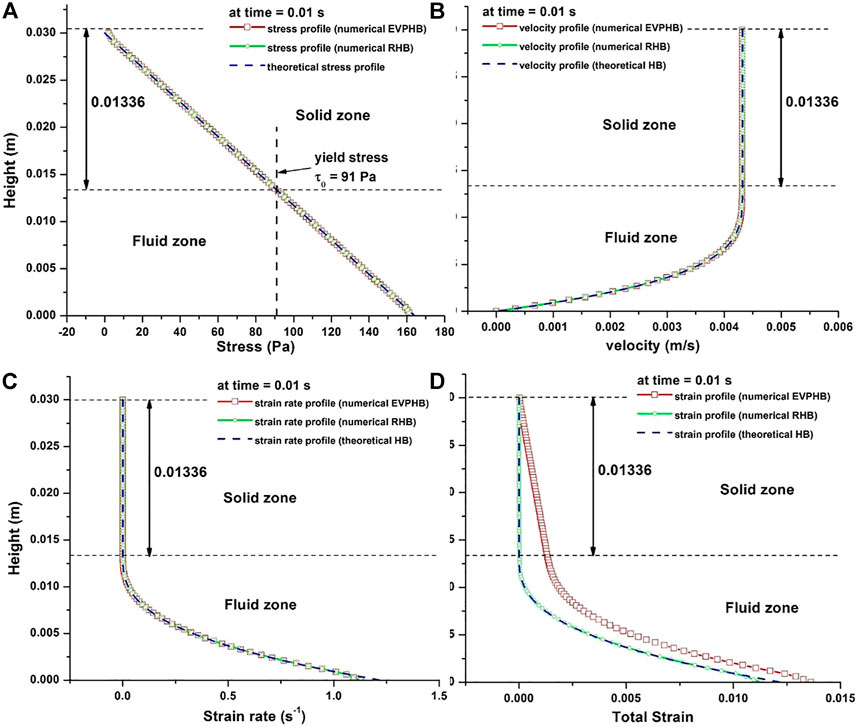
FIGURE 6. (A) Stress distribution in depth direction, (B) Velocity distribution in depth direction, (C) Shear strain rate distribution in depth direction, (D) Strain distribution in depth direction.
In Figure 6 because of the linear coordinate system, the layer thicknesses obtained with EVPHB and RHB have nearly negligible difference. A specific comparison of the plug layer thickness obtained with EVPHB and RHB model is portrayed in a logarithm coordinate system in Figure 7.
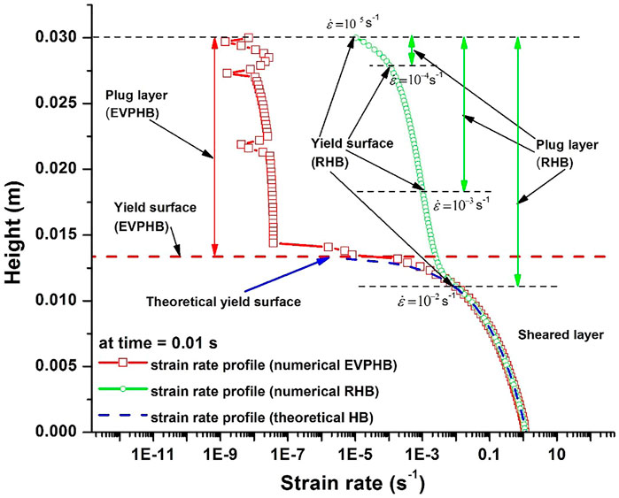
FIGURE 7. Yield surface determined with EVPHB and RHB models. For RHB model, the apparent yield surface corresponding to different strain rate threshold are indicated.
Since in FEMLIP the stress state of each particle can be tracked, it is natural for EVPHB model to define the solid or fluid state of a particle according to the yield stress criterion, and to derive the plug thickness accordingly. Particle was in solid state when its stress was within the yield stress. Then all the particles in solid state can be obtained to calculate the plug thickness. As expected, in Figure 7, the plug thickness obtained with EVPHB model is therefore in excellent agreement with the theoretical value. On the contrary, with RHB model, an arbitrary threshold on strain rate has to be chosen, which is generally not very accurate due to the smooth shape of the profiles at the transition. For instance the apparent yield surfaces respectively determined by a strain rate of 10−5, 10−4, 10−3 and 10−2 s−1 with RHB model are shown in Figure 7, all of them lying apart from the theoretical plug layer interface. The more accurate tracking of the plug zone through a stress criterion here clearly appears as an advantage of EVPHB model over RHB model.
It is also worthy of note that the strain rate in the plug layer produced by EVPHB model is here smaller than that produced by RHB model, unlike what was observed in Figures 3A,B for the homogeneous shear test. These non-negligible strain rate values produced here by RHB model are clearly related to the value of the regularization parameter m, which cannot be chosen arbitrarily large for the sake of avoiding ill-conditioned matrix. In other words, for a practical simulation, such as any free surface simulations, to insure the priority of successful and accurate numerical solution, EVPHB model has more advantage over RHB model.
From the evolutions of stress, strain rate and strain sampled in the depth direction, the relations between stress and strain, and between stress and strain rate can be reconstructed (Figures 8A,B). As shown in Figure 8A, in the solid zone the stress and strain produced by EVPHB model are linearly dependent (red square line), and consistent with the theoretical elastic constitutive law (blue dash line), i.e. EVPHB model is effectively capable to describe elastic deformation when stress is below yield stress. On the contrary, nearly no strain is produced by RHB model in the solid zone (green square line); in other words, this model treats the material as nearly rigid when stress is below yield stress. In the fluid zone, because of elasticity the two EVPHB and RHB models produce different strains.
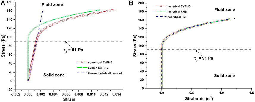
FIGURE 8. (A) Stress and strain relation in depth direction, (B) Stress and shear strain rate relation in depth direction.
In Figure 8B, in the fluid zone the stress and shear strain rate curves produced by both EVPHB and RHB models well collapse onto the theoretical HB constitutive curve, which indicates that both models can represent Herschel-Bulkley relation. In the solid zone, in spite of the stress changes, the strain rate is nearly zero. Therefore, from Figures 8A,B it is again reasonable to conclude that the EVPHB model is capable to accurately describe both elastic (linear stress and strain relation) and viscous (nonlinear stress and strain rate relation) deformations in a flow and that there are remarkable differences between EVPHB and RHB models.
3.2 Simple shear test with time-dependent boundary conditions
3.2.1 Varying shear stress boundary condition
Previous analyses indicate that for a constant stress condition, the elastoviscoplastic traits of a yield stress fluid could be well represented. In this section the response of EVPHB model to a variable stress condition is investigated by continuously changing the boundary stress shown in Figure 2. In Figure 9A, the whole boundary stress variation process is divided into 6 segments numbered from I to VI. The stress increases from 80 Pa to 104 Pa at a rate of 10 Pa/s, and then decreases back at the same rate. The boundary stress in segments I and VI is constant, variable but below the yield stress in segments II and V, and above the yield stress in segments III and IV.
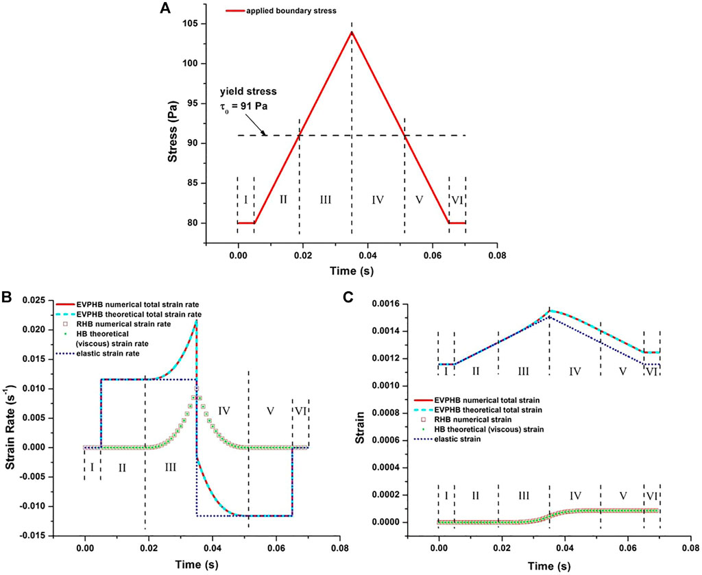
FIGURE 9. (A) Boundary stress development in a time-dependent shear flow, (B) Strain rate development produced by both EVPHB and RHB models, (C) Strain development produced by both EVPHB and RHB models.
For different stress and stress rate values, the corresponding strain rate and strain are produced by EVPHB and RHB models in different ways, as demonstrated in Figures 9B,C. For EVPHB model, the numerical total strain rate (red line) fully collapses onto the theoretical total strain rate (shallow blue dash line) calculated from Eqs. 5, 6. For RHB model the numerical strain rate (red square) also well collapses onto the theoretical (HB) viscous strain rate (green dot) calculated from Eqs. 1, 3. It is noteworthy that when stress is below the yield stress, the strain rate produced by RHB model is negligible, which indicates that by choosing a proper regularization parameter in Eq. 4, the RHB model can represent an almost rigid material. Similarly, Figure 9C shows that the numerical total strain produced by EVPHB (red line) and RHB models (red square) well agree with the corresponding theoretical values (shallow blue dash line and green dots, respectively).
The most significant difference between EVPHB and RHB models is the addition of elasticity, which makes EVPHB model produce both elastic and viscous deformations. In order to show this difference, the theoretical elastic strain and strain rate are calculated according to the corresponding boundary stress and separately plotted in Figures 9B,C (blue dots). As expected, regardless of whether the stress is below or above the yield stress, as soon as it is it is not constant the elasticity always produces an elastic strain rate in Figure 9B, and consequently an elastic strain in Figure 9C. What is also clearly portrayed by Figure 9B is that for EVPHB model the total strain rate (red line or shallow blue dash line) is the sum of elastic (blue dot) and viscous (green dot) components, which is also true for the strain in Figure 9C.
3.2.2 Relaxation under constant strain
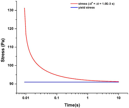
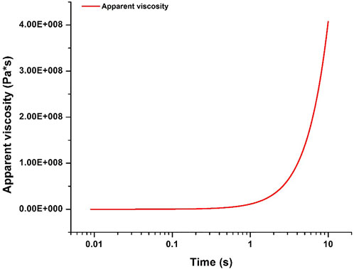
From Eq. 6, it is seen that when stress is above yield stress, EVPHB model is basically a Maxwell model. In other words, under a constant boundary strain condition, EVPHB model is expected to result in a stress relaxation process. This is verified by applying a constant boundary strain (2.33333×10⁻³) on the top of the square shown in Figure 2. In this shear test, the constant boundary strain was achieved by applying a constant boundary velocity (0.007 m/s) for 0.009 s, after which the boundary velocity is set to be 0. Figure 10 shows the corresponding stress response, characterized by a sharp decrease from a value greater than 130 Pa–91 Pa (yield stress) in less than 10 s, unlike in a classical Maxwell-type stress relaxation, the final stress keeps constant after reaching the yield stress. This is because once the stress is below the yield stress, EVPHB model reduces to a pure elastic model, i.e. only when stress is above the yield stress does EVPHB model show time-dependent behavior. The characteristic relaxation time cannot be theoretically calculated since the apparent viscosity of EVPHB model (η′ in Eq. 6) is strain-rate-dependent, and thus here time-dependent, as shown in Figure 11. At the beginning of stress relaxation, the apparent viscosity is almost relatively small, and then sharply increases with time since the strain rate progressively gets smaller as the stress gets closer to the yield stress.
4 Conclusion
On the basis of a comprehensive review of the current viscoplastic models and elastoviscoplastic models proposed for yield stress fluids, a complete elastoviscoplastic Herschel-Bulkley model was considered in this numerical study. The three-dimensional form of the elastoviscoplastic Herschel-Bulkley model (EVPHB) was derived, and the resolution of EVPHB model in Finite Element Method with Lagrangian Integration Points was developed. As a comparison, a regularized Herschel-Bulkley model (RHB) was also implemented in FEMLIP to demonstrate how the elasticity makes the EVPHB model distinctive. The conclusions are summarized as follows:
1) Finite Element Method with Lagrangian Integration Points (FEMLIP) method is suitable for the solution of elastoviscoplastic Herschel-Bulkley model, as well as for regularized Herschel-Bulkley model. The implementation of EVPHB and RHB models are verified to be correct by using four boundary value problems. FEMLIP approach makes the difference over classical numerical method since elastic stresses stored on material points must be carried out over a long distance.
2) In the simple shear tests with constant applied stress and the heterogeneous gravity-driven flow test, the EVPHB model could reproduce the theoretical elastic strain and stress-strain constitutive relation when stress is below yield stress; when stress is above yield stress, it could reproduce a Herschel-Bulkley stress - strain rate constitutive relation.
3) Since FEMLIP provides the tracing of particle stress and other historical variables and EVPHB model could define the solid or fluid state of a particle according to stress criteria, EVPHB model shows the capability of a more accurate tracking of plug zones over RHB model. For practical simulations, such as free surface simulations, the regularization parameter used in RHB model could not be chosen too large to avoid ill-conditioned matrix, which impedes the accurate determination of plug zones.
4) For a time-dependent boundary stress, the elasticity included in the EVPHB model makes the material under shear experience a deformation process which is significantly distinctive from the deformation process produced by the RHB model. The strain and strain rate produced by EVPHB model includes both elastic and viscous components. EVPHB model also results in a stress relaxation process for materials under constant strain conditions. In this relaxation process, with time going on, the stress first sharply decreases from its initial value above the yield stress, and then slowly reaches the yield stress.
Data availability statement
The original contributions presented in the study are included in the article/supplementary material, further inquiries can be directed to the corresponding author.
Author contributions
BZ contributed to conception and investigation of the study and wrote the first draft of the manuscript. All authors contributed to manuscript revision, read, and approved the submitted version.
Funding
This study was funded by the National Key R&D Program of China, grant number 2018YFC0809400.
Conflict of interest
Authors BZ, YC, YL, XK, ZY, RT, XX and YD were employed by China Electric Power Research Institute Co., Ltd.
Publisher’s note
All claims expressed in this article are solely those of the authors and do not necessarily represent those of their affiliated organizations, or those of the publisher, the editors and the reviewers. Any product that may be evaluated in this article, or claim that may be made by its manufacturer, is not guaranteed or endorsed by the publisher.
References
Adams, M. J., Aydin, İ., Briscoe, B. J., and Sinha, S. K. (1997). A finite element analysis of the squeeze flow of an elasto-viscoplastic paste material. J. Nonnewt. Fluid Mech. 71, 41–57. doi:10.1016/s0377-0257(96)01546-7
Alexandrou, A. N., McGilvreay, T. M., and Burgos, G. (2001). Steady Herschel–Bulkley fluid flow in three-dimensional expansions. J. Nonnewt. Fluid Mech. 100, 77–96. doi:10.1016/s0377-0257(01)00127-6
Ancey, C. (2007). Plasticity and geophysical flows: A review. J. Nonnewt. Fluid Mech. 142, 4–35. doi:10.1016/j.jnnfm.2006.05.005
Balmforth, N. J., Frigaard, I. A., and Ovarlez, G. (2014). Yielding to stress: Recent developments in viscoplastic fluid mechanics. Annu. Rev. Fluid Mech. 46, 121–146. doi:10.1146/annurev-fluid-010313-141424
Bardenhagen, S. G., and Kober, E. M. (2004). The generalized interpolation material point method. Comput. Model. Eng. Sci. 5, 477–496.
Bénito, S., Bruneau, C. H., Colin, T., Gay, C., and Molino, F. (2008). An elasto-visco-plastic model for immortal foams or emulsions. Eur. Phys. J. E 25, 225–251. doi:10.1140/epje/i2007-10284-2
Blackery, J., and Mitsoulis, E. (1997). Creeping motion of a sphere in tubes filled with a Bingham plastic material. J. Nonnewt. Fluid Mech. 70, 59–77. doi:10.1016/s0377-0257(96)01536-4
Burgos, G. R., Alexandrou, A. N., and Entov, V. (1999). On the determination of yield surfaces in Herschel–Bulkley fluids. J. Rheol. (N. Y. N. Y). 43, 463–483. doi:10.1122/1.550992
Chambon, G., Ghemmour, A., and Laigle, D. (2009). Gravity-driven surges of a viscoplastic fluid: An experimental study. J. Nonnewt. Fluid Mech. 158, 54–62. doi:10.1016/j.jnnfm.2008.08.006
Chambon, G., Ghemmour, A., and Naaim, M. (2014). Experimental investigation of viscoplastic free-surface flows in a steady uniform regime. J. Fluid Mech. 754, 332–364. doi:10.1017/jfm.2014.378
Cheddadi, I., Saramito, P., and Graner, F. (2012). Steady Couette flows of elastoviscoplastic fluids are nonunique. J. Rheol. (N. Y. N. Y). 56, 213–239. doi:10.1122/1.3675605
Coussot, P., and Piau, J. M. (1994). On the behavior of fine mud suspensions. Rheol. Acta 33, 175–184. doi:10.1007/BF00437302
Cuomo, S., Prime, N., Iannone, A., Dufour, F., Cascini, L., and Darve, F. (2013). Large deformation FEMLIP drained analysis of a vertical cut. Acta Geotech. 8, 125–136.
de Souza Mendes, P. R., Naccache, M. F., Varges, P. R., and Marchesini, F. H. (2007). Flow of viscoplastic liquids through axisymmetric expansions–contractions. J. Nonnewt. Fluid Mech. 142, 207–217. doi:10.1016/j.jnnfm.2006.09.007
Donea, J., Giuliani, S., and Halleux, J.-P. (1982). An arbitrary Lagrangian-Eulerian finite element method for transient dynamic fluid-structure interactions. Comput. Methods Appl. Mech. Eng. 33, 689–723. doi:10.1016/0045-7825(82)90128-1
Dufour, F., and Pijaudier‐Cabot, G. (2005). Numerical modelling of concrete flow: Homogeneous approach. Int. J. Numer. Anal. methods Geomech. 29, 395–416. doi:10.1002/nag.419
Fernández-Nieto, E. D., Gallardo, J. M., and Vigneaux, P. (2014). Efficient numerical schemes for viscoplastic avalanches. Part 1: The 1D case. J. Comput. Phys. 264, 55–90. doi:10.1016/j.jcp.2014.01.026
Harlow, F. H. (1964). The particle-in-cell computing method for fluid dynamics. Methods comput. Phys. 3, 319–343.
Herschel, W. H., and Bulkley, R. (1926). Measurement of consistency as applied to rubber-benzene solutions. Am. Soc. Test. Proc. 16, 621–633.
Hirt, C. W., Amsden, A. A., and Cook, J. L. (1974). An arbitrary Lagrangian-Eulerian computing method for all flow speeds. J. Comput. Phys. 14, 227–253. doi:10.1016/0021-9991(74)90051-5
Huang, X., and García, M. H. (1999). Modeling of non-hydroplaning mudflows on continental slopes. Mar. Geol. 154, 131–142. doi:10.1016/S0025-3227(98)00108-X
Huilgol, R. R., and You, Z. (2005). Application of the augmented Lagrangian method to steady pipe flows of Bingham, Casson and Herschel-Bulkley fluids. J. Nonnewt. Fluid Mech. 128, 126–143. doi:10.1016/j.jnnfm.2005.04.004
Idelsohn, S. R., Marti, J., Becker, P., and Oñate, E. (2014). Analysis of multifluid flows with large time steps using the particle finite element method. Int. J. Numer. Methods Fluids 75, 621–644. doi:10.1002/fld.3908
Idelsohn, S. R., Nigro, N. M., Gimenez, J. M., Rossi, R., and Marti, J. M. (2013). A fast and accurate method to solve the incompressible Navier‐Stokes equations. Eng. Comput. Swans. 30, 197–222. doi:10.1108/02644401311304854
Idelsohn, S. R., Onate, E., and Del Pin, F. (2004). The particle finite element method: A powerful tool to solve incompressible flows with free-surfaces and breaking waves. Int. J. Numer. Methods Eng. 61, 964–989. doi:10.1002/nme.1096
Isayev, A. I., and Fan, X. (1990). Viscoelastic plastic constitutive equation for flow of particle filled polymers. J. Rheol. (N. Y. N. Y). 34, 35–54. doi:10.1122/1.550113
Knupp, P., Margolin, L. G., and Shashkov, M. (2002). Reference Jacobian optimization-based rezone strategies for arbitrary Lagrangian Eulerian methods. J. Comput. Phys. 176, 93–128. doi:10.1006/jcph.2001.6969
Laigle, D., and Coussot, P. (1997). Numerical modeling of mudflows. J. Hydraul. Eng. 123, 617–623. doi:10.1061/(asce)0733-9429(1997)123:7(617)
Lenardic, A., and Kaula, W. M. (1993). A numerical treatment of geodynamic viscous flow problems involving the advection of material interfaces. J. Geophys. Res. 98, 8243–8260. doi:10.1029/92jb02858
Liu, W. B., and Barrett, J. W. (1994). Quasi-norm error bounds for the finite element approximation of some degenerate quasilinear elliptic equations and variational inequalities. ESAIM Math. Model. Numer. Anal. 28, 725–744. doi:10.1051/m2an/1994280607251
Locat, J. (1997). “Normalized rheological behaviour of fine muds and their flow properties in a pseudoplastic regime,” in Debris-flow hazards mitigation: Mechanics, prediction, and assessment (ASCE) (Rotterdam, Netherlands: Millpress Science Publishers), 260–269.
Luu, L. H., and Forterre, Y. (2009). Drop impact of yield-stress fluids. J. Fluid Mech. 632, 301–327. doi:10.1017/S0022112009007198
Margolin, L. G. (1997). Introduction to “An arbitrary Lagrangian-Eulerian computing method for all flow speeds. J. Comput. Phys. 135, 198–202. doi:10.1006/jcph.1997.5727
Marmottant, P., and Graner, F. (2007). An elastic, plastic, viscous model for slow shear of a liquid foam. Eur. Phys. J. E 23, 337–347. doi:10.1140/epje/i2006-10193-x
Mitsoulw, E., Abdali, S., Fluid, C., and Unit, D. (1993). Flow simulation of herschel-bulkley fluids through extrusion dies. Can. J. Chem. Eng. 71, 147–160. doi:10.1002/cjce.5450710120
Moresi, L., Dufour, F., and Mühlhaus, H.-B. (2003). A Lagrangian integration point finite element method for large deformation modeling of viscoelastic geomaterials. J. Comput. Phys. 184, 476–497. doi:10.1016/s0021-9991(02)00031-1
Moresi, L., and Solomatov, V. S. (1995). Numerical investigation of 2D convection with extremely large viscosity variations. Phys. Fluids 7, 2154–2162. doi:10.1063/1.868465
Muravleva, L., Muravleva, E., Georgiou, G. C., and Mitsoulis, E. (2010). Numerical simulations of cessation flows of a Bingham plastic with the augmented Lagrangian method. J. Nonnewt. Fluid Mech. 165, 544–550. doi:10.1016/j.jnnfm.2010.02.002
Oldroyd, J. G. (1950). On the formulation of rheological equations of state. Proc. R. Soc. Lond. Ser. A. Math. Phys. Sci. 200, 523–541.
Olshanskii, M. A. (2009). Analysis of semi-staggered finite-difference method with application to Bingham flows. Comput. Methods Appl. Mech. Eng. 198, 975–985. doi:10.1016/j.cma.2008.11.010
Papanastasiou, T. C., and Boudouvis, A. G. (1997). Flows of viscoplastic materials: Models and computations. Comput. Struct. 64, 677–694. doi:10.1016/S0045-7949(96)00167-8
Papanastasiou, T. C. (1987). Flows of materials with yield. J. Rheol. (N. Y. N. Y). 31, 385–404. doi:10.1122/1.549926
Perzyna, P. (1962). The constitutive equations for rate sensitive plastic materials. Q. Appl. Math. 20, 321–332. doi:10.1090/qam/144536
Prime, N., Dufour, F., and Darve, F. (2014). Unified model for geomaterial solid/fluid states and the transition in between. J. Eng. Mech. 140. doi:10.1061/(asce)em.1943-7889.0000742
Puzrin, A. M., and Houlsby, G. T. (2003). Rate-dependent hyperplasticity with internal functions. J. Eng. Mech. 129, 252–263. doi:10.1061/(asce)0733-9399(2003)129:3(252)
Roquet, N., and Saramito, P. (2008). An adaptive finite element method for viscoplastic flows in a square pipe with stick-slip at the wall. J. Nonnewt. Fluid Mech. 155, 101–115. doi:10.1016/j.jnnfm.2007.12.003
Saramito, P. (2007). A new constitutive equation for elastoviscoplastic fluid flows. J. Nonnewt. Fluid Mech. 145, 1–14. doi:10.1016/j.jnnfm.2007.04.004
Saramito, P. (2009). A new elastoviscoplastic model based on the Herschel–Bulkley viscoplastic model. J. Nonnewt. Fluid Mech. 158, 154–161. doi:10.1016/j.jnnfm.2008.12.001
Saramito, P., and Roquet, N. (2001). An adaptive finite element method for viscoplastic fluid flows in pipes. Comput. Methods Appl. Mech. Eng. 190, 5391–5412. doi:10.1016/s0045-7825(01)00175-x
Sousa, J., and Voight, B. (1991). Continuum simulation of flow failures. Geotechnique 41, 515–538. doi:10.1680/geot.1991.41.4.515
Sulsky, D., Chen, Z., and Schreyer, H. L. (1994). A particle method for history-dependent materials. Comput. Methods Appl. Mech. Eng. 118, 179–196. doi:10.1016/0045-7825(94)90112-0
Sulsky, D., Zhou, S.-J., and Schreyer, H. L. (1995). Application of a particle-in-cell method to solid mechanics. Comput. Phys. Commun. 87, 236–252. doi:10.1016/0010-4655(94)00170-7
Syrakos, A., Georgiou, G. C., and Alexandrou, A. N. (2013). Solution of the square lid-driven cavity flow of a Bingham plastic using the finite volume method. J. Nonnewt. Fluid Mech. 195, 19–31. doi:10.1016/j.jnnfm.2012.12.008
Takeshi, O., and Sekimoto, K. (2005). Internal stress in a model elastoplastic fluid. Phys. Rev. Lett. 95, 108301–108304. doi:10.1103/PhysRevLett.95.108301
Turan, O., Chakraborty, N., and Poole, R. J. (2012). Laminar Rayleigh-Bénard convection of yield stress fluids in a square enclosure. J. Nonnewt. Fluid Mech. 171, 83–96. doi:10.1016/j.jnnfm.2012.01.006
Van Keken, P. E., King, S. D., Schmeling, H., Christensen, U. R., Neumeister, D., and Doin, M. (1997). A comparison of methods for the modeling of thermochemical convection. J. Geophys. Res. 102, 22477–22495. doi:10.1029/97jb01353
Whipple, K. X., and Dunne, T. (1992). The influence of debris-flow rheology on fan morphology, Owens Valley, California. Geol. Soc. Am. Bull. 104, 887–900. doi:10.1130/0016-7606(1992)104<0887:TIODFR>2.3.CO;2
Keywords: debris flow, fluid, phase transition, numerical simulation, yield stress
Citation: Zhao B, Cheng Y, Liu Y, Kong X, Yang Z, Tong R, Xu X and Deng Y (2022) Investigation of the numerical simulation of debris flow fluid with concern of phase transition. Front. Earth Sci. 10:982332. doi: 10.3389/feart.2022.982332
Received: 30 June 2022; Accepted: 30 August 2022;
Published: 29 September 2022.
Edited by:
Xiaojun Guo, Institute of Mountain Hazards and Environment (CAS), ChinaReviewed by:
Lin Zhang, Hohai University, ChinaPo Ning, Institute of Mountain Hazards and Environment (CAS), China
Copyright © 2022 Zhao, Cheng, Liu, Kong, Yang, Tong, Xu and Deng. This is an open-access article distributed under the terms of the Creative Commons Attribution License (CC BY). The use, distribution or reproduction in other forums is permitted, provided the original author(s) and the copyright owner(s) are credited and that the original publication in this journal is cited, in accordance with accepted academic practice. No use, distribution or reproduction is permitted which does not comply with these terms.
*Correspondence: Binbin Zhao, MTIzemhhb2JpbmJpbkAxNjMuY29t
 Binbin Zhao
 Yongfeng Cheng1
 Xiaoang Kong