 Zubin Ai1
 Huajin Zhang
 Shunchuan Wu
95% of researchers rate our articles as excellent or good
Learn more about the work of our research integrity team to safeguard the quality of each article we publish.
Find out more
ORIGINAL RESEARCH article
Front. Earth Sci. , 15 September 2022
Sec. Geohazards and Georisks
Volume 10 - 2022 | https://doi.org/10.3389/feart.2022.981503
This article is part of the Research Topic Rock Landslide Risk Assessment, Stability Analysis and Monitoring for The Development of Early Warning Systems and Reinforcement Measures View all 24 articles
The strength of a rock-soil mass shows complex and obvious weakening characteristics under seismic dynamic load. The previous stability analysis methods of a seismic slope do not fully depict the attenuation law of geotechnical materials and cannot truly reflect the stable state of a slope under earthquake action. Based on the theoretical analysis of the progressive failure mechanism and the evolution law of a seismic slope, the adverse effect of progressive failure on slope stability is clarified. According to the progressive failure process of a slope under dynamic load, the strain-softening model and vibration deterioration model are introduced to represent the attenuation law of rock strength parameters, and a calculation method of seismic slope stability coupled with vibration disturbance and progressive failure is proposed. The method considers the strength parameter characteristics of a rock-soil mass in different stages and is combined with the vector sum method to obtain the time-history curve of the slope safety factor under earthquake action, which makes the evaluation result of slope stability more accurate and reliable. The numerical examples show that this method can effectively reflect the dynamic stability of seismic slopes, and solve the problem that the traditional calculation methods are difficult to characterize the strength attenuation characteristics of rock and soil mass. If these characteristics are not considered, the calculation results will be unsafe.
Slopes exist widely in the fields of water conservancy and civil engineering, and many large-scale projects are constructed in areas where earthquakes frequently occur (Xu and Xu. 2013). At present, global seismic activity is experiencing a relatively active period. According to the statistics, there were 115 earthquakes above six magnitudes in 2021. A serious destructive earthquake can easily trigger deadly landslides. Once a slope is damaged during an earthquake, many casualties may occur, and the economy will suffer severe losses (Valentin et al., 2016; Ma et al., 2021).
To avoid or reduce landslide disasters triggered by earthquakes, accurate evaluation of slope stability under earthquake action is the theoretical foundation of disaster prevention and anti-seismic supporting systems design (Du et al., 2022). The current seismic slope stability analysis methods mainly include theoretical analysis, numerical simulation and model test (Zhang et al., 2021; Yu et al., 2022). Numerical simulation offers the advantages of repeatability, time-saving, high efficiency, and low cost and has received widespread attention of scholars around the world. This category includes the pseudo-static method (Baker et al., 2006) and the seismic time-history analysis method (Pang et al., 2021). In the pseudo-static method, the dynamic inertia force of an earthquake is simplified as the product of the constant acceleration in the horizontal and vertical directions and the slope mass; then the static safety factor is solved generally with the limit equilibrium theory. This simple and convenient method has been widely applied in the stability analysis of seismic slopes (Karray et al., 2018; Zhao et al., 2020). However, it neglects the dynamic nonlinear behavior and evolution law of rock-soil mass and cannot reflect the mechanical response of a slope under cyclic load (Macedo and Candia 2020). After comparing the difference in calculation results of the pseudo-static method and the nonlinear dynamic approach, Bolla and Paronuzzi (2021) believed that the former was not suitable for the dynamic stability analysis of a rock slope. In the seismic time-history analysis method, the safety factor of each dynamic step is obtained through the dynamic stress field of the slope during the earthquake duration. This method can reflect the evolution of the dynamic process over the duration of the seismic event. The results of the time-history analysis method are more realistic and abundant and have gradually come to occupy a dominant position in the numerical analysis of seismic slope stability (Guo et al., 2011; Koo et al., 2016).
In the numerical simulation of the seismic slope, applying the peak or residual strength of a rock-soil mass for design and analysis will cause landslide hazards or unnecessary supporting waste. Therefore, it is of great significance to evaluate the slope stability with a reasonable and reliable constitutive model, of which the determination depends on the failure mechanism and essential features of the seismic slope. Due to the dynamic cyclic loads of earthquakes, the failure features of dynamic slopes tend to be more complex than static slopes. The failure mechanism of the slope under the earthquake can be summarized in two aspects (Eberhardt et al., 2004; Song et al., 2020; Negi et al., 2022). 1) The dynamic cyclic load reduces the strength parameters of a rock-soil mass, making the anti-sliding force of the slope smaller. For natural or man-made reasons, when the cyclic loading acts on the rock and soil, it may lead to the slow deterioration of strength and fatigue failure. Wang Y. et al. (2010) carried out uniaxial tensile tests on granite under cyclic loading, and the research showed that the dynamic strength under cyclic loading was lower than the failure strength under monotone loading. With an increase of cycling times, the rock damage and softening phenomenon occurred. 2) Under various adverse factors, slope failure is a progressive process from intact to local damage to overall penetration failure (Du et al., 2020). Many scholars believe that the dynamic failure mechanism of seismic slopes is that the cracks first appear in the structural plane or slope foot (local damage), then expand, deepen and penetrate with the continuous seismic hit, causing further damage to the surrounding rock mass. Finally, the seismic slope develops to the overall penetration failure, which shows that the entire sliding surface is penetrated (Song et al., 2020). Quinn et al. (2012) analyzed the progressive failure development of clay slope and the relationship between the failure surface and vibration time, indicating that the cyclic load caused by earthquakes makes the developing failure surface propagate freely toward overall failure.
Using the dynamic load mechanism, many scholars have examined the numerical relationship between the slope failure mechanism and strain-softening features and suggested the strain-softening model, which successfully captures the progressive slope failure features (Di et al., 2017; Wang et al., 2021). These results show that considering the strain-softening features of a rock-soil mass can provide a reasonable simulation of the slope failure process. The strain-softening model is widely used in slope stability analysis, but it only reflects the elastoplastic variation features of rock-soil mass strength, ignoring the vibration deterioration effect of the potential slip surface of a seismic slope under dynamic load. Actually, after the failure surface of the slope is generated, the residual strength of the rock mass (especially the friction force) still provides a large anti-slip force. Under the cyclic shear action of a dynamic load, wear and passivation will inevitably lead to further attenuation of the residual shear strength parameters of the failure surface (Cao et al., 2008). Some scholars have carried out dynamic cyclic shear tests on the structural planes of rock mass and analyzed the deterioration law of structural plane strength, indicating that cyclic shear load greatly reduces the shear strength of joints (Lee et al., 2001; Jafari et al., 2004). Based on the classical wear theory, Li et al. (2019) proposed a constitutive model for the shear characteristics of rock joints under cyclic loads, which is more practical than empirical models and can quantitatively evaluate the shear characteristics of rock joints with asperity degradation and debris backfilling. Ni et al. (2013) proposed a vibration deterioration model of the structural plane through a cyclic shear test, but the calculation method of this model is only applicable to the original joints, not to the secondary joints generated in the failure process. Under the cyclic shear of a dynamic load, the phenomenon of abrasion and passivation will inevitably lead to the reduction of the shear strength parameters, subsequently further weakening the stability of a rock-soil mass and directly inducing landslides (Fan et al., 2017).
The failure process of the rock-soil mass in a seismic slope is of complexity that during the progressive failure process, the geotechnical materials at different positions may be in the peak, softening, or residual state, accompanied by the vibration deterioration phenomenon of the original joints and secondary cracks. The pre-existing research findings neither effectively reflect the strength weakening law of a rock-soil mass during the earthquake nor fully consider the strain-softening and vibration deterioration features of a seismic slope. Therefore, based on the failure mechanism of earthquake slope, the progressive failure process of slip surface and its influence on slope stability are discussed in this article under earthquake. A stability calculation method of the seismic slope is proposed that considers slip surface progressive failure, combined with the vector sum method of dynamic time-history analysis. This calculation integrates the dual factors of strain-softening and vibration deterioration under the earthquake in the process of dynamic slope stability analysis. In this method, the corresponding constitutive relation is endowed according to the state of the geotechnical materials and can improve the accuracy and reliability of calculation results.
Wang J. et al. (2010) found that the slope instability is composed of top tension and foot shear damage through the slope survey results and numerical simulation in Wen Chuan. Shinoda et al. (2015) found that obvious tension cracks exist at the rear edge of the dynamic slope based on the shaking table model test. Zhou et al. (2019) developed a closed-form method to assess the seismic stability of slopes with zero tensile strength. The aforementioned research results show that during the process of slope instability damage under the seismic dynamic load, both shear damage and tension damage occur, as shown in Figure 1.
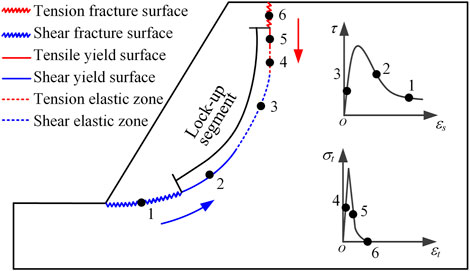
FIGURE 1. Sketch of progressive failure of the slope.
Suppose that points 1 to 6 of Figure 1 are on the potential slip surface, where points 1 and 6 are in the shearing and tension failure stages, respectively, forming the failure surface. Points 2 and 5 are in the shearing and tension plasticity stages, respectively, and the strength parameters of the rock-soil mass change with strain. Points 3 and 4 are in the elastic stage, and the strength parameters remain the same (Wang et al., 2018). The plastic and elastic section of the potential slip surface is defined as the lock-up segment. Under the action of the earthquake, the slope slip surface expands gradually from the foot and the top of the slope to the inside, the length of the lock-up segment decreases, and the degree of failure is large. Finally, the slip surfaces completely penetrate, causing the landslide disaster.
The horizontal and vertical vibration acceleration generated by the earthquake vibration leads to damage and destruction of the slip surface. Assume the additional stress F assumed by the earthquake to the slider is:
where W is the weight force of the landslide body, kN; g is gravity acceleration, g = 9.8 m/s2; and a is seismic dynamic acceleration, m/s2.
The horizontal load Fh and vertical load Fv of the dynamical load are, respectively:
where ah, and av are the horizontal and vertical direction accelerations, m/s2.
The following is based on the study of the dynamic failure of slopes under earthquakes. It is considered that the dynamic load of an earthquake generates the horizontal thrust and increases the sliding force of the slope and has a tensile effect on the slip surface. The vertical seismic load applies tension in the vertical direction to the slip surface (Che et al., 2016), as shown in Figure 2. When the concentrated stress at the end of the failure surface is greater than the crack initiation stress, the rock-soil mass will deform and damage, promoting the slope failure surface to expand inward. Then, the length of the lock-up segment in the potential slip surface decreases continuously, inducing the stability coefficient to steadily decline.
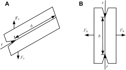
FIGURE 2. Sketch of stress concentration of slip surface. (A,B) Shear failure stage (A) and tension shear failure stage (B).
The concentrated stress of the free face is equal to the product of normal stress of the slip surface and stress concentration coefficient. According to the manual of stress concentration factors (STCM Science and Technology Committee of the Ministry of Aviation Industry, 1990), the stress concentration coefficient γ with deep gaps on one side is:
where b is the length of potential slip surface lock-up segment, m; and ρ is the curvature radius at the end of the failure surface, m.
Under the cyclic shear loadings, seismic waves result in the fragmentation of the rock-soil body and reduce the rock-soil mass integrity and strength parameters (Alfaro et al., 2012). Moreover, in the process of progressive slope damage, the failure surface still has residual strength, which can provide part of the anti-slide force. Lee et al. (2001) suggest that cyclic shear of a dynamic load will cause wear and passivation of rock mass discontinuities, and the relative velocity produced by the rock mass motion will also reduce the failure surface friction factor. As a result, the shear strength parameter of the failure surface will further attenuate under the earthquake.
According to the analysis of the aforementioned seismic slope failure process, the strain-softening and failure surface vibration deterioration models are proposed to reflect the progressive failure process of slope under the earthquake action. The progressive failure of the slope is closely related to the strain-softening characteristics of geotechnical materials. The strain-softening constitutive model can effectively simulate the progressive failure process of the slope and has been the most commonly adopted model (Wang et al., 2021). The cyclic shear action of seismic loads leads to the dynamic deterioration of the mechanical properties of the rock mass structure, which will inevitably affect the stability of the seismic slope. These influence factors are considered comprehensively in the vibration deterioration model that quantitatively describes the phenomenon of wear and passivation and can accurately characterize the change of failure surface strength under cyclic shear load (Ni et al., 2013).
Progressive failure has a great influence on the position and stability of the slip surface (Eberhardt et al., 2004). Instead of the elastoplastic model, the strain-softening model is used to simulate the characteristics of the rock-soil mass strength parameters changing with the plastic strain and to characterize the two post-failure behaviors of shear softening and tensile softening of the slope. The essence is to establish a functional relationship between strength and softening parameters in the Mohr-Coulomb yield criterion so that it can reflect the weakening of the strength parameters of geotechnical materials with the development of the yield process (Di et al., 2017).
The strain-softening model can reflect the attenuation characteristics of the rock-soil mass strength from the elastic to the failure stage, but the process is very complicated. To simplify the analysis, the simple and practical linear strain-softening Mohr-Coulomb model is adopted by most scholars (Wang et al., 2018). Based on the FLAC3D program theory in this article (Itasca 2013), we establish an attenuation function of the cumulative plastic shear strain εs and tensile strain εt as the independent variable. Cohesion c, internal friction angle φ, dilatancy angle ψ, and tensile strength σt are the dependent variables shown in Eq. 4.
This function must be obtained through a reasonable laboratory test and inversion method. The common inversion method is to input the preset attenuation function into the numerical simulation software for simulation. If the simulation results are consistent with the actual laboratory test results, the attenuation functions are considered to approach the real strain-softening curve, and the next step of slope stability analysis can be carried out. The preset attenuation function curve is represented by the linear piecewise function, as shown in Figure 3. After the plastic shear strain is generated in the rock-soil mass of the slope, the rock-soil mass shear strength parameters attenuate to the residual strength parameters until shear failure. Meanwhile, if tensile yield occurs in the rock-soil mass, the tensile strength drops to zero after the ultimate tensile strain εtf.
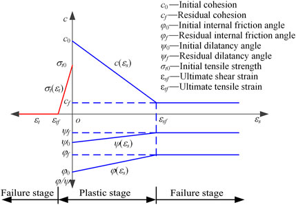
FIGURE 3. Sketch of strain-softening model strength attenuation.
The failure surface strength parameter attenuates under seismic loading, which is a complex dynamic process. According to the previous research results (Crawford and Curran 1982; Wang and Zhang 1982), the impact of dynamic load on the strength of the rock mass discontinuities is mainly derived from vibration wear and relative velocity. The cyclic shear action of seismic dynamic loads will lead to the gradual wear and passivation of a rock and soil mass structure. The strength parameters decrease with it, and the relative velocity of rock mass generated by movement will also reduce the friction coefficient of discontinuities. Ni et al. (2013) obtained the attenuation law of the shear strength parameters of the rock structure surface under the dynamic cycle load through a shaking table cyclic wear test and proposed using a vibration deterioration coefficient D(t) that varies with dynamic time to quantitatively describe the attenuation characteristics of the failure surface strength parameter under earthquake. D(t) mainly quantitatively describes the influence of vibration wear and relative velocity on the strength of discontinuities, which are assumed to be relatively independent during the duration of the earthquake. The relationship between D(t), the cyclic shear amplitude J(t), cycle-index K(t), and relative speed V(t) is expressed as follows:
where [R0+(1−R0)ebJ(t)+(1−R0) (1−ebJ(t))e-aK(t)] is the effect of vibration wear; [P0+(1−P0)e-m|V(t)|] is the effect of relative velocity, which is a negative exponential decay law, wherein, P0 is the convergence value of the relative motion velocity influence coefficient; R0 is the convergence value of the cyclic shear amplitude influence coefficient; and a, b, and m are all test parameters, determined by the shaking table cyclic wear test of the structural plane. Due to limited space, the parameters are determined according to the process shown in the literature of Ni et al. (2013). In the earthquake duration process, D(t) is the dynamic variation, and its value is determined by three dynamic response values of J(t), K(t), and V(t).
The shear strength of the failure surface unit at any time may be expressed as:
where τf is the residual shear strength of the failure surface and σ(t) is the normal stress acting on the failure surface at t. At any dynamic moment, the strength parameters of the failure surface can be calculated by Eq. 7.
Therefore, simply by obtaining the mathematical expression of the vibration deterioration coefficient D(t), we can calculate the shear strength parameters in the failure surface at any time and then provide a basis for the accurate analysis of the slope stability state.
To sum, the essence of slope instability is a progressive failure process from local failure to overall instability. In the evolution process, these strain-softening and vibration deterioration phenomena will have a significant effect on the seismic slope anti-slide force, which is negative to slope stability.
According to the aforementioned analysis results, if the attenuation characteristics of rock-soil mass strength parameters are not considered under earthquake action, the safety factor calculated by the ideal elastoplastic model may be too large, creating a very dangerous situation. The calculated safety factor meets the engineering requirements, but the slope fails in actuality. An incorrect safety factor has a serious adverse impact on the prevention of landslide disasters. Therefore, this section provides a numerical calculation method for stability analysis of a seismic slope that considers the weakening of geotechnical strength parameters, combined with the vector sum method.
In this article, the strain-softening model, which considers that the strength parameters vary with the plastic strain, reflects the progressive failure process of the slope, but the FLAC3D built-in strength reduction method conflicts with the attenuation mode of strength parameters caused by the strain-softening model. Therefore, the dichotomy strength reduction method (Zhang et al., 2013) and maximum shear strain increment are used to search for potential slip surface of the slope to obtain the static safety factors and critical slip surface position of the slope.
The steps for calculating slope stability by the dichotomy strength reduction method are as follows: 1) preset the upper limit value Kmax, the lower limit value Kmin of the safety factor, and the critical value η of the difference between the Kmax and Kmin; 2) let Ks = (Kmax + Kmin)/2 and conduct a numerical simulation calculation to judge whether the slope model converges. If convergent, Kmin = Ks, Kmax = Kmax. If it does not converge, Kmax = Ks, Kmin = Kmin; 3) repeat step 2 repeatedly until the value of Kmax − Kmin is less than η and terminate the calculation of the whole strength reduction method. At this time, (Kmax + Kmin)/2 is the final safety factor, and the maximum shear strain increment position of the corresponding numerical model is the critical sliding surface.
As a dynamic cyclic load, an earthquake has an inertia force and cyclic shear action on the slope; therefore, the safety factor of the slope must be a dynamic variable. To reflect the time-history features of slope under earthquake action, the vector sum method proposed by professor Ge (2008) completely meets the balance conditions of the limit equilibrium methods without the reduction of strength parameters and iterative calculations. Its physical significance is clear, which can reflect the duration process of safety factors and analyze slope dynamic stability perfectly (Yang et al., 2021). The analysis procedure is as follows: given a point A in potential slip surface, σs, σt, and σn are the stress vector, tangential stress, and normal stress of point A, respectively, and σt and σn are the tangential and normal components of σs at point A, as shown in Figure 4.
where σ is the stress tensor of point A and n is the unit normal vector of the tangent plane of point A.
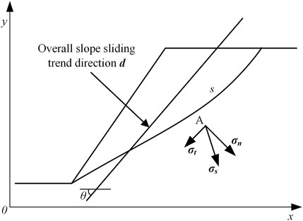
FIGURE 4. Sketch of safety factor solving by vector sum method.
Define the overall slope sliding trend direction d as the vector sum direction of the tangential stress σt of each point on the slip surface. The expression is:
where ds is the micro-segment length of the slip surface.
The anti-sliding force vector of point A is σs’, its tangential component is σt’, and the normal component is σn’:
where dt is the unit vector of tangential anti-sliding force vector direction of point A and σn is the normal stress of the slip surface applied by a sliding body. Since the slope is generally under pressure state, when σn > 0, it indicates that the slip surface is under tensile stress, therefore set σn = 0.
The vector sum method safety factor Fs is defined as the ratio of the algebraic sum of the total anti-sliding force vector projection and the overall sliding force vector in the direction of the overall potential sliding trend of the slope. Therefore, the safety factor Fs is:
where ∫s[σs’(-d)]ds, ∫s(σsd)ds are the algebraic projection sum of the anti-sliding force and the sliding force vector in the direction of the overall potential sliding of the slope, respectively.
The vector sum method can describe the dynamic change characteristics of seismic slope stability, but the overall slope stability cannot be evaluated directly under earthquake action. Therefore, it is necessary to calculate the equivalent safety factor of the slope with other algorithms and evaluate the slope stability.
To directly reflect the impact of the progressive failure process on slope stability, the average safety factor
where n is the total number of discrete points of curves and Fsi is the ith safety factor on the curves.
The instability probability Pf is defined as the ratio of the number of safety factors less than 1 to the total number in the discretization curves, reflecting the uncertainty of slope instability during the earthquake (Falamaki et al., 2021). The expression is as follows:
where m is the number of safety factors less than 1 in the discrete curve.
A seismic slope stability analysis method considering the progressive failure of slip surface is proposed that reflects the stability state of the seismic slope, according to the characteristics that that different states of the rock-soil mass show diverse strength properties. The method combines the strain-softening model, the vibration deterioration model, and the vector sum method. The flowchart is shown in Figure 5. The specific steps are as follows:
1) Establish a numerical model according to slope geometry.
2) Determine the physical and mechanical parameters of the rock-soil mass and the expression of the strain-softening model.
3) Combine these values with the dichotomy strength reduction method, and locate the position of the critical slip surface of the slope according to the maximum shear strain increment.
4) Repeat the static analysis for the numerical model to obtain the initial state before the earthquake.
5) Determine the vibration deterioration model of the failure surface according to the cyclic shear test of the rock mass structural plane.
6) Input the seismic load into the numerical model and select the corresponding ideal elastoplastic, strain-softening, or vibration deterioration constitutive models according to the rock-soil mass state.
7) Based on the vector sum method, calculate the safety factor of the critical sliding body at each step. Obtain the time-history curve of the dynamic safety factor.
8) Calculate the average safety factor and instability probability of the time-history curve to determine the stability state of the seismic slope.
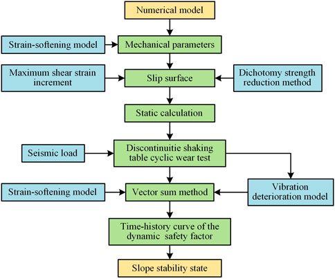
FIGURE 5. Typical workflow of seismic slope stability evaluation method.
The following example will briefly explain the impact of the progressive failure of seismic slope stability. A simplified slope model is adopted in this article to explain the research process because of the large calculation workload of the actual engineering model. However, the method in this article is not limited to this simple model and is still applicable to slopes with multiple strata and structural planes. The numerical model of the slope is established by FLAC3D, as shown in Figure 6. The slope height is 10 m, and the slope angle is about 60°. The numerical slope model is divided into 10,536 units and 22,212 nodes.
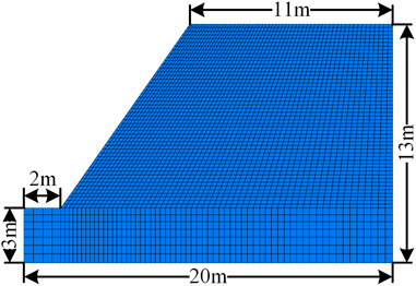
FIGURE 6. Slope numerical model.
The physical and mechanical parameters of the rock-soil mass are shown in Table 1 (Wang et al., 2018). The strength parameters selection process of the numerical unit is shown in Figure 7. All units in the model are searched to obtain their cumulative plastic shear and tensile strains at each step. The unit in the elastic stage obeys the ideal elastoplastic model, and the strength parameters remain the same. When the plastic deformation occurs, the strength parameters are attenuated according to the strain-softening model shown in Figure 3. When partial units reach the ultimate plastic strain, which is the failure stage, many cracks occur in the rock-soil mass, and the bearing capacity of the slope is mainly provided by the lock-up segment and the failure surface strength parameters (Cao et al., 2008). The strength parameter of the cracks becomes the residual strength. Therefore, under the action of earthquakes, the numerical unit strength parameters of the failure stage are further attenuated according to the vibration deterioration model. From the failure of the units to the end of the seismic load, the shear strength parameters of these units at each step are the product of the residual strength and the vibration deterioration coefficient.
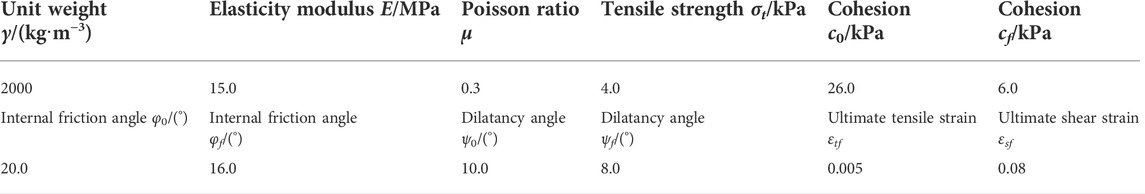
TABLE 1. Mechanical parameters of the rock mass.
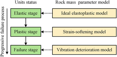
FIGURE 7. Parameters selection of seismic slope numerical units.
Static slope stability is calculated based on the dichotomy strength reduction method, and the static safety factor of the elastoplastic model is 1.26, which coincides with the result of the built-in strength reduction method (1.27). This result shows that the dichotomy strength reduction method is reasonable and reliable. Under the critical state, the slip surface position of the elastoplastic model and strain-softening model obtained by the dichotomy strength reduction model is shown in Figure 8. It can be seen that the calculated critical slip surface of the slope with the strain-softening model is shallower and has less stability than that of the elastoplastic model because the progressive failure characteristics of geotechnical materials are considered.
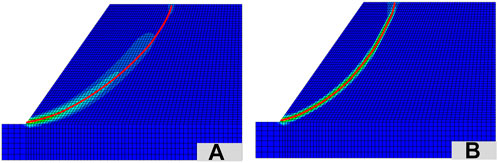
FIGURE 8. Critical slip surface obtained by dichotomy strength reduction method. (A,B) Elastoplastic model (A) and strain-softening model (B).
Based on the aforementioned critical slip surface, the slope safety factors calculated by the three analysis methods are shown in Table 2. The safety factors calculated by the vector sum method and the two strength reduction methods are almost the same, which shows that solving the slope safety factor by the vector sum method is credible.
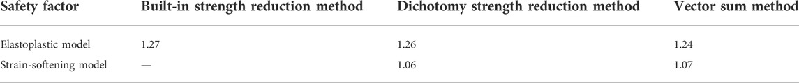
TABLE 2. Safety factors calculated by different methods.
Three models, including elastoplastic, strain-softening, and strain-softening + vibration deterioration, are taken to analyze the numerical slope model and describe the influence of rock-soil mass strength parameter attenuation on slope dynamic stability during a progressive failure. Among them, a simple harmonic vibration wave is used to simulate the seismic load, and acceleration time history is a = λcos(2πft), λ = 1.25 m/s2, which is equivalent to the acceleration amplitude under seismic intensity Ⅶ. The seismic wave frequency f = 2 Hz, and the duration is 5 s. The vertical acceleration amplitude is 1/2 of the horizontal acceleration; the vertical peak acceleration takes 0.63 m/s2 (Ling et al., 1997).
The dynamic stability analysis is based on static analysis. First, based on FLAC3D numerical analysis software, static boundary conditions and physical and mechanical parameters are set in the model, where the initial state before the earthquake is obtained by static analysis. Second, the input dynamic load, dynamic boundary conditions, and damping type are defined. In this article, viscous boundary conditions are used to absorb incident waves on the boundary, and Rayleigh damping is used to make the model converge faster, where the minimum critical damping ratio is set at 0.05, and the center frequency is set at 30 Hz (Itasca 2013). Third, all units in the model are searched to obtain their cumulative plastic shear and tensile strains at each step. The corresponding ideal elastoplastic, strain-softening, or vibration deterioration constitutive models are selected according to Figure 7, based on the rock-soil mass unit state. Then, regarding the critical sliding body obtained from the static analysis as the analysis object and the sliding direction of the unit on the critical slip surface as the direction of shear stress, the potential critical slip surface in Figure 8 is discretized into several units. Finally, the safety factor is calculated by the vector sum method to obtain the time history safety factor curve and stability evaluation results of the seismic slope.
When using the elastoplastic model for calculation under the static condition, the maximum shear strain increment is 0.015, with only local damage in the slope foot, as shown in Figure 9A. Under the action of the dynamic load, according to the critical slip surface shown in Figure 8A, the dynamic response law of the seismic slope is calculated by the vector sum method, as shown in Figures 9B–D. It can be seen that the local damage of the seismic slope extends to the inside, compared to the static conditions, and the maximum shear strain increment increases to 0.061. During the seismic dynamic process, the minimum safety factor is 0.30, and the maximum safety factor is 2.40. The corresponding times are 0.56 and 1.22 s, respectively. After the action of dynamic load, the final safety factor of a seismic slope tends to be 1.19, which is not much different from the factor before the dynamic load.
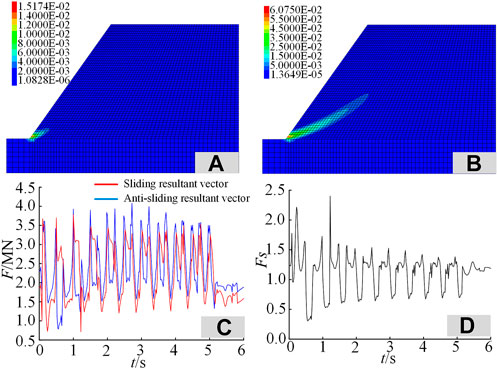
FIGURE 9. Static/dynamic slope response based on the elastoplastic model. (A–D) Maximum shear strain increment in the static state (A), maximum shear strain increment in the dynamic state (B), algebraic sum of the sliding force vector and anti-sliding force vector (C), and dynamic time history safety factor (D).
When using the strain-softening model for calculation, the response law of a seismic slope is shown in Figure 10. After the dynamic calculation, the sliding band formed by the maximum shear strain incremental cloud map is the same as the critical slip surface position of the static state search. Relative to the elastoplastic model, the slope plastic yield surface continues to expand, reaching a maximum shear strain increment of 0.588. The cohesion of some units on the slope slip surface is reduced to 6 kPa, and the internal friction angle is reduced to 16°, causing obvious shear failure of the slip surface. The tensile strength of some units in the foot and the rear edge of the slope is reduced to 0 to reach the ultimate plastic tension strain, causing tension damage. The tension crack of the rear edge of the slope top is formed, following the progressive destruction law of the seismic slope mentioned before. During the seismic dynamic load process, the minimum and maximum safety factors of the slope are 0.29 and 2.52, respectively, and the corresponding times are 0.70 and 0.26 s. After the dynamic load, the final slope safety factor tends to be 1.03, obviously less than the one calculated by the elastoplastic model. The seismic slope tends to the critical failure state.
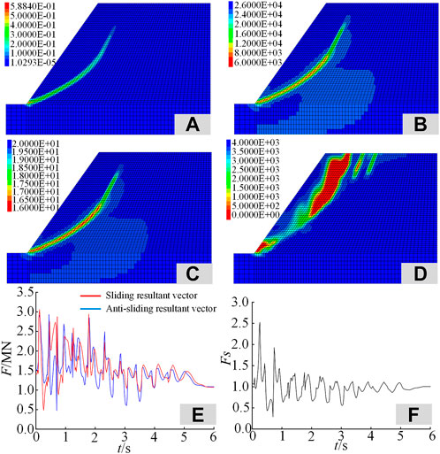
FIGURE 10. Dynamic response of slope based on the strain-softening model. (A–F) Maximum shear strain increment in the dynamic state (A), change of cohesion (B), change of internal friction angle (C), change of tensile strength (D), algebraic sum of the sliding force vector and anti-sliding force vector (E), and dynamic time history safety factor (F).
Based on the strain-softening model, the failure state occurs when the rock-soil mass unit reaches the ultimate plastic strain. Combined with the vibration deterioration model, according to Eq. 7, the strength parameters of the units of the failure stage were reassigned by Fish language. The vibration deterioration coefficient expression is generally obtained through the shaking table cyclic wear test of the rock structure plane. To simplify the analysis process, the vibration deterioration factor D(t) of the failure surface can be replaced by the result of a dynamic load test on the rock structure surface obtained by Ni et al. (2013) under a Ⅶ degree earthquake intensity (λ = 1.25 m/s2). The vibration deterioration factor of the slope failure surface is shown in Figure 11A.
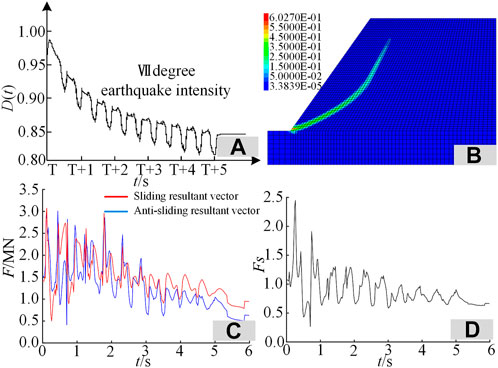
FIGURE 11. Dynamic slope response based on strain-softening + vibration deterioration model. (A–D) Vibration deterioration coefficient (A), maximum shear strain increment in the dynamic state (B), algebraic sum of the sliding force vector and anti-sliding force vector (C), and dynamic time history safety factor (D).
Considering the strain-softening and vibration deterioration characters of the seismic slope at the same time, the dynamic response law of a slope is shown in Figures 11B–D. It is known that the slope shear plastic yield surface is further developed, and the maximum shear strain increment reaches 0.603. During the seismic dynamic load process, vibration deterioration phenomena appear in the strength parameters of the failure surface. According to Eqs 10–12, the attenuation of the shear strength parameter results in the anti-sliding vector σs’ declining. Compared to the sliding force vector ∫s(σsd)ds, the slope anti-slide force vector ∫s[σs’(-d)]ds falls, resulting in the overall slope safety factor dropping. The minimum and the maximum safety factors are 0.27 and 2.45, respectively, and the corresponding times are 0.70 and 0.26 s; the time is consistent with the strain-softening model. The final safety factor tends to be 0.67, indicating that the slope is in a destructive state.
Under the aforementioned three models, the calculated seismic slope stability evaluation indicators are shown in Table 3 according to Eqs 14, 15. Without considering the progressive slope damage, the elastoplastic model is used for numerical calculation, and the average safety factor and the instability probability of the seismic slope are 1.11% and 28.57%, respectively. When considering the progressive failure under the earthquake, the average safety factor of the seismic slope calculated in this method drops significantly to 0.88, the instability probability increases significantly to 73.42%, and the slope becomes unstable. For seismic slope engineering with strict safety grades, a shaking table cyclic wear test should be carried out to determine the model parameters of the failure surface vibration deterioration. Meanwhile, considering the strain-softening and failure surface vibration deterioration characteristics of a rock-soil mass is crucial to truly characterize the stability state of a seismic slope.
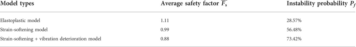
TABLE 3. Stability evaluation index under different models.
In the numerical simulation of slope engineering, a proper constitutive model is crucial for the accurate evaluation of slope stability. However, under different stress-strain states, the mechanical properties of geotechnical materials show significant differences, leading to a unified constitutive model that cannot be adopted to express their mechanical response features under external forces (Cheng and Lau, 2008). The stability of the seismic slope is the result of the joint action of internal and external factors. Under the cyclic shear action of a seismic load, there is both a strain-softening effect in the geotechnical materials in the slope and a wear and passivation phenomenon in the rock mass structure (Ni et al., 2013). Previous studies have ignored the interrelation between rock-soil materials and dynamic load in a seismic slope and have not fully considered the influence of dynamic loading on the strength deterioration of a rock-soil mass in a seismic slope.
According to the failure mechanism of a slope subject to an earthquake, the strain-softening and vibration deterioration models are integrated into the numerical simulation. The corresponding constitutive relation is given based on the state of geotechnical materials, then the stability analysis method of a seismic slope that considers the progressive failure of slip surface is proposed. This method has the following advantages. 1) The strain-softening model and vibration deterioration model are introduced to quantitatively characterize the strength of a rock-soil mass, and a bridge between numerical simulation and material parameter assignment is constructed. These two models describe the features of geotechnical materials at different stages under the action of seismic dynamic loading, which can accurately describe the rock-soil strength variation of a seismic slope. 2) The strain-softening model, vibration deterioration model, and vector sum method are reasonably integrated to obtain the dynamic time-history safety factor of the slope under the action of the earthquake, which can represent the stability state of seismic slopes more comprehensively and reliably. 3) As shown in Figures 10B–D, the proposed method can obtain the contour figure of rock-soil mass strength parameter variation, which can reflect the failure features inside the slope. This result shows the formation process of a slip surface on a slope and is of great value to the research of slope failure mechanism and progressive development process. 4) The effectiveness of the proposed method is further illustrated through an example. If the traditional elastoplastic model is used to calculate the stability of the seismic slope, the strength weakening and progressive failure features in the slope failure process will be ignored, and the calculation results are a little unsafe. Based on the aforementioned analysis, the method in this article can reasonably calculate the safety factor of the seismic slope by considering the internal and external factors of the earthquake and has a good application prospect in accurately evaluating the seismic slope stability.
Although the stability results of the seismic slope calculated by the proposed method are more reasonable and reliable than those of existing studies, there are still some limitations and deficiencies. 1) There are some simplifying assumptions in the calculation. For example, the strain-softening model is simplified into a linear piecewise function, which will lead to certain calculation errors between the calculation results and the actual stability. This is a defect in all slope stability calculation methods. 2) The vibration deterioration model is related to the properties of rock mass structure and dynamic load conditions, and the expression is relatively complex. The vibration deterioration model needs to be further explored by more shaking table cyclic shear tests for a more general mathematical expression. 3) Construction of the strain-softening and vibration deterioration model requires various rock mechanics tests, especially cyclic shear tests. The richer the experiment, the more accurate the constructed model, but the lower the efficiency. Therefore, seeking the balance between accuracy and efficiency of the constructed model will be the focus of the next research stage.
The progressive failure mechanism of a seismic slope can be described according to the characteristics of the action of seismic loads on geotechnical materials. Strain-softening and vibration deterioration models are introduced to characterize the progressive failure process of the plasticity failure stage, which can accurately describe the attenuation of the rock-soil strength of a seismic slope.
The strain-softening and vibration deterioration models are embedded in the seismic slope stability calculation and allow for selecting an appropriate rock-soil mass constitutive model according to the stress-strain state of the slope. A seismic slope stability analysis method that considers progressive failure and is combined with the vector sum method is formed using the dichotomy strength reduction method to locate the position of the critical slip surface of the slope and then calculate the dynamic time history safety factor. The proposed method can represent the stability state of seismic slopes more comprehensively and reliably than existing methods.
This method is used to analyze the dynamic stability of the calculation examples. The seismic slope produces shear and tension failure, which verifies the progressive failure evolution of the slip surface of the seismic slope. The comparative analysis of the safety factor in the three models shows that the calculation results using the traditional elastoplastic model are unsafe, which verifies the necessity and rationality of considering strain-softening and vibration deterioration when analyzing the dynamic stability of a seismic slope.
The original contributions presented in the study are included in the article/Supplementary Material. Further inquiries can be directed to the corresponding author.
Conceptualization, ZA; investigation, HZ; writing—original draft preparation, HZ and QY; writing—review and editing, ZA, CJ, and ZR; supervision, SW; and funding, SW. All authors listed have made a substantial, direct, and intellectual contribution to the work and approved it for publication.
Funding for this work was supported by the National Key Research and Development Funding Projects of China (Grant No. 2017YFC0805303) and the Yunnan Innovation Team (Grant No. 202105AE160023).
ZA, CJ, and QY were employed by Power China Road Bridge Group Co. Ltd.
The remaining authors declare that the research was conducted in the absence of any commercial or financial relationships that could be construed as a potential conflict of interest.
All claims expressed in this article are solely those of the authors and do not necessarily represent those of their affiliated organizations, or those of the publisher, the editors, and the reviewers. Any product that may be evaluated in this article, or claim that may be made by its manufacturer, is not guaranteed or endorsed by the publisher.
Alfaro, P., Delgado, J., García-Tortosa, F., Giner, J., Lenti, L., López-Casado, C., et al. (2012). The role of near-field interaction between seismic waves and slope on the triggering of a rockslide at Lorca. Nat. Hazard Earth Sys. 12, 3631–3643. doi:10.5194/nhess-12-3631−2012
Baker, R., Shukha, R., Operstein, V., and Frydman, S. (2006). Stability charts for pseudo-static slope stability analysis. Soil Dyn. Earthq. Eng. 26, 813–823. doi:10.1016/j.soildyn.2006.01.023
Bolla, A., and Paronuzzi, P. (2021). Seismic analysis of a limestone rock slope through numerical modelling: Pseudo-static vs. non-linear dynamic approach. In IOP Conference Series: Earth and Environmental Science 906, 012093.
Cao, W. G., Zhao, H., Zhang, L., and Zhang, Y. J. (2008). Dynamic stability softening constitutive model for rock considering effect of damage threshold and its parameters determination method. Chin. J. Rock Mech. Eng. 6, 1148.
Che, A., Yang, H., Wang, B., and Ge, X. (2016). Wave propagations through jointed rock masses and their effects on the stability of slopes. Eng. Geol. 201, 45–56. doi:10.1016/j.enggeo.2015.12.018
Cheng, Y. M., and Lau, C. K. (2008). Slope stability analysis and stabilization: New methods and insight. London: CRC Press.
Crawford, A. W., and Curran, J. H. (1982). The influence of rate and displacement dependent shear resistance on the response of rock slopes to seismic loads. Int. J. Rock Mech. Min. Sci. Geomechanics Abstr. 19, 1–8. doi:10.1016/0148-9062(82)90704-5
Di, B., Stamatopoulos, C. A., Dandoulaki, M., Stavrogiannopoulou, E., Zhang, M., and Bampina, P. (2017). A method predicting the earthquake-induced landslide risk by back analyses of past landslides and its application in the region of the Wenchuan 12/5/2008 earthquake. Nat. hazards 85, 903–927. doi:10.1007/s11069-016-2611-7
Du, Y., Li, H., Chicas, S. D., and Huo, L. (2022). Progress and perspectives of geotechnical anchor bolts on slope engineering in China. Front. Environ. Sci. 10, 928064. doi:10.3389/fenvs.2022.928064
Du, Y., Xie, M., and Jia, J. (2020). Stepped settlement: A possible mechanism for translational landslides. Catena 187, 104365. doi:10.1016/j.catena.2019.104365
Eberhardt, E., Stead, D., and Coggan, J. S. (2004). Numerical analysis of initiation and progressive failure in natural rock slopes—The 1991 randa rockslide. Int. J. Rock Mech. Min. Sci. (1997). 41, 69–87. doi:10.1016/S1365-1609(03)00076-5
Falamaki, A., Shafiee, A., and Shafiee, A. H. (2021). Under and post-construction probabilistic static and seismic slope stability analysis of Barmshour Landfill, Shiraz City, Iran. Bull. Eng. Geol. Environ. 80, 5451–5465. doi:10.1007/s10064-021-02277-4
Fan, X., Qiang, X., Scaringi, G., Dai, L., Li, W., Dong, X., et al. (2017). Failure mechanism and kinematics of the deadly june 24th 2017 Xinmo landslide, maoxian, Sichuan, China. Landslides 14, 2129–2146. doi:10.1007/s10346-017-0907-7
Ge, X. R. (2008). Deformation control law of rock fatigue failure, real-time X-ray CT scan of geotechnical testing, and new method of stability analysis of slopes and dam foundations. Chin. J. Geotech. Eng. 1, 1.
Guo, M., Ge, X., and Wang, S. (2011). Slope stability analysis under seismic load by vector sum analysis method. J. Rock Mech. Geotechnical Eng. 3, 282–288. doi:10.3724/SP.J.1235.2011.00282
Jafari, M. K., Pellet, F., Boulon, M., and Hosseini, K. A. (2004). Experimental study of mechanical behaviour of rock joints under cyclic loading. Rock Mech. Rock Eng. 37, 3–23. doi:10.1007/s00603-003-0001-4
Karray, M., Hussien, M. N., Delisle, M. C., and Ledoux, C. (2018). Framework to assess pseudo-static approach for seismic stability of clayey slopes. Can. Geotech. J. 55, 1860–1876. doi:10.1139/cgj-2017-0383
Koo, R. C., Kwan, J. S., and Sze, E. H. (2016). Stability assessment of soil slopes subject to blasting vibrations based on time history analyses. HKIE Trans. 23, 130–137. doi:10.1080/1023697X.2016.1201438
Lee, H. S., Park, Y. J., Cho, T. F., and You, K. H. (2001). Influence of asperity degradation on the mechanical behavior of rough rock joints under cyclic shear loading. Int. J. Rock Mech. Min. Sci. (1997). 38, 967–980. doi:10.1016/S1365-1609(01)00060-0
Li, Y., Wu, W., and Liu, B. (2019). Predicting the shear characteristics of rock joints with asperity degradation and debris backfilling under cyclic loading conditions. Int. J. Rock Mech. Min. Sci. (1997). 120, 108–118. doi:10.1016/j.ijrmms.2019.06.001
Ling, H. I., Leshchinsky, D., and Mohri, Y. (1997). Soil slopes under combined horizontal and vertical seismic accelerations. Earthq. Eng. Struct. Dyn. 26, 1231–1241. doi:10.1002/(sici)1096-9845(199712)26:12<1231::aid-eqe707>3.0.co;2-z
Ma, Z. Y., Liao, H. J., Dang, F. N., and Cheng, Y. X. (2021). Seismic slope stability and failure process analysis using explicit finite element method. Bull. Eng. Geol. Environ. 80, 1287–1301. doi:10.1007/s10064-020-01989-3
Macedo, J., and Candia, G. (2020). Performance-based assessment of the seismic pseudo-static coefficient used in slope stability analysis. Soil Dyn. Earthq. Eng. 133, 106109. doi:10.1016/j.soildyn.2020.106109
Negi, P., Chakraborty, T., and Bhalla, S. (2022). Viability of electro-mechanical impedance technique for monitoring damage in rocks under cyclic loading. Acta Geotech. 17, 483–495. doi:10.1007/s11440-021-01181-1
Ni, W. D., Tang, H. M., Liu, X., and Wu, Y. P. (2013). Dynamic stability analysis of rock slope considering vibration deterioration of structural planes under seismic loading. Chin. J. Rock Mech. Eng. 32, 492.
Pang, R., Xu, B., Zhou, Y., and Song, L. (2021). Seismic time-history response and system reliability analysis of slopes considering uncertainty of multi-parameters and earthquake excitations. Comput. Geotech. 136, 104245. doi:10.1016/j.compgeo.2021.104245
Quinn, P. E., Diederichs, M. S., Rowe, R. K., and Hutchinson, D. J. (2012). Development of progressive failure in sensitive clay slopes. Can. Geotech. J. 49, 782–795. doi:10.1139/t2012-034
Shinoda, M., Watanabe, K., Sanagawa, T., Abe, K., Nakamura, H., Kawai, T., et al. (2015). Dynamic behavior of slope models with various slope inclinations. Soils Found. 55, 127–142. doi:10.1016/j.sandf.2014.12.010
Song, D., Chen, Z., Ke, Y., and Nie, W. (2020). Seismic response analysis of a bedding rock slope based on the time-frequency joint analysis method: A case study from the middle reach of the jinsha river, China. Eng. Geol. 274, 105731. doi:10.1016/j.enggeo.2020.105731
STCM Science and Technology Committee of the Ministry of Aviation Industry (1990). Manual of stress concentration factors. Beijing: Higher Education Press.
Valentin, G., Giona, P., and Erik, E. (2016). Numerical investigation of seismically induced rock mass fatigue as a mechanism contributing to the progressive failure of deep-seated landslides. Rock Mech. Rock Eng. 49, 2457–2478. doi:10.1007/s00603-015-0821-z
Wang, J., Yao, L., and Hussain, A. (2010). Analysis of earthquake-triggered failure mechanisms of slopes and sliding surfaces. J. Mt. Sci. 7, 282–290. doi:10.1007/s11629-010-2020-4
Wang, L., Zhang, X., and Tinti, S. (2021). Large deformation dynamic analysis of progressive failure in layered clayey slopes under seismic loading using the particle finite element method. Acta Geotech. 16, 2435–2448. doi:10.1007/s11440-021-01142-8
Wang, S. J., and Zhang, J. M. (1982). Dynamic analysis of sliding stability of slope rock mass. Sci. Geol. Sin. 2, 162.
Wang, W., Chen, G. Q., Zhu, J., and Huang, R. Q. (2018). Slope stability calculated with strength reduction method considering tensile and shear progressive failure. Chin. J. Rock Mech. Eng. 37, 2064.
Wang, Y., Wu, S. X., Zhou, J. K., and Shen, D. J. (2010). Experimental study of dynamic axial tensile mechanical properties of granite. Chin. J. Rock Mech. Eng. 29, 2328.
Xu, C., and Xu, X. (2013). Controlling parameter analyses and hazard mapping for earthquake-triggered landslides: An example from a square region in beichuan county, sichuan province, China. Arab. J. Geosci. 6, 3827–3839. doi:10.1007/s12517-012-0646-y
Yang, Y., Wu, W., and Zheng, H. (2021). Stability analysis of slopes using the vector sum numerical manifold method. Bull. Eng. Geol. Environ. 80, 345–352. doi:10.1007/s10064-020-01903-x
Yu, G., Bu, L., Wang, C., and Farooq, A. (2022). Composition analysis and distributed assumption GIS model of normal stress on the slope sliding surface. Front. Earth Sci. 10, 923620. doi:10.3389/feart.2022.923620
Zhang, B., Jiang, Y., Cheng, H., and Liu, Z. (2021). Upper bound analysis of the stability of 3D slopes in the saturated soft clay subjected to seismic effect. Front. Earth Sci. 9, 785854. doi:10.3389/feart.2021.795854
Zhang, K., Cao, P., and Bao, R. (2013). Progressive failure analysis of slope with strain-softening behaviour based on strength reduction method. J. Zhejiang Univ. Sci. A 14, 101–109. doi:10.1631/jzus.A1200121
Zhao, L., Jiao, K., Zuo, S., Yu, C., and Tang, G. (2020). Pseudo-static stability analysis of wedges based on the nonlinear Barton-Bandis failure criterion. Geomech. Eng. 20, 287–297. doi:10.12989/gae.2020.20.4.287
Keywords: slope engineering, earthquake, progressive failure, strain-softening, vibration deterioration
Citation: Ai Z, Zhang H, Wu S, Jiang C, Yan Q and Ren Z (2022) Study on the slope dynamic stability considering the progressive failure of the slip surface under earthquake. Front. Earth Sci. 10:981503. doi: 10.3389/feart.2022.981503
Received: 29 June 2022; Accepted: 19 August 2022;
Published: 15 September 2022.
Edited by:
Yan Du, University of Science and Technology Beijing, ChinaReviewed by:
Fei Guo, China Three Gorges University, ChinaCopyright © 2022 Ai, Zhang, Wu, Jiang, Yan and Ren. This is an open-access article distributed under the terms of the Creative Commons Attribution License (CC BY). The use, distribution or reproduction in other forums is permitted, provided the original author(s) and the copyright owner(s) are credited and that the original publication in this journal is cited, in accordance with accepted academic practice. No use, distribution or reproduction is permitted which does not comply with these terms.
*Correspondence: Huajin Zhang, aHVhamluemhhbmcxMDAxQDE2My5jb20=
Disclaimer: All claims expressed in this article are solely those of the authors and do not necessarily represent those of their affiliated organizations, or those of the publisher, the editors and the reviewers. Any product that may be evaluated in this article or claim that may be made by its manufacturer is not guaranteed or endorsed by the publisher.
Research integrity at Frontiers
Learn more about the work of our research integrity team to safeguard the quality of each article we publish.