 Wuqun Li
 Weijian Mao
 Quan Liang
- Research Center for Computational and Exploration Geophysics, State Key Laboratory of Geodesy and Earth’s Dynamics, Innovation Academy for Precision Measurement Science and Technology, Chinese Academy of Science, Wuhan, China
The vertical seismic profiling (VSP) acquisition technique deploys sensors down a borehole, which often goes deep into the target area. It is easy to produce serious “smile” migration artifacts near the sensors during the migration imaging process of VSP data, which contaminates the imaging profile and affects the subsequent geological interpretation. In this paper, we analyze in detail the formation of these migration artifacts during the migration of VSP data. We extend the generalized Radon transform (GRT) migration method to the dip-angle domain and then generate dip-angle domain common image gathers (DDCIGs). Meanwhile, a variant sigmoid weighting function is applied to the DDCIGs to suppress the migration artifacts. The numerical results of synthetic and field data demonstrate high-quality DDCIG images and the significant artifact suppression capability of the proposed method.
Introduction
Imaging seismic data through migration is a reliable and necessary step to understanding the subsurface structure in modern seismic exploration. The seismic data are, in a sense, both limited and redundant. The data, whether recorded from land or sea, are always within a certain range along the exploration line, that is, migration summation always has a natural truncated boundary due to the acquisition limitation. Hence, Kirchhoff-type (i.e., ray-based migration) is often called limited aperture migration (LAM) (Sun, 1998). Moreover, even the limited migration aperture might be further restricted in the practical migration process. Seismic data are acquired under the principle of redundancy to suppress interference and enhance the reflection events. However, this principle does not apply to limited-aperture acquisition, such as boreholes, tunnels, or mines (Lüth et al., 2005). In such a case, the redundant data or boundary data will cause migration noise and extra computation.
Therefore, from both the aperture limitation and redundancy point of view, the aperture needs to be considered in the migration process. The width of the migration aperture is one of the critical parameters in the standard ray-based migration (Yilmaz, 2001). An appropriate migration aperture is important to suppressing migration artifacts and reducing cost. Safar (1985) studied the effects of migration aperture on lateral resolution and migration noise when carrying out diffractor point imaging by the Kirchhoff summation scheme. Yilmaz (1987) showed that both the excessively large and the excessively small migration apertures lead to poor imaging quality. Schleicher et al. (1997) obtained the relationship between the (projected) Fresnel zone and the minimum migration aperture. He also points out that there is still an unsolved problem to determine the tangency point where the minimum aperture is to be centered. Sun (1998) provided the theoretical framework for the design of the migration aperture through LAM. He also showed that the migration aperture should be at least as large as the first Fresnel zone of the stationary point. Sun and Bancroft (2001) went further to conclude that the minimum pre-stack migration aperture should be twice the size of the Fresnel zone. Hertweck et al. (2003) related the migration aperture to the maximum migration dip. They demonstrated that a taper region of the size of the second projected Fresnel zone should be added to the migration operator. Nevertheless, it is difficult to determine the exact center and size of the Fresnel zone, and thus, the optimal migration aperture for each depth point. A compromise between accuracy and practicality is to fix an aperture or a maximum migration dip. It is important to realize the relationship between aperture and maximum dip to image (Robein, 2010). Also, imaging higher-order scattering can increase illumination and reduce migration artifacts (Zuberi and Alkhalifah, 2013; Zuberi and Alkhalifah, 2014).
The migrated dip-angle domain has properties that are favorable for addressing both issues; the aperture position and its width (Klokov and Fomel, 2013). In the dip-angle domain, a refection event has a concaved shape with an apex whose position corresponds to the reflector dip (Landa et al., 2008; Klokov and Fomel, 2012). The effective imaging range or Fresnel zone is concentrated in the vicinity of the apex position. Aperture restriction can be achieved by applying a taper weight function to the event. Klokov and Fomel (2013) defined a weighting function by estimating the consistency of the constant-dip-angle partial images to smoothly attenuate the destructive events away from the apexes. This method can reduce migration noise while preserving diffraction energy. Xue and Liu (2018) proposed a multidirectional wavefield decomposition Reverse Time Migration (RTM) method to suppress the low-frequency noise and migration artifacts. The full wavefields are separated into eight sub-wavefields according to the propagation direction of the wavefronts excited by the source and receiver, respectively. This wave-based migration method is essentially similar to the dip-angle domain ray-based migration and the problem of angle estimation is prominent when wavefields are complicated in shape and wavefronts overlap. Recently, Wu et al. (2022) used the U-Net neural network to automatically identify Fresnel zones in the dip-angle domain. However, there are still challenges when encountering data with a low signal-to-noise ratio and structure complexity.
In surface seismic profile (SSP) exploration, the migration artifacts are mainly presented in the form of boundary effects. These diffraction noise effects are sometimes drastically attenuated and not that imperative under a considerably high CDP fold. Compared with SSP data, the noise suppression of the vertical seismic profiling (VSP) profile seems to be more critical. The aperture width for VSP data often is inadequate to obtain a migrated section without much smearing (Yilmaz, 2001). The imaging of VSP data suffers more severe migration artifacts due to a smaller acquisition aperture and more uneven fold than that of SSP data. Furthermore, VSP receivers are deployed deep into the target area, which aggravates the contamination of the section around the well trajectory. Yu and Hornby (2008) implemented a local beam migration scheme to attenuate migration artifacts caused by limited acquisition aperture in VSP data. Lou et al. (2009) attenuated migration smiles and artifacts of VSP images by defining and selecting an appropriate migration aperture angle. Zhou et al. (2010) used a local-angle-domain correlation imaging condition to attenuate migration artifacts. Lou and Simpson (2019) presented an efficient and effective dip filter consistent with the local velocity model in VSP migration, which preserves true dip structures, and in the meantime suppresses migration artifacts. In general, there are relatively few studies on denoising of VSP imaging, which is mainly achieved by limiting the migration aperture. Some wave-based imaging methods are unstable to determine the wavefront propagation direction, and some rely on the prior information of underground structures. Further studies are needed to improve VSP imaging, especially in the application of real data.
In this paper, we develop an imaging method for VSP data based on the weighted dip-domain generalized radon transform (DDGRT) migration. A variant sigmoid weighting function is applied to the dip-angle domain common image gathers (DDCIGs) to suppress the migration noise. We first provide a brief review of the acoustic GRT migration method and extend it to weighted DDGRT. We consider two VSP synthetic datasets generated from a layer model and also a graben model to illustrate the migration noises and validate the effectiveness of noise suppression by the proposed method. A walkaway field data is also used to verify the effectiveness. Numerical experiments and a field data application demonstrate that the proposed approach can effectively suppress migration artifacts and improve imaging results.
Methodology
Weighted dip-angle domain generalized radon transform
We begin with a brief review of the GRT migration or inversion in solving the seismic inverse scattering problem. The Seismic wave propagation in a non-homogeneous fluid medium satisfies the following scalar time-domain wave equation
where compressibility
The functions
where
The linearized integral equation relates the scattered wavefield to the subsurface medium parameters under the Born approximation. The asymptotic solutions of the integral equation have been derived using the inversion theory of the GRT (Beylkin, 1985; Miller et al., 1987; Ouyang et al., 2015). For an arbitrary observation system, the GRT inverse operator on a scattered field at imaging point
and
where
According to Beylkin’s work (Beylkin and Burridge, 1990), the inversion of the generalized Radon transform is derived from a Fourier transform. By adding a layer of integral of the scattering angle to the perturbation parameter in the transformation process, the GRT inversion or migration formula of the scattering-angle domain is obtained (Li et al., 2018; Li et al., 2022).
In this formulation, the Dirac function
where
where
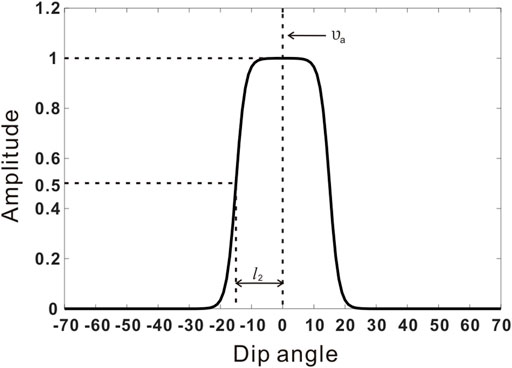
FIGURE 1. The schematic of the variant sigmoid weighting function.
The variant sigmoid weighting function is symmetric about the vertical line
Applying the weighting function to the DDCIGs, we get the eventual weighed dip-angle domain GRT migration formula which helps to suppress the ineffective dip component and produce a denoised migration imaging profile.
Migration noises analysis of VSP imaging
The migration noises are generally caused by the limitation or truncation of data acquisition. The migration trails of the boundary shots often remain on the final imaging profile and form noises. In general, these boundary effect events (BE) can not be enhanced or attenuated by interference in the migration of conventional SSP data. However, in the imaging of VSP data, these boundary effect events are enhanced by constructive interference due to the peculiarity of acquisition and irregular summation resulting in strong migration artifacts near the well trajectory. These artifacts around the well trajectory aggravate the contamination of the seismic profile. Note that migration noises mentioned here do not include acquisition noises like multiples, etc.
We illustrate the migration noises through a single-shot migration process. Figure 2A illustrates an SSP migration process of single-shot gather data generated in a two-layer homogeneous model. The black star denotes the shot position and the inverted triangles denote the positions of the receivers. Since the long axis of the isochronal ellipse is on the same horizontal line, the migration process of the SSP migration is performed by relatively regular superposition. The migration noises are mainly caused by the BE noises. The BE noise is not enhanced because it is at the boundary of the interference region and shows relatively weak amplitude near the acquisition edges after the multi-channel summation. Figure 2B illustrates a VSP migration process of single-shot gather data using the same model. In the case of VSP migration, the long axis of the isochronal ellipse is no longer on the same horizontal line but goes into the subsurface with a certain dip angle due to the varying depth of the ellipse focus (receiver position). Besides the BE noises, the migration artifacts are also produced due to constructive interference. After a multi-channel stack, the migration artifacts are further enhanced to contaminate the migration profile near the well trajectory.
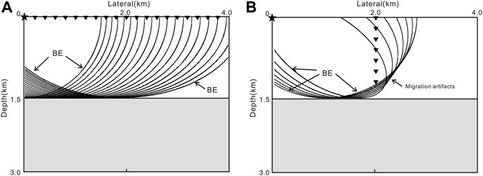
FIGURE 2. Schematic of the migration noise for (A) SSP data and (B) VSP data.
Numerical examples
Imaging of layered model
We begin with a simple horizontal layered model data to further illustrate the migration noises and apply the DDGRT method to it. The model shown in Figure 3A consists of five layers where the velocity is homogeneous in each layer. The model dimensions here are 4.0 km in the horizontal and 3.6 km in the depth directions. The complete acquisition contains 201 sources deployed along the surface and a vertical well located at x = 2000 m with 361 receivers placed along with it. The shot and receiver spacings are 20 and 10 m, respectively. Synthetic data are generated using a finite-difference acoustic modeling program (Thorbecke and Draganov, 2011). The source signature is chosen to be a Ricker wavelet with a maximum frequency of 30 Hz. The recording time is 6 s with a sampling interval of 2 ms.
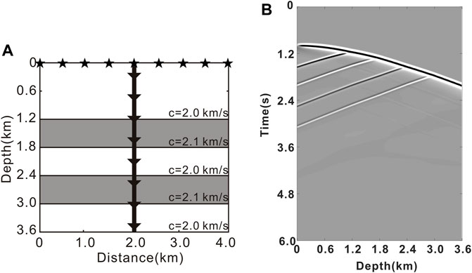
FIGURE 3. (A) The horizontal layered model overlaid with the VSP acquisition geometry. (B) A shot record generated at shot position x = 0 m.
A single shot record is shown in Figure 3B at the shot position x = 0 m. We take the first trace of the record as the input. The profile shown in Figure 4A illustrates the initial migration trajectory which forms the boundary effect noises from the starting trace (white arrows by BE-1). Figure 4B shows the imaging result of the whole channels of this shot. Besides the BE-1 noises, the boundary effect noises (white arrows by BE-2) from the ending trace are also produced and dragged as the depth of the receiver increases. Notably, the amplitude of the BE-2 noise is weaker than that of BE-1 noise since destructive attenuation occurs in the interference region. In addition, migration artifacts marked in the white dotted box, disguised as relatively high-dip angle events are generated. These strong noises, are essentially caused by the coherent interference of boundary effect noises near the well trajectory and become the dominant noises in the VSP imaging profile. Figures 4C,D show the consistent imaging results of shot position x = 4,000 m.
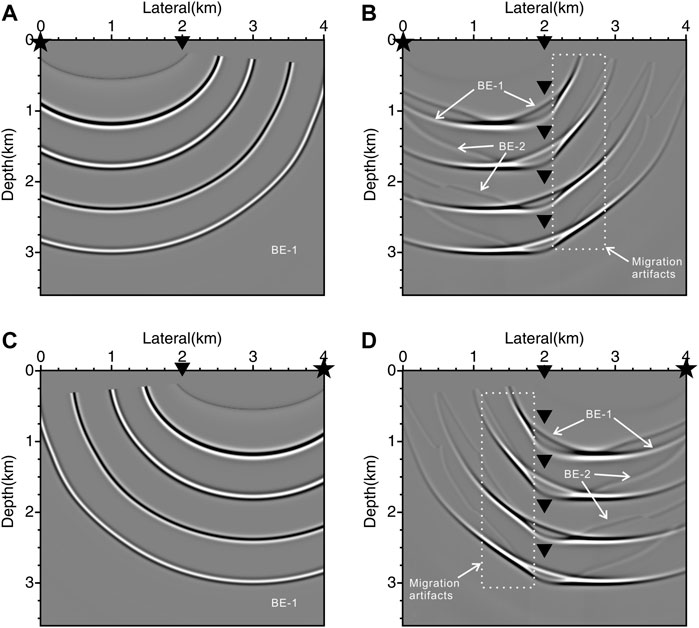
FIGURE 4. The imaging results using (A) the starting trace and (B) the total traces of the shot at position x = 0 m; (C,D) are corresponding imaging results at position x = 4,000 m.
Figure 5A, the summation of Figures 4B,D, illustrates the imaging result of the two shots on the boundary of the acquisition. Figure 5B shows the conventional GRT migration imaging result using the all shot data. As we can see, the noises and artifacts produced by the boundary shot data constitute the major component of the VSP migration noises. Although BE noises are greatly reduced after the summation of total shot data, the amplitude of high-dip migration artifacts is still very strong; almost like that of the reconstructed reflectors. Figure 5C shows the denoised result produced by the summation of the DDCIGs along the dip-angle direction based on weighted DDGRT. Figures 5D,E,F are the enlarged views of the white dotted boxes, respectively. As we can see, the migration artifacts with high-dip angles have been removed by the proposed method.
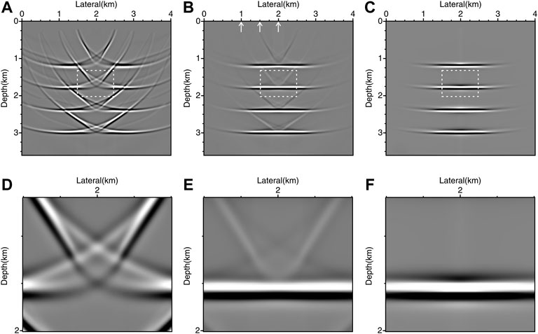
FIGURE 5. The imaging results using (A) two boundary shots by conventional GRT, (B) total shots by conventional GRT, and (C) total shots by weighted DDGRT. (D–F) are the enlarged views of the corresponding area marked by the white dotted boxes.
Based on Eq. 7, we further use the DDGRT method to output CIGs to observe the characteristics of migration artifacts in the dip-angle domain. Figures 6A–C display the initial DDCIGs for the three traces (white arrows in Figure 5B) corresponding to the lateral distances at 1,000, 1,500, and 2000 m, respectively. From the DDCIGs of the three traces, the lateral positions of the concave shape apices are around zero degrees, which corresponds to the local dip of the four horizontal reflectors. At the same time, we can also see that irrelevant noises (marked by white arrows) occur in the high-dip regions away from the concave shape apices, which makes the dip-angle domain favorable for suppressing migration noises. Figures 6D,E,F are the DDCIGs produced by weighted DDGRT for the same traces. The weighted DDGRT removes the high-dip irrelevant events and retains the constructive reflection events centered around the apices.
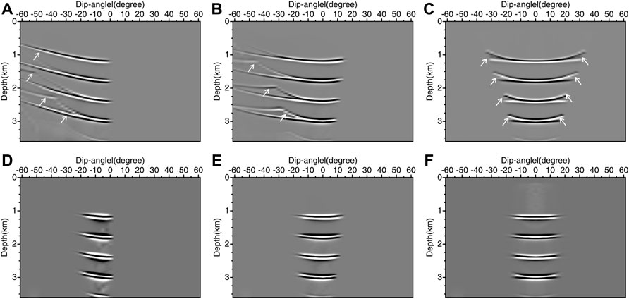
FIGURE 6. The DDCIGs of the layer model data produced by DDGRT at the lateral position of (A) x = 1,000 m, (B) x = 1,500 m, and (C) x = 2000 m. (D–F) are the DDCIGs produced by weighted DDGRT at the same lateral position.
Imaging of a graben model
We use slightly more complex graben model data to verify the validity of the proposed DDGRT method. The model size is 4.0 km × 3.6 km, as shown in Figure 7A, with a lateral and vertical spacing of 10 m. It consists of six homogeneous areas simulating the horizontal, sloping, and undulating structures of the subsurface with embedded graben. A total of 201 sources are deployed along the surface with 20 m shot spacing (red star). The vertical well (white line) is located horizontally at x = 2000 m. An array of receivers is placed along the well trajectory from 0 to 3,600 m with 10 m receiver spacing. The data are synthesized using a Ricker wavelet with a maximum frequency of 30 Hz. The recorded length is 6 s with a time sampling interval of 2 ms. We chose the same acquisition geometry and finite-difference modeling code to generate the synthetic data. Figure 7B presents the imaging results using conventional GRT migration, which effectively images the area around the well trajectory. Nevertheless, considerable artifacts are produced on both sides. Figure 7C shows the imaging result using weighted DDGRT migration. The new approach suppresses the artifacts around the well trajectory and presents a clearer imaging result. Figures 8A–C show the initial DDCIGs for the three traces (white arrows in Figure 7B) corresponding to the lateral distances at 500, 1,300, and 2000 m, respectively. Figures 8D,E,F) are the weighted versions for the same traces. The weighted DDGRT preserves the effective contributions near the concave shape apices and eliminates other irrelevant events (marked by white arrows).
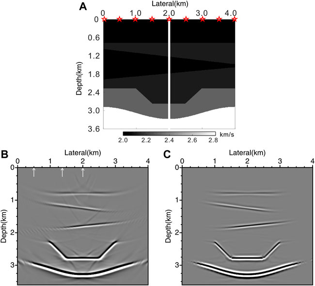
FIGURE 7. The imaging results of the 2D graben model. (A–C) are the velocity model, the imaging results using conventional GRT migration, and weighted DDGRT migration, respectively.
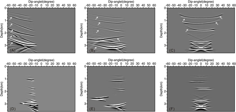
FIGURE 8. The DDCIGs of the graben model data produced by DDGRT at the lateral position of (A) x = 510 m, (B) x = 1,300 m, and (C) x = 2000 m. (D–F) are the DDCIGs produced by weighted DDGRT at the same lateral position.
Field data application
We apply the proposed method to walkway VSP field data. It is a single-component downhole geophones dataset collected by CNPC in Jilin province, northeast China. Figure 9A shows the top view of the acquisition geometry after coordinate rotation. A total of 401 shots (blue circles) are excited at the surface with an average spacing of 20 m and 156 geophones are deployed in the well (red star) with an average spacing of 20 m. An initial velocity field is built along the survey line shown in Figure 9B. The white vertical line represents the location of the geophone array which starts from 660 to 3,760 m in the depth direction. The data are sampled at 1 ms with a length of 6 s. Figures 10A,B show a typical common receiver record and a common shot record of the field VSP data. The record shows that the upgoing reflections are developed with a desirable signal-to-noise ratio.
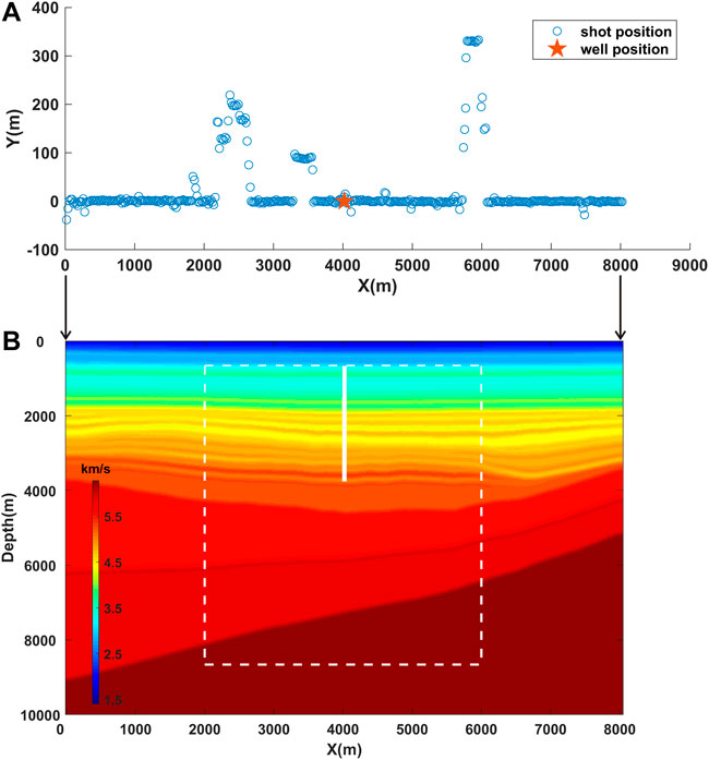
FIGURE 9. (A) The top view of the real data acquisition geometry. (B) The velocity field.
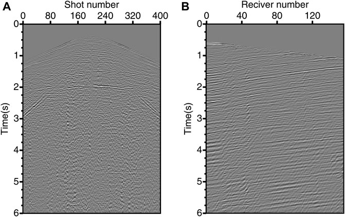
FIGURE 10. (A) The common receiver record. (B) The common shot record.
Figures 11A,B show imaging results of the field data using conventional GRT migration and weighted DDGRT migration. It can be seen that the “smile” migration noises are serious in the profile obtained using conventional GRT migration. The weighted DDGRT migration method suppresses the migration noises and improved the imaging quality of the profile. Figure 12 shows the comparison of the enlarged views of corresponding areas marked by white dotted boxes in Figure 11. The weighted DDGRT removes most of the “smile” migration noises (marked by white arrows). It is worth mentioning that the proposed method yields better results in areas where conventional imaging is discontinuous due to the noises (marked by dotted ellipses).
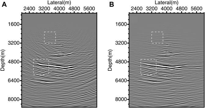
FIGURE 11. The imaging results of the field data using (A) conventional GRT migration and (B) weighted DDGRT migration.
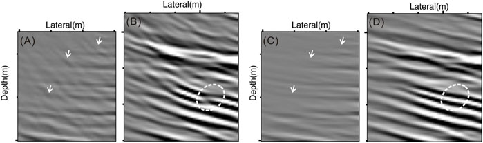
FIGURE 12. Comparison of the enlarged views of corresponding areas marked by white dotted boxes in Figure 11. (A,B) are imaging results of conventional GRT migration; (C,D) are that of weighted DDGRT migration.
Discussion
In this paper, we introduce a variant sigmoid weighting function to the dip-angle domain GRT migration, which enables the method to effectively suppress the migration artifacts in VSP imaging. This function acts like a bandpass filter that passes dip angles within a significant range and rejects ones outside that range. In seismic migration imaging, such as the decomposition of multi-component wave fields, the separation of diffraction and reflection, and the design of migration aperture will be involved in this problem. In the migration aperture design, a rough approach is to choose a stack range around the dip angle of the image point and cut it off to zero outside that range. While this operation will lead to uneven superposition and easy to produce new truncation noise. Another common practice is using a cosine function that weights the attenuation based on the difference between the migration dip of the ray pair and the stratigraphic dip of the image point or reflector. The suppression effect of this method is usually not obvious. Even when the difference between the two angles is large, the imaging results will still have residual artifacts. The proposed weighting function in the manuscript is obtained by shifting and scaling the sigmoid function which is used as an activation function in neural networks. Compared with the cosine function, it has a stronger suppressing effect outside the amplitude preserving region (control by amplitude-preserved width factor). Meanwhile, it helps alleviate the truncation effect.
We use a simple model data to illustrate the noise suppression effect between the cosine function and the variant sigmoid function. Figure 13A shows the homogeneous velocity model with an embedded tilted linear perturbation and the VSP acquisition configuration. The model dimensions here are 3.0 km in lateral and 3.0 km in depth directions. The VSP acquisition contains a vertical well located at the left boundary with 101 receivers (black solid inverted triangle) placed along with it. Five shots (black solid star) are deployed on the surface starting at the left with a spacing of 600 m. Figure 13 shows the imaging results of the five shots. Figure 13B is the imaging result without using the weighting function. Figures 13C,D are imaging results using cosine function and variant sigmoid function, respectively. It can be seen that the migration artifacts (white arrows) developed in the profile without using weighting function. The migration method with the cosine function does not suppress the artifacts near the reflector very well. While the sigmoid function does a good job of suppressing these artifacts without affecting the valid signal. The cosine function can suppress the high steep migration artifacts, but the suppression effect is limited. This issue is particularly obvious in VSP acquisition due to the limitation of the migration aperture. The proposed variant sigmoid function performs significantly better and has an improved suppressing effect.
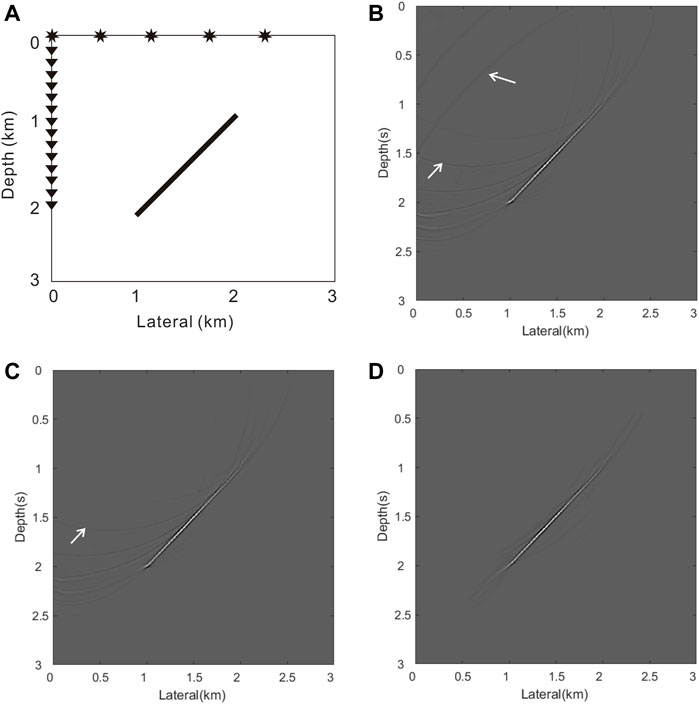
FIGURE 13. Comparison of imaging results between two weighting functions. (A) Homogeneous model and VSP acquisition; (B) Imaging result without weighting function; (C) Imaging results using cosine function; (D) Imaging result using the variant sigmoid function.
The proposed method is essentially an optimization or improvement of the migration imaging method, aiming at the problem of “smile” migration artifacts near the well in VSP. Its applicability conditions are consistent with the migration method. The key lies in the need for a reliable velocity model. Based on this model, the ray-based migration method can generally recover the subsurface structure, and then obtain relatively reliable local dip-angle information of the reflector. Under this premise, the proposed method can be effectively applied. In some cases, especially for the real data with little horizontal variation, we can obtain significant results even set the local dip angle to zero. As mentioned above, the anti-noise performance and the max depth of the proposed method mainly depend on the GRT migration imaging method, which is comparable to the mainstream Kirchhoff imaging method. To show the influence of noise on the proposed method, we add gaussian noise to the origin shot data in the former example. Figure 14 shows the imaging results of the five noised data. As can be seen, the migration method using the variant sigmoid function shows the best imaging result. The gaussian noise does not reduce the suppression effect of the proposed method. On the contrary, the proposed method can reduce the influence of the noise on the imaging profile to a certain extent, compared with the approach using the cosine function.
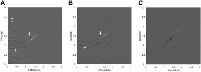
FIGURE 14. Imaging results of noised data between two weighting functions. (A) Imaging result without weighting function; (B) Imaging results using cosine function; (C) Imaging result using the variant sigmoid function.
Conclusion
Imaging of VSP data suffers more severe migration noises due to limited acquisition aperture than that of SSP data. In this paper, we give an intuitive analysis of the migration noises with synthetic VSP data. The main difference from SSP is that the noises caused by boundary truncation are enhanced by constructive interference in the vicinity of the well and cannot be reduced through multi-channel summation. These high-dip irrelevant events become the dominating noises and contaminate the imaging results. We give a brief review of the acoustic GRT migration method and extend it to weighted DDGRT by introducing a variant sigmoid weighting function to the DDCIGs. The weighted DDGRT can produce high-quality DDCIGs and is favorable for distinguishing the effective component and incoherent noise. Numerical and field data examples demonstrate that the proposed method can effectively suppress migration noises and improve imaging results.
Data availability statement
The original contributions presented in the study are included in the article/supplementary material, further inquiries can be directed to the corresponding author.
Author contributions
WL contributed to the original conception, algorithm implementation, and method validation. WL wrote the original draft of the manuscript; WM provided suggestions; QL assisted with the algorithm. All authors contributed to the study and improved the manuscript.
Funding
This work is supported by the National Key Research and Development Program of China under Grant No. 2021YFA0716802 and the National Natural Science Foundation of China under Grant No. 41904126 and No. 42130808.
Acknowledgments
We thank Optical Science and Technology (Chengdu) Ltd., for providing the field data and Engineer Jianguo Li for the professional and beneficial discussions. We sincerely thank Editor Prof. Tariq Alkhalifah for his kind help with this manuscript. Also, we appreciate the valuable comments and suggestions from the two reviewers that helped to greatly improve this manuscript.
Conflict of interest
The authors declare that the research was conducted in the absence of any commercial or financial relationships that could be construed as a potential conflict of interest.
Publisher’s note
All claims expressed in this article are solely those of the authors and do not necessarily represent those of their affiliated organizations, or those of the publisher, the editors and the reviewers. Any product that may be evaluated in this article, or claim that may be made by its manufacturer, is not guaranteed or endorsed by the publisher.
References
Beylkin, G., and Burridge, R. (1990). Linearized inverse scattering problems in acoustics and elasticity. Wave motion 12 (1), 15–52. doi:10.1016/0165-2125(90)90017-x
Beylkin, G. (1985). Imaging of discontinuities in the inverse scattering problem by inversion of a causal generalized Radon transform. J. Math. Phys. 26 (1), 99–108. doi:10.1063/1.526755
Hertweck, T., Jäger, C., Goertz, A., and Schleicher, J. (2003). Aperture effects in 2.5 D Kirchhoff migration: A geometrical explanation. Geophysics 68 (5), 1673–1684. doi:10.1190/1.1620641
Klokov, A., and Fomel, S. (2013). Selecting an optimal aperture in Kirchhoff migration using dip-angle images. Geophysics 78 (6), S243–S254. doi:10.1190/geo2013-0109.1
Klokov, A., and Fomel, S. (2012). Separation and imaging of seismic diffractions using migrated dip-angle gathers. Geophysics 77 (6), S131–S143. doi:10.1190/geo2012-0017.1
Landa, E., Fomel, S., and Reshef, M. (2008). Separation, imaging, and velocity analysis of seismic diffractions using migrated dip-angle gathers. Seg. Tech. Program Expand. Abstr. 27, 2176–2180. doi:10.1190/1.30593181
Li, W., Mao, W., Li, X., Ouyang, W., and Liang, Q. (2018). Angle-domain inverse scattering migration/inversion in isotropic media. J. Appl. Geophys. 154, 196–209. doi:10.1016/j.jappgeo.2018.05.006
Li, X., Wei, Y., and Ouyang, W. (2022). Angle-domain generalized Radon transform for elastic multiparameter inverse scattering inversion. Geophysics 87 (1), R147–R164. doi:10.1190/geo2021-0098.1
Lou, M., Cheng, D., and Doherty, F. (2009).Suppressing VSP migration artifacts and noise by selected-aperture migration and damped-least-square smoothing. SEG Technical Program Expanded Abstracts 2009, Houston, Texas, United States, 14 October, 2009. Society of Exploration Geophysicists, 4144–4148.
Lou, M., and Simpson, H. (2019).Enhancing VSP imaging quality by an efficient dip filter consistent with velocity model. 81st EAGE Conference and Exhibition 2019, Houston, Netherlands, 14 June, 2019. European Association of Geoscientists & Engineers, 1–5. doi:10.3997/2214-4609.201900698
Lüth, S., Buske, S., Giese, R., and Goertz, A. (2005). Fresnel volume migration of multicomponent data. Geophysics 70 (6), S121–S129. doi:10.1190/1.2127114
Miller, D., Oristaglio, M., and Beylkin, G. (1987). A new slant on seismic imaging: Migration and integral geometry. Geophysics 52 (7), 943–964. doi:10.1190/1.1442364
Ouyang, W., Mao, W., and Li, X. (2015). Approximate solution of nonlinear double-scattering inversion for true amplitude imaging. Geophysics 80 (1), R43–R55. doi:10.1190/geo2014-0123.1
Robein, E. (2010). Seismic imaging: A review of the techniques, their principles, merits and limitations. Houten: EAGE publications.
Safar, M. (1985). On the lateral resolution achieved by Kirchhoff migration. Geophysics 50 (7), 1091–1099. doi:10.1190/1.1441981
Schleicher, J., Hubral, P., Tygel, M., and Jaya, M. S. (1997). Minimum apertures and Fresnel zones in migration and demigration. Geophysics 62 (1), 183–194. doi:10.1190/1.1444118
Sun, J. (1998). On the limited aperture migration in two dimensions. Geophysics 63 (3), 984–994. doi:10.1190/1.1444409
Sun, S., and Bancroft, J. (2001). How much does the migration aperture actually contribute to the migration result? Seg. Tech. Program Expand. Abstr. 2001, 973–976. doi:10.1190/1.1816802
Thorbecke, J. W., and Draganov, D. (2011). Finite-difference modeling experiments for seismic interferometry. Geophysics 76 (6), H1–H18. doi:10.1190/geo2010-0039.1
Wu, J., Shi, Y., Guo, A., Lu, P., and Yang, Q. (2022). High-resolution imaging: An approach by compensating absorption and dispersion in prestack time migration with effective Q estimation and Fresnel zone identification based on deep learning. Front. Earth Sci. (Lausanne). 9, 1371. doi:10.3389/feart.2021.771570
Xue, H., and Liu, Y. (2018). Reverse-time migration using multidirectional wavefield decomposition method. Appl. Geophys. 15 (2), 222–233. doi:10.1007/s11770-018-0670-0
Yilmaz, Ö. (2001). Seismic data analysis: Processing, inversion, and interpretation of seismic data. Houston, Texas, United States: Society of exploration geophysicists.
Yilmaz, O. (1987). Seismic data processing. Investigations in geophysics. Houton: Society of exploration geophysicists.
Yu, J., and Hornby, B. (2008). A strategy for attenuating VSP migration artifacts: Local beam migration. Seg. Tech. Program Expand. Abstr. 27 (1), 3385–3389. doi:10.1190/1.3064047
Zhou, Y.-H., Gao, J.-H., Wang, B.-L., and He, Y.-Y. (2010). Migration scheme for imaging offset VSP data within local phase space. Appl. Geophys. 7 (1), 31–40. doi:10.1007/s11770-010-0003-4
Zuberi, A., and Alkhalifah, T. (2013). Imaging by forward propagating the data: Theory and application. Geophys. Prospect. 61, 248–267. doi:10.1111/1365-2478.12006
Keywords: VSP, DDCIG, migration aperture, seismic imaging, GRT
Citation: Li W, Mao W and Liang Q (2023) Imaging of vertical seismic profiling data using weighted generalized radon transform migration in dip-angle domain. Front. Earth Sci. 10:974371. doi: 10.3389/feart.2022.974371
Received: 21 June 2022; Accepted: 20 September 2022;
Published: 06 January 2023.
Edited by:
Tariq Alkhalifah, King Abdullah University of Science and Technology, Saudi ArabiaReviewed by:
Qiang Guo, China Jiliang University, ChinaLianjie Huang, Los Alamos National Laboratory (DOE), United States
Copyright © 2023 Li, Mao and Liang. This is an open-access article distributed under the terms of the Creative Commons Attribution License (CC BY). The use, distribution or reproduction in other forums is permitted, provided the original author(s) and the copyright owner(s) are credited and that the original publication in this journal is cited, in accordance with accepted academic practice. No use, distribution or reproduction is permitted which does not comply with these terms.
*Correspondence: Weijian Mao, d2ptYW9Ad2hpZ2cuYWMuY24=