 Long Jing-kui1,2*
 Yu Wen-kai
- 1School of Architecture and Design, China University of Mining and Technology, Xuzhou, China
- 2School of Mechanics and Civil Engineering, China University of Mining and Technology, Xuzhou, China
- 3Guizhou Bureau of National Mine Safety Administration, Guiyang, China
- 4Guizhou Lindong Coal Industry Co, Ltd., Guiyang, China
In view of the deformation and instability law of hard roof without side filling retaining roadway, based on the systematic construction and analysis of the force and bearing model of roadway retaining structure, this article proposes the control mechanical model and calculation method of roadway retaining, which takes the anchor roof beam and the key block above to form the cantilever beam together, with the anchor solid coal side as the foundation support. The research and practice show that under the condition of hard roof, the mechanical connection between the roof of gob-side entry retaining and the roof of mining face can be effectively cut off so as to improve the structural configuration and mechanical properties of the lateral roof of gob-side entry retaining and the key blocks above, and reduce the damage of upper strata subsidence and goaf roof collapse to the roof of roadway. Then, through strengthening by anchor to significantly enhance solid coal side, bearing capacity of anchor roof beam, so they can share the upper strata caused by the load and deflection of mining influence, in addition, the roof bolting, reinforcement of waste rock bolting supporting role can better improve the structure for stability, adaptability and engineering applicability, this method is successfully applied in engineering practice. It is worthy of further research and application.
1 Introduction
For a long time, coal pillar mining has been adopted in most mining areas of China’s coal mines, resulting in the loss of produced coal accounting for about 40% of the total coal loss of the whole mine (Chen and Lu, 1994). The pillarless mining along a gob retaining roadway can improve the mining area’s recovery rate by 10–20% and reduce the roadway driving rate by 25–30% (He et al., 2016). It can also realize y-type ventilation, control gas, relieve mining imbalance, and eliminate isolated working face. With significant economic benefits and technological advantages, it can better meet the goal of safe, economic, efficient, green, and sustainable mining. It has important strategic significance (Sun and Zhao, 1993; Qian et al., 2003).
According to roadway side support materials and action modes, it can be divided into filling support and non-filling support (Cao et al., 2016). The calculation models around the resistance of roadway side support mainly include the mechanical model of separated rock block, the mechanical model of roof tilt, the mechanical model of rectangular superimposed plate bending moment failure, the mechanical model of limit equilibrium beam of coal body, and the mechanical model of elastic thin strip (Chen, 2012). The research shows that the application and development of roadway side filling support are affected by the complexity of the process, impedance lag, and high cost, while the non-filling support can effectively avoid these problems and realize the control of roadway roof and overlying rock strata more quickly (Hua et al., 2005). In fact, most coal mines, especially small- and medium-sized coal mines, are more likely to have the way of sideway filling without lane retention when conditions permit.
He et al. (2017a, 2017b), on the basis of the “roof cutting short-boom beam theory,” have put forward new technologies such as roof cutting pressure relief and 110 construction methods in recent years, which further promote the development of roadwayless side filling and retaining technology. Pre-split cutting top is to cut off the stress transfer path between goaf and roadway roof through pre-split action, shorten the length of the cantilever beam of the roof, and help the goaf roof collapse fully. The main technologies include slit pressure relief, drilling pressure relief, blasting pressure relief, and water injection softening. Kang et al. (2014), Sun et al. (2014), Zhang (2010) and other scholars have made many valuable research achievements in this regard.
As for the role of roadway anchoring and roadway side support, one view holds that roadway anchoring and roadway side support have no fundamental influence on the broken rule of the basic roof and cannot change the broken position and shape of the roof. The other holds that different roadway anchoring and roadway side support have different influences on the position, shape, and law of the basic roof breakage, which mainly depend on the strength and stiffness of roadway anchoring and roadway side support. In fact, strengthening roadway anchoring and roadway side support can improve the broken position and structural form of the basic roof, enhance the stability and adaptability of roadway retention structure, and significantly improve the effect of roadway retention.
Based on the previous research by others, the author takes the control of retaining roadway in hard roof as there search object. By systematically constructing the force and bearing model of goaf retaining roadway with no roadway side filling (referred to as non-filling retaining roadway, the same below), the feasibility, rationality and calculation method of bearing capacity of anchoring solid coal slope, anchoring roof beam and key blocks above on the retaining roadway structure are studied. And through effective roof cutting to improve the overburden structure configuration and stress field distribution, significantly improve the stability, adaptability and engineering applicability of roadway retaining structure, promote coal mine safety, economic, efficient and sustainable production
2 The Control Principle of Hard Roof Without Filling is “Anchoring - Cutting - Supporting - Blocking - Closing”
A hard basic roof refers to a layer of hard rock with good mechanical properties, good structural integrity, and bearing capacity above the direct roof of the coal seam. The direct roof of the coal seam is generally a composite layered structure, with different strengths and stiffnesses in each layer. The bond between adjacent layers is weak, and the weak surface is developed, showing a heterogeneous layered occurrence form. In order to improve the bearing capacity of the roadway’s direct roof, it is necessary to adopt high-strength materials to coordinate and strengthen the anchoring during tunneling, so that it has high strength and high stiffness that meet the requirements of roadway retaining bearing performance. After stoping the first working face, the cantilever beam structure will not be formed together with the goaf roof due to the strength of the anchor roof beam and the key block above. Compared with ordinary roadways, the load-bearing structure of roadway retaining is changed from roof, solid coal side, gangue side and floor “tetrahedron” to roof, solid coal side and floor “trihedron.” Under the comprehensive influence of key block overturning and subsidence, upper weak rock layer, and mining, there will be separation, deformation, and failure between the anchor roof beam and the basic roof, so it is necessary to optimize the position and state of the roadway side structure and reconstruct the bearing structure. Therefore, on the basis of previous research and practice, the control principle of “anchor-cut-support-stop-close” was proposed.
For the reserved roadway, it is necessary to consider its anchorage strength and stiffness to meet the mechanical property requirements of repeated mining failure. Therefore, the roadway cannot adopt the control mode of ordinary roadway, and it needs to adopt “bolt + anchor cable + anchor net + steel belt” to strengthen the anchoring of roadway roof and solid coal side. It means that the bolts are interlocked horizontally with W steel bands, and the bolts are interlocked longitudinally with T steel bands to form “anchor cable beam.” In addition, the layout density of anchor cable beam is appropriately strengthened to effectively improve the anchoring strength and stiffness of roof and solid coal side, so as to improve their bearing capacity and anti-deformation capacity, which is the “anchor” principle. In contrast, if the mining coal gang is going to be excavated when the working face is mined, the ordinary anchoring method can be adopted, and it only needs to meet the mining impact requirements.
Because it is a hard roof and the anchoring roof beam has good bearing capacity, the basic roof will form a single cantilever beam with large span above the lateral roof and goaf, which is very unfavorable to the stability of the roadway retaining structure. Therefore, a certain distance ahead of the working face is needed to cut off the mechanical connection between the roof of the roadway and the roof of the mining face in advance. When the goaf roof collapses, the stress transfer and damage to the roof of the roadway can be significantly reduced, which is the “cutting” principle. Considering the effect and influence of periodic pressure, the top-cutting distance should be greater than the fracture length of the basic roof along the advancing direction of the working face, generally 50m ahead of the working face.
In order to enhance the stability and adaptability of the lateral roof of roadway retention and prevent large overturning and subsidence of the direct roof and the basic roof above the roadway retention, “single column + steel beam” or hydraulic support should be adopted to support the roadway side to form the roof cutting support structure. At the same time, through the joint action of roof cutting and caved gangue bursting, caved gangue usually fills the goaf and forms gangue support structure, thus forming a certain support force for the basic roof above the goaf and the lateral roof of roadway retaining. The principle of “support” is to make good use of the self-support function of gangues in goaf and the support function of roadway side cutting roof support structure.
In addition, in order to prevent the gangue in goaf from falling into the roadway, it is necessary to build a gangue retaining and supporting structure with steel beam and steel mesh before the caving, so that the gangue in goaf can form a new gangue side on the outside of the structure, which is the “retaining” principle. In addition, in order to prevent the gas or harmful gas in the goaf from spilling into the roadway and the air in the roadway from flowing into the goaf, it is advisable to use “wire mesh + sealing cloth + steel mesh” to construct a closed structure between the gangue retaining structure and the caved gangue in the goaf. If necessary, grouting or higher sealing treatment should be carried out on the gangue side, which is the “closed” principle.
As mentioned previously, by cutting the mechanical connection between the roadway and the roof of the stoping working face, the configuration and stress transfer path of the roadway retaining structure are optimized, and the roadway retaining structure is placed in the low-stress zone so as to weaken the damaging effect of upper rock strata activities on key blocks and the roadway retaining structure. On this basis, through the implementation of tunnel anchorage structure, cut the roof supporting structure and supporting structure of coal and gangue and gangue supporting structure of retaining the effective control to form has a good stability and adaptability for bearing structure, so that we can better meet the requirements of coal mining, it is the control principle of “anchor-cut - support - solid - block - close” for hard roof without filling roadway retention, as shown in Figure 1.
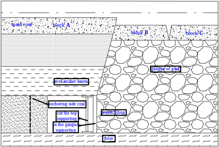
FIGURE 1. Control diagram of “anchor - cut - support - block - close” of unfilled gob-side entry retaining structure.
Compared with the side filling retaining roadway, the non-filling retaining roadway has high efficiency, simple construction process and technology, and most of its supporting materials can also be recycled, which significantly saves production cost. In addition, the bearing performance of the roadway roof and solid coal side can be adjusted by changing the control mode and parameters, including cutting roof support which has strong controllability, and it is easier to realize the cooperative bearing between them. For the hard layered roof, it is undoubtedly effective, efficient, and applicable to use this control principle and technology to realize lane retention, and it also has an important reference value for other conditions of roof lane retention. For example, under the condition of a thick layer soft rock roof of a coal mine in Guizhou, the authors successfully retained the roadway by effectively cutting the roof, strengthening the anchoring in the roadway, and cutting the roof support.
3 Migration Law of Hard Roof Without Filling Retaining Roadway
According to the cantilever beam hypothesis, masonry beam mechanical model, transfer rock beam mechanical model, key layer theory, large–small structure stability principle, and other theories (Allard and Swelsky, 1986; Zhu, 1987; Song, 1988; Qian, 1994; Ortlepp and Stacey, 1998; Hou and Li, 2001; Qian et al., 2010; Chen, 2012; Yuan et al., 2013), the key layer that has the greatest influence on the entry retention is mainly the basic roof, and the fracture position of the basic roof determines the structural characteristics of the lateral roof strata of the stope. It is necessary to study the influence of fracture, movement, and stability of the basic roof on the stability of roadway retaining structure. With the advancement of the working face, the overlying strata of the goaf collapsed, and the “O-X” fracture was formed by the initial pressure on the basic roof, while the masonry beam structure was formed along the direction of the working face by periodic pressure, and the curved triangle block was formed at the end of the working face. As for the filling and retaining roadway beside the roadway, due to the hysteresis of the loading at the side of the roadway, the arc-shaped triangular block will fracture, rotate, and sink under the overburdening pressure. Usually, the first fracture occurs above the side of the solid coal body, and finally three blocks A, B, and C are formed, as shown in Figure 2A.
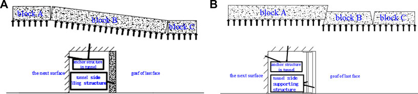
FIGURE 2. Schematic diagram of basic roof fracture. (A) Filling retaining roadway, (B) no filling entry.
Compared with ordinary roof roadway, the periodical pressure of hard roof stope is more intense, which is unfavorable to control the stability of roadway retention. However, according to the control principle of the hard roof, as the roof of roadway and the roof of working face have been effectively cut off, two blocks A and B are formed on the basic roof before mining. Under the advanced action of periodic pressure, the cutting condition between block A and B will be further intensified, and certain slippage and spacing will occur along the cutting surface. When the working face is pushed, the direct roof above the mined coal seam collapses first, which provides space for the settlement of the upper basic roof. Subsequently, block B will have obvious settlement, and the scattered between block A and block B will further increase, which is mainly related to the degree of gangue filling in the goaf and the degree of upper rock subsidence. Due to differences in structural performance and settlement sequence of the goaf roof, block B will also fracture during settlement, forming new blocks B and C, which are finally compacted on the gangue structure of goaf, as shown in Figure 2B. Therefore, to master the basic law of hard roof stope mine pressure, a reasonable control mode of roadway retention is adopted, which is the key to the safety of stope production and the stability of roadway retention structure.
4 Stability Control Mechanism of Roadway Retaining Without Filling in Hard Roof
4.1 Stress and Load-Bearing Model of Roadway Retaining Structure
For the hard roof, the mechanical properties, fracture position, and geometric parameters of block A on the roof of entry retention are the key factors affecting the stability of entry retention structure. Under the action of its upper strata and its own gravity, block A will transfer the load to the anchoring roof beam in the way of bending subsidence, and then the anchoring roof beam will transfer to the roadway retaining structure such as a solid coal wall, cutting roof support in a similar way. In order to simplify the construction of the mechanical model, it is assumed that 1) roadway roof and working face roof, especially block A and block B, can be effectively cut off; 2) the load generated by the rock strata at the basic top is mainly transmitted to the gangue of the entry retaining structure and the goaf through block A, B, and C, respectively; 3) through the synergistic anchoring effect of anchor rods, anchor cables, and composite components, the roadway roof is directly anchored into an integral rock beam, which forms a cantilever beam structure together with block A and plays a major role in the stability of roadway retention; and 4) the solid coal seam is continuous, homogeneous, and isotropic.
According to the control principle of the hard roof without filling and roof migration law, after the first working face is pushed over, the roadway retention structure mainly bears the load imposed by the self-gravity G1 of soft rock in the upper part of block A, the bending load G2 of block A, and the bending load G3 of the anchoring roof beam. The supporting force F1 of the solid coal side, the bearing capacity F2 of block A, the bearing capacity F3 of the anchoring roof beam, the supporting force F4 of roof cutting support, the supporting force F5 of gangue retaining support, the supporting force F6 of goaf gangue supporting block B, the lateral supporting force F7 of roadway roof, and the lateral supporting force F8 of block B supporting block A are jointly undertaken. Thus, taking the boundary line of the loose area of solid coal side and the intersection point O under roadway roof as the origin, the force and bearing model of roadway retaining structure is established, as shown in Figure 3A. The basic mechanical equation of roadway retaining structure is as follows:
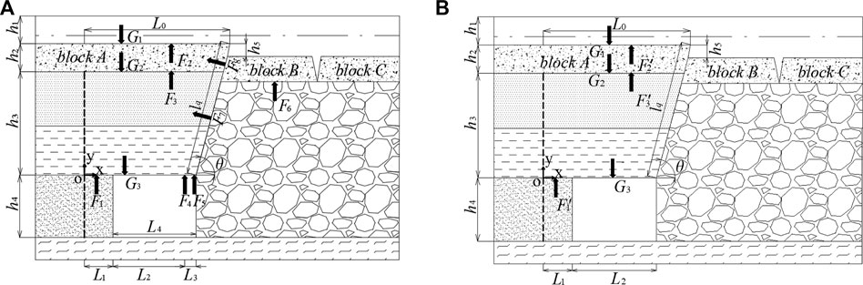
FIGURE 3. Structural mechanics model diagram of gob-side entry retaining without filling. (A) Stress and load bearing model diagram, (B) stability control model diagram.
Formula (1) considers the balance relationship between the force and load of the roadway retaining structure. When this relationship is satisfied, the roadway retaining structure is in a stable state.
4.2 Stability Control Mechanism of Roadway Retaining Without Filling in Hard Roof
According to Formula (1), as long as the equilibrium state is not broken, the lane retention structure can remain stable. For actual engineering conditions, the basic structure remains the same, the change of movement is produced by the mining effect, and the structure bearing capacity because the control mode, control parameters and controlled time different and change, That is, the structural bearing capacity is variable, when a lack of structure bearing capacity and advance damage can cause the structure for the overall destruction and instability. Therefore, it is necessary to optimize the mechanical model and calculation method of load-bearing structures from the perspective of enhancing the stability of retaining structure.
In practical engineering, this article considers that gangue may not be able to fill the goaf in time, which may result in insufficient support force F6 of gangue on block B, lateral support force F7 on roadway roof, and lateral support force F8 of block B on block A, and limited support force F4 of roof cutting support and F5 of gangue retaining support. Therefore, F4 ∼ F8 on the left of Formula (1) is not included in the calculation of roadway retaining structure bearing capacity. In this case, the bearing capacity of anchoring solid coal wall and roof anchoring beam needs to be realized by strengthening anchoring, while the bearing capacity of block A can be realized by effectively cutting the roof and forming a short arm beam, as shown in Figure 3B:
where
Formula (2) shows that under the condition of hard roof, if only the anchoring coal slope is considered, the anchoring roof beam and block A withstand, respectively, from deflection of strata above the load, and the load is realized by strengthening the anchoring or structural optimization; then, combined with the “reinforcing bearing” effect of F4 ∼ F8 forces, the roadway retaining structure will be more stable because top-cutting support, retaining gangue support, and gangue support exist objectively. Notably, it is of great significance to carry out such treatment, which is the stability control mechanism of retaining the roadway without filling in the hard roof. The next step is to calculate the bearing capacity and related parameters of the anchoring solid coal wall, anchoring roof beam, and block A, which meet the requirements of Formula (2).
4.3 Mechanical Calculation of Stability Control Model of Roadway Retaining Structure
As shown in Figure 3B, according to the stability control mechanism of unfilled roadway retention in hard roof, and on the basis of satisfying the relationship between force and bearing capacity in Formula (2), load-bearing performance, relevant mechanical parameters and control requirements should be provided by anchoring solid coal slope, anchoring roof beam and upper block A can be designed and constructed to provide load-bearing structure with good stability. Thus, the theoretical research is transformed into engineering practice, and verified and optimized in practice. Thus, the stress diagram of anchoring roof beam and block A is established, as shown in Figure 4.
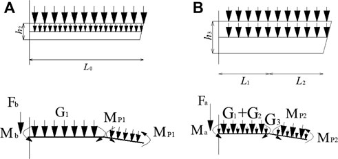
FIGURE 4. Stress diagram of anchoring roof beam and block A. (A) Block A, (B) anchor roof beams.
4.3.1 Block A Geometric Parameters
1) Fracture length of the basic roof along the advancing direction of the working face. It can be obtained through on-site mine pressure monitoring or theoretical calculation (Qian et al., 2010):
where L is the fracture length of the basic roof along the advancing direction of the working face, m;
2) The basic roof along the lateral fracture span. According to the yield line analysis of the plate (Jiang, 1993), it is considered that the lateral fracture span of block A is related to the length of the working face and the periodic compression step of the basic roof can be written as:
where
3) Width of the loose zone of the solid coal wall. Under the influence of mining, the solid coal will form a certain loose area. The basic roof rock is regarded as a semi-infinite beam, and the elastic foundation beam model is used to obtain the width of the loose zone of solid coal wall (Qian and Zhao, 1987; Qian and He, 1989):
where
4.3.2 Pre-Split Cutting Top Parameters
Under the condition of hard roof, the lateral fracture span
where
In order to make block A, the anchoring roof beam can form a short cantilever beam; the cutting angle is generally 5–10°, but it needs to be determined according to coal seam dip angle and roof rock structure to ensure the formation of a short-boom beam structure. According to Eqs 4 and 6, when
where
4.3.3 Self-Gravity of Upper Strata of Block A
Under the influence of mining, the upper weak rock layer will separate and sink, and act on block A in the way of self-gravity:
where
4.3.4 Bearing Capacity of Block A
As shown in Figure 4A, block A is subjected to force and load in the form of fixed beam, that is, the left boundary is constrained by the fixed end. When conducting mechanical analysis and calculation, lifting the fixed constraint is equivalent to bending moments Fb and Mb. According to the balance equation of bending moment and force, the following equation can be obtained:
where
where
where φ is the friction angle within the rock layer and
In addition, according to relevant formulas of material mechanics,
where σ is the tensile stress at the cutting position of block A, kN; [σ] is the flexural strength of block A, kN/mm2;
When Eqs 15 and 16 are satisfied, block A will not suffer from buckling failure. It can be seen that the mechanical properties of block A for the stability of entry retention can be obtained by changing the angle of cutting top and geometric parameters of entry retention structure, so that block A can remain stable.
4.3.5 Bearing Performance of Anchoring Roof Beams
As shown in Figure 4B, according to the mechanical characteristics of the hard roof, the anchoring roof beam is simplified as the cantilever beam for mechanical calculation. The left boundary of the beam is assumed to be a fixed end constraint. When mechanical analysis and calculation are carried out, lifting the fixed constraint is equivalent to bending moment Fa and Ma. According to the balance equation of bending moment and force, the following equation can be obtained:
where
where
In addition, according to the formula of rectangular section stress calculation of material mechanics, the stress of beam per unit width is calculated as follows:
where
When Eqs 23 and 24 are satisfied, the anchoring roof beam will not bend and sink. It can be seen that the mechanical properties of the anchoring roof beam can be obtained by changing the cutting angle, geometric parameters of roadway retaining structure, and anchoring parameters of roadway roof, so that the anchoring roof beam can remain stable.
4.3.6 Anchor Solid Coal Side Support Force
During the process of roadway excavation to retaining, the stress of solid coal wall will be redistributed and abutment pressure will be formed at its wall. Under the premise of no control of the solid coal seam, the solid coal seam is subjected to vertical load, and two regions, namely, limit equilibrium zone and elastic zone, which will appear successively, as shown in Figure 5A.
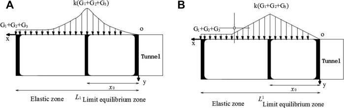
FIGURE 5. Force model of solid coal wall. (A) Stress distribution model, (B) simplified model of force.
Due to the irregularity of the stress characteristics of coal seam, the abutment pressure above the solid coal seam is simplified as a linear distribution form for convenient discussion (Ke, 2020). Taking any unit body within a certain range of solid coal seam as the research object, the abutment pressure above the solid coal seam can be regarded as two load distribution forms of uniform distribution and linear distribution, and its stress-simplified model can be obtained, as shown in Figure 5B. According to the analysis principle of stress components of a semi-infinite body under normal load, the stress components
1) Linear load in limit equilibrium zone:
2) Uniform load in elastic zone:
3) Linear load in elastic zone:
By determining the stress component of any point in coal seam rock mass under the action of abutment pressure of each part, the stress component of this point can be obtained from the theory of elasticity:
Based on the Moore Coulomb criterion, the ultimate compressive strength of the anchored solid coal seam under triaxial stress is (Hui, 2021):
where [
Then, according to the formula of extreme value of mechanical normal stress of material:
where
Finally, for safety reasons, the third strength theory is adopted, and the ultimate condition of instability failure of anchored solid coal wall is:
where
When Eq. 37 is satisfied, in other words, the stress at any point in the anchoring solid coal wall is less than its ultimate compressive strength, and the anchoring solid coal wall will not be damaged under compression. It can be seen that by strengthening the anchoring of the solid coal slope, changing its mechanical property parameters and crushing range to obtain the mechanical properties of the solid coal slope for the stability of roadway retention, the stability of solid coal slope can be maintained and the structure of roadway retention is more stable.
4.4 Cooperative Bearing Relationship of Roadway Retaining Structure
Based on the previous analysis and calculation, relevant structural and mechanical properties parameters required to meet the stability of roadway entry retention can be obtained by changing the cutting angle, the anchoring performance of roadway solid coal wall and roof, and the geometric parameters of key blocks, so as to realize the construction and control of roadway entry retention structure. According to the stability control mechanism of roadway retaining structure, the following synergistic relationships should be satisfied among key load-bearing structures:
1) When the roof lithology is poor and the strength and stiffness of the anchoring roof beam are insufficient, it is necessary to take effective ways to enhance the synergistic support effect of anchoring solid coal side, roof cutting support structure, retaining gangue support structure, and gangue support structure to realize the reinforcement control of the anchoring roof beam;
2) When the coal is soft and the bearing capacity of the anchoring coal seam is insufficient, the bearing capacity of the anchoring roof beam, the cutting roof support structure, and the gangue support structure should be strengthened to reduce the stress transfer and damage of the solid coal seam in the upper strata;
3) When the goaf roof caving is not sufficient and the bearing capacity of gangue support structure is limited, the anchorage strength and stiffness of roadway roof and solid coal side should be further improved, and the supporting force of roof cutting support structure should be increased to adapt to the destruction caused by the violent movement of overburdened strata;
4) By contrast, cutting roof bolting controllability is strong, according to the roof, solid coal wall, gangue collapse degree and so on, the supporting force in the roadway and the side of the roadway can be adjusted. For example, to improve the support density or adopt hydraulic support, can effectively improve the bearing capacity of the roof support, and even play a key bearing role. There are also examples of the use of dense pillar to successfully retain the roadway.
5 Field Test
5.1 Engineering Conditions
According to the aforementioned research methods, the practice of retaining roadways was carried out in the haulage lane of 5,921 working faces of the Longfeng Coal Mine in Guizhou province. The average thickness of the coal seam is 2.0 m, and the direct roof is a gray medium thick-bedded argillaceous siltstone with obvious horizontal bedding. There are soft rocks, thin coal seams, or coal lines in the middle, and the old roof is light gray medium thick-bedded fine sandstone with good stability. The direct bottom is a gray thin-bedded argillaceous siltstone, showing horizontal bedding. There is a floor-heave phenomenon during driving.
5.2 Anchorage Structure Design of Retaining Roadway
According to the control mechanism of non-filling lane retention and combined with the actual situation of the transport lane, the scheme design of important processes such as roadway anchor solid, roadway side support body, and directional blasting pre-splitting cutting roof were systematically carried out, as shown in Figure 5.
5.2.1 Control Parameters of Anchoring Roof Beam
Each section of the roof is drilled with 6 high-strength bolts. Because the loose ring is about 2,000 mm, the bolt specification is φ 20 × 2,500 mm, and the row distance is 700 × 800 mm. Located in the roof on the shoulder angle of mining face bolt straight drill, the roof shoulder angle of solid coal bolt and plumb line form 30°; Bolt preload is 100 kN. A total of 4 anchor cables were drilled, among which the second anchor cable by the stoping side was φ 17.8 × 9,200 mm, which was drilled straight. The angle between the anchor cable at the shoulder angle of solid coal and the plumb line is 30°. The other two anchor cables are drilled vertical to the roof, with specifications of φ 18.9 × 7200 mm. The spacing of anchor cables is shown in the figure, and the row spacing is 1,600 mm. Anchor cable preload is 200 kN.
5.2.2 Control Parameters of Anchoring Solid Coal Seam
Each section of solid coal wall is drilled with 4 bolts, and the row spacing is 800 × 800 mm. Other parameters are the same as those mentioned previously. In order to enhance the bearing performance of solid coal seam, two φ 17.8 × 4200 mm short anchor cables are drilled in each section with row spacing of 1,600 × 1,600 mm. Other parameters are the same as those mentioned previously.
5.2.3 Control Parameters of Pre-Split Cutting top
The roof is cut by directional blasting, with a hole depth of 8,000 mm, drilling angle of 150, and distance of 600 mm. There are 8∼10 holes in the same group of initiation. The cutting top position is always about 50 m ahead of the working face, and pre-crack detection is carried out every 20 m to ensure the cutting top effect.
Other control parameters are shown in Figure 6.
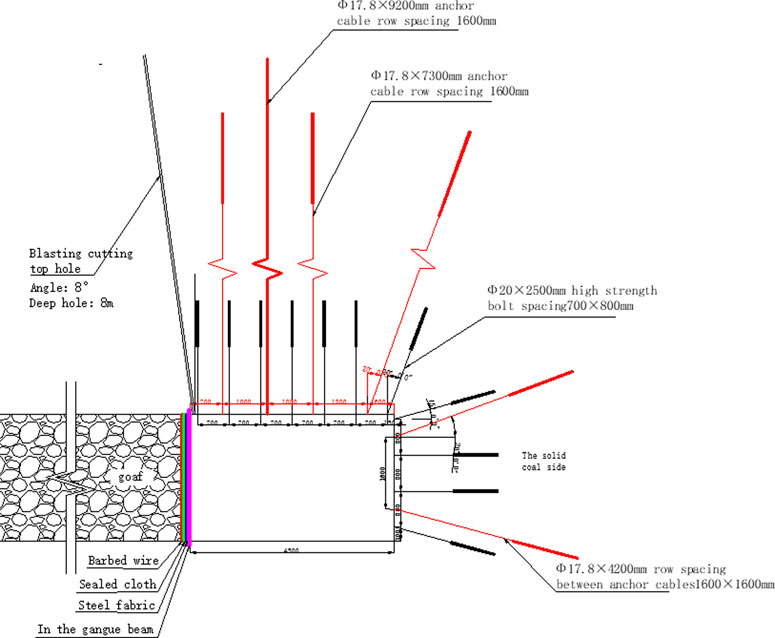
FIGURE 6. Gob-side entry retaining design drawing of 5,921.
5.3 The Control Effect
From the end of roadway excavation to the end of roadway retention, the construction quality inspection of anchor net cable, the stress monitoring of roadway deformation ,and anchor bolt (cable) are strengthened to ensure the construction quality and achieve the expected control effect.
As shown in Figure 7, during roadway excavation, the maximum subsidence of the roof is no more than 15 mm, and the shrinkage of two sides is no more than 30 mm, indicating that strengthened anchoring significantly improves the strength and stiffness of roadway anchoring surrounding rock. During roadway retention, except for some small sections such as drilling field and fault, the maximum subsidence of roof under normal conditions is not more than 260 mm, and the shrinkage of two sides is not more than 180 mm, indicating that the anchorage structure of roadway retention has better stability and adaptability, and achieved better control effect.
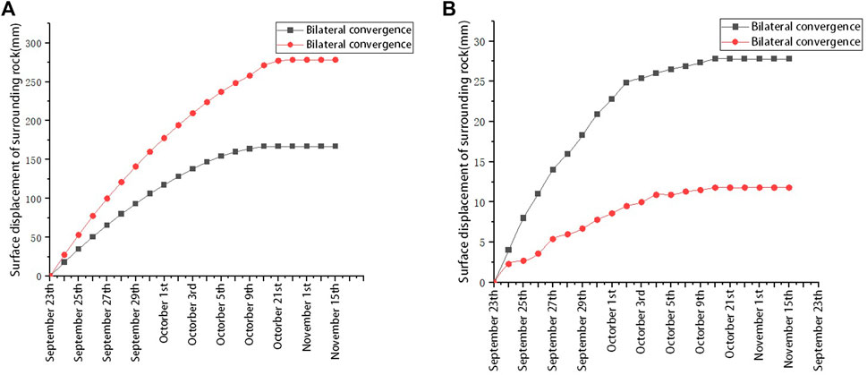
FIGURE 7. Monitoring chart of 5,921gob-side entry retaining deformation. (A) During the drivage, (B) during the left lane.
As shown in Figure 8 and Figure 9, the maximum axial force of bolt and cable during lane retention is no more than 140 and 220 kN, which are close to their initial anchoring force, with uniform force and no obvious stress concentration phenomenon, indicating that bolt and cable realize cooperative bearing and achieve the expected effect.
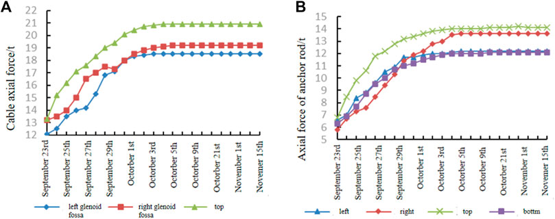
FIGURE 8. Anchor–anchor cable stress monitoring chart. (A) Anchor, (B) Anchor cable.
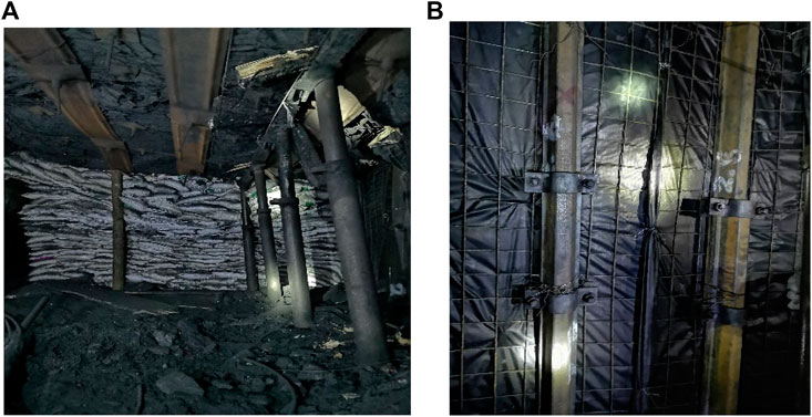
FIGURE 9. Actual effect drawing of gob-side entry retaining. (A) Roof cutting support and lane retention space, (B) gangue retaining and support.
6 Conclusion
1) In view of the law of retaining roadway with hard roof and deformation and instability of overlying strata, the author take reasonable way to cut off the roof and the working face roof for the mechanical contact, to improve the position and state of strata structure and stress field distribution and reduce mining face goaf roadway roof caving the roof damage, so more conducive to the structural stability for control.
2) In this paper, combined with the actual construction of unfilled roadway retaining force and bearing model, the bearing characteristics of each bearing structure are analyzed, and it is proposed that the roadway solid coal side and roof are taken as the key bearing structures, and their bearing performance can be significantly improved by strengthening the anchoring effect, so that they jointly bear the bending load and mining influence imposed by the upper strata. The stability and adaptability of the whole roadway retaining structure can be improved by the reinforcing support of cutting roof support and gangue support.
3) Engineering practice shows that the control effect of unfilled roadway retention can be significantly improved by enhancing the cooperative bearing capacity of roadway anchorage structure and roadway side support structure, and the technical problems and difficulties in engineering practice are effectively solved.
4) In this article, the hard roof without filling roadway retention is taken as the research object, and the corresponding mechanical model and calculation method are established, which can provide a reference for other conditions of roof roadway retention and is worthy of further research and promotion.
Data Availability Statement
The raw data supporting the conclusions of this article will be made available by the authors, without undue reservation.
Author Contributions
LJ-K: In view of the deformation and instability law of the hard roof non-roadway side filling retaining roadway, the stress and bearing model of the retaining roadway structure is systematically constructed. The mechanical model and calculation method of the retaining roadway supported by the cantilever beam formed by the anchored roof beam and the key blocks above and the anchored solid coal wall are proposed. The technical scheme and relevant parameters of the engineering practice are designed, and the engineering test is guided. The first draft of this paper is written. QC-X, CZ-Y, LH, and YW-K: Participated in the theoretical analysis, engineering test scheme design, field implementation, and paper modification of the control of hard roof side entry filling and retaining roadway.
Funding
The research was supported by the National Natural Science Foundation of China, 52174136.
Conflict of Interest
LH was employed by Guizhou Lindong Coal Industry Co, Ltd.
The remaining authors declare that the research was conducted in the absence of any commercial or financial relationships that could be construed as a potential conflict of interest.
Publisher’s Note
All claims expressed in this article are solely those of the authors and do not necessarily represent those of their affiliated organizations, or those of the publisher, the editors, and the reviewers. Any product that may be evaluated in this article, or claim that may be made by its manufacturer, is not guaranteed or endorsed by the publisher.
References
Allard, K., and Swelsky, T. B. (1986). Prediction Method of Roof Collapse. American Society of Mining Engineers. Status Quo of Rock Strata Control and Subsidence Prevention Technology in Longwall mining[C]. Taiyuan: Shanxi Science Education Press.
Cao, S. G., Chen, X. Z., Yang, H. Y., Wang, S., and Zou, D. J. (2016). Analysis of Side Control Technology and Applicable Conditions for Gob-Side Entry Retaining [J]. Coal Sci. Technol. 44 (4), 27–33.
Chen, Y. (2012). Study on Stability Mechanism and Control of Surrounding Rock Structure Movement of Gob-Side Entry retaining[D]. Xuzhou: China University of Mining and Technology.
Chen, Y. G., and Lu, S. L. (1994). Surrounding Rock Control of Coal Mine Roadway in China[M]. Xuzhou: China University of Mining and Technology Press.
He, M. C., Chen, S. Y., Guo, Z. B., Yang, J., and Gao, Y. B. (2017b). Structural Control and Engineering Application of Surrounding Rock of Gob-Side Entry Retaining with Roof Cutting Pressure Relief [J]. J. China Univ. Min. Technol. 46 (9), 959–969.
He, M. C., Song, Z. Q., Wang, A., Yang, H. H., Qi, H. G., and Guo, Z. B. (2017a). The Theory and 110 Construction Methods of Short-Wall Beam Cutting in Longwall Mining -- the Third Mining Science and Technology Reform[J]. Coal Sci. Technol. (1), 1–9+13.
He, S. D., Zhang, Y., and Liu, W. (2016). Research Status and Prospect of Gob-Side Entry Retaining Technology[J]. Mod. Min. 563 (3), 6–10.
Hou, C. J., and Li, X. H. (2001). Stability Principle of "large and Small" Structure of Surrounding Rock of Gob-Side Entry Retaining in Fully Mechanized [J]. J. China coal Soc. 26 (1), 1–7.
Hua, X. Z., Ma, J. F., and Xu, T. J. (2005). Study on Surrounding Rock Control Mechanism of Gob-Side Retaining Roadway with Anchor Cable Reinforcement and its Application[J]. Chin. J. Rock Mech. Eng. 12, 2108–2112.
Hui, X. D. (2021). Narrow Section Bearing Evolution Characteristics and Coal Pillar Stability Control [D]. Master thesis. Xuzhou, China: China University of Mining and Technology.
Jiang, J. Q. (1993). Stress and Movement of Surrounding Rock in Stope [M]. Beijing: Coal Industry Press.
Kang, H. P., Zhang, X., Wang, D. P., Tian, J. Z., Yi, Z. Y., and Jiang, W. (2022). Control Technology and Application of Surrounding Rock in Pillar - Free Mining[J]. J. Coal Soc. 47 (1), 16–44.
Ke, D. (2020). Close Distance Coal Seam Roadway Deformation Law of Surrounding Rock and the Control Technology Research [D]. Master thesis. Xi’an, China: Xi 'an University of Science and Technology.
Ortlepp, W. D., and Stacey, T. R. (1998). Performance of Tunnel Support Under Large Deformation Static and Dynamic Loading. Tunn. Undergr. Space Technol. 13 (1), 15–21. doi:10.1016/S0886-7798(98)00022-4
Qian, M., and He, F. (1989). The Behavior of the Main Roof in Longwall Mining-Weighting Span,fracture and Disturbance[J]. J. Min. Metal. Fuel. 37, 240–260.
Qian, M., and Zhao, G. (1987). “The Behavior of the Main Roof Fracture in Longwall Mining and its Effect on Roof Pressure,” in 28th US symposium on Rock Mechanics, June 29–July 1, 1987 (Tucson, Arizona: ARMA-87-1123).
Qian, M. G., Shi, P. W., and Xu, J. (2010). Mine Pressure and Strata control[M]. Xuzhou: China University of Mining and Technology Press.
Qian, M. G. (1994). Stability of Masonry Beams and its Application[J]. Mine Press. Roof Manag. 3, 6–10.
Qian, M. G., Xu, J. L., and Miao, X. X. (2003). Green Mining Technology of Coal Mine[J]. J. China Univ. Min. Technol. 32 (4), 343–347.
Song, Z. Q. (1988). Practical Mine Pressure and control[M]. Beijing: China University of Mining and Technology Press.
Sun, H. H., and Zhao, B. L. (1993). Theory and Practice of Gob-Side Entry Retaining [M]. Beijing: China Coal Industry Press.
Sun, X. M., Sun, X. M., Liu, X., Liang, G. F., Wang, D., and Jiang, Y. L. (2014). Research on Key Parameters of Gob-Side Entry Retaining in Thin Coal Seam under Pressure Relief by Cutting Roof[J]. Chin. J. rock Mech. Eng. 33 (7), 1449–1456.
Yuan, L., Yuan, L., Xue, J. H., Zhang, N., and Lu, P. (2013). Present Situation and Prospect of Key Technologies of Coalbed Methane Extraction and Co-extraction of Coal and Gas[J]. Coal Sci. Technol. 41 (9), 6–11.
Zhang, G. F. (2010). Research on the Mechanism and Key Technology of Gob-Side Entry Retaining Formation by Cutting Roof Pressure relief[D]. Beijing: China University of Mining and Technology.
Keywords: hard roof, gob-side entry retaining, no gateway sidewall back, stability control, mechanical model
Citation: Jing-kui L, Chao-xin Q, Zuo-yong C, Hong L and Wen-kai Y (2022) Study on Stability Control of Gob-Side Entry Retaining Structure Without Filling Wall in Hard Roof. Front. Earth Sci. 10:970912. doi: 10.3389/feart.2022.970912
Received: 16 June 2022; Accepted: 21 June 2022;
Published: 23 August 2022.
Edited by:
Shuren Wang, Henan Polytechnic University, ChinaReviewed by:
Zhengzheng Cao, Henan Polytechnic University, ChinaXiangjun Chen, Henan Polytechnic University, China
Copyright © 2022 Jing-kui, Chao-xin, Zuo-yong, Hong and Wen-kai. This is an open-access article distributed under the terms of the Creative Commons Attribution License (CC BY). The use, distribution or reproduction in other forums is permitted, provided the original author(s) and the copyright owner(s) are credited and that the original publication in this journal is cited, in accordance with accepted academic practice. No use, distribution or reproduction is permitted which does not comply with these terms.
*Correspondence: Long Jing-kui, amtsb25nQGN1bXQuZWR1LmNu