- 1State Key Laboratory of Geohazard Prevention and Geoenvironment Protection, Chengdu University of Technology, Chengdu, China
- 2College of Environment and Civil Engineering, Chengdu University of Technology, Chengdu, China
- 3Major Hazard Measurement and Control Key Laboratory of Sichuan Province (Sichuan Academy of Safety Science and Technology), Chengdu, China
The dynamic response of rock mass is largely restricted by its joint surface. Previous studies have shown that the degradation of joint surface can not be ignored when calculating the shear strength of structural plane under cyclic load. Although several studies have attempted to calculate the cyclic shear strength of a rock mass joint surface, an established and reliable method for calculating the cyclic shear strength of rock mass discontinuities is still lacking, thus necessitating further research. In this study, the deterioration effect of the shear strength of the joint surface under cyclic shearing was first analysed using cyclic shearing tests. The influence of vibration degradation in rock mass on the structural surface, undulant angle equation of the joint surface, and calculation method for the basic friction angle under a cyclic shearing load are proposed. Furthermore, the calculation method for the shear strength of the structural surface under the action of cyclic shearing is established. The proposed method is further validated through case analysis. The influence of the cutting and filling (produced during the shearing process) on the shear strength of the joint surface cannot be disregarded. The improved model proposed in this study is in good agreement with the experimental results; however, when the improved proposed method is used to estimate the cyclic shear strength of the joint surface where the normal stress is too large, calculation results may contain certain errors.
1 Introduction
The rock mass joint surface is a two-dimensional geological interface with a particular direction, large extension, and small thickness of various structural relics (including faults, joints, bedding, and fractured zones) produced in the rock mass under the action of tectonic stress. The dynamic response of a rock mass is largely restricted by its joint surface (Wang and Zhang, 1982; Fox et al., 1998; Siad 2003; Liu 2017; Hu et al., 2020; Cui et al., 2021; Fw et al., 2021; Zhang et al., 2021). Therefore, the study of the dynamic characteristics of the joint surface, especially the dynamic shear characteristics, is an important prerequisite for the analysis of the dynamic response of a rock mass. Generally, seismic load is both dynamic and cyclic, and when a rock slope is under dynamic cyclic shearing action, the strength of its joint surface is reduced (Jafari et al., 2003; Barla et al., 2010; Woo et al., 2010; Atapour and Moosavi, 2014; Barton 2020; Zhou et al., 2021; Han et al., 2022), thereby easing the dislocation and slip of the slope along the joint surface (particularly the bedding rock slope), and resulting in geological disasters (Bhasin et al., 2004; Huang and Li, 2009; Moriya et al., 2010; Cui et al., 2013; Chen et al., 2020; Li et al., 2021a, 2021b, Li 2022a; Li 2022b). Therefore, the strength degradation and deformation mechanism of the rock mass joint surface under dynamic cyclic shear load is an essential scientific issue that needs to be addressed for the prevention and control of engineering earthquakes.
Experimental research on the mechanical behaviour of a rock mass forms the basis for the development of its constitutive model. Several studies have used physical tests to investigate the mechanical properties of structural surfaces under cyclic shear loads. For example, Jafari et al. (2003) used cement mortar to produce regular zigzag and natural joint surfaces in batches. Moreover, they analysed the shear characteristics of rock mass structural surfaces that exhibited changes in normal load, cyclic shear number, and shear rate. Fathi et al. (2016) fabricated natural unweathered granite structural surfaces with varying degrees of undulation using cement mortar and carried out cyclic shear tests. They found that the roughness and shear parameters of the joint surface decreased following an increase in the number of shear cycles. Xia et al. (2012) conducted cyclic shear tests on joint surfaces under different normal stresses and found that as the normal stress increased, the peak shear strength of the same route in the same cycle increased. In addition, the shear strength of the rock joint surface decreased as the cyclic shearing times increased. Premadasa et al. (2012) conducted cyclic shear tests on rock mass joint surfaces and showed that joint surfaces gradually transitioned from slip failure to shear failure following an increase in normal stress. Furthermore, they observed that the shear strength of the rock mass joint surface decreased as the number of cyclic shearing cycles increased and the shear failure of the joint surface mainly occurred in the initial shearing stage. Mirzaghorbanali et al. (2014) conducted cyclic shear tests with different normal stresses and shear rates on artificially fabricated joint surfaces and discussed the failure characteristics of joint surfaces in detail. Qu (2018) used cement mortar to replicate shear joint surfaces and split joint surfaces in batches, and studied the evolution characteristics of shear stress and normal displacement of different joint surfaces through cyclic shear tests. The cyclic shear testing of the various rock mass joint surfaces showed that their degradation under cyclic loads is complex, and that the performance degradation is mainly reflected as follows: 1) under the cyclic shear of the seismic load, the undulant angle decreases, and 2) under a dynamic load, the friction coefficient of the structural surface is reduced.
The accurate evaluation of the shear strength of rough rock joints has been a constant pursuit among rock mechanics research workers (Xie et al., 2022). Researchers have proposed various shear constitutive models for cyclic and dynamic load conditions based on test results and the elastoplastic theory. Plesha (1987) proposed that the joint surface undulant angle gradually degenerates under cyclic shear loading. Huang et al. (1993) performed cycle tests on sawtooth samples and verified the degradation law proposed by Plesha (1987). Qiu et al. (1993) regarded structural surface wear as plastic deformation and proposed a function of tangential plastic work as an index for expressing wear. Furthermore, they established an elastoplastic constitutive model considering the dilatancy angle and wear parameters. Divoux et al. (1997) proposed a cyclic shear mechanics constitutive model for joint surfaces based on the results of numerous cyclic shear tests. Homand et al. (2001) studied the dilatation and wear characteristics of the joint surface during the cyclic shearing process of an artificial granite joint surface using cyclic shear tests. The empirical formula for the cyclic shear strength of the rock mass joint surface was proposed by fitting. Lee et al. (2001) performed in-depth analysis of the evolution characteristics of shear stress and normal displacement through the cyclic shear test of the rough joint surface of the rock mass, and proposed a cyclic shear elastic-plastic constitutive model. Liu et al. (2013) comprehensively analysed the deformation failure characteristics and peak shear strength degradation effect of joint surfaces during the cyclic shearing process through experiments, and proposed a formula for calculating the cyclic shear strength of joint surfaces based on the test data. Mroz and Giambanco. (2015) described microscopic effects such as debonding, slippage, and dilatancy of the micro convex body through the interaction of spherical structural surfaces and proposed a constitutive model that can effectively simulate the softening phenomenon after the first cycle. While these studies have contributed significantly to the calculation of the cyclic shear strength of rock mass discontinuities, the methods used have neither been verified nor established as reliable, and should be studied further.
In this study, the deterioration of the shear strength of a joint surface under cyclic shearing was analysed using cyclic shearing tests. The influence of vibration degradation in rock mass on the structural surface, undulant angle equation of the joint surface, and calculation method for the basic friction angle under a cyclic shearing load are proposed. A calculation method for the shear strength of the joint surface under the action of cyclic shearing is established. The results of this study are expected to provide a theoretical basis for the stability analysis of rock slopes under seismic loads.
2 Cyclic shear testing of the joint surface
2.1 Experimental method
Numerous studies have shown that the artificial sawtooth structure in the cyclic shear test can reflect the deformation and failure characteristics of the structure during the shearing process to a certain extent. However, this structure cannot accurately reflect the change in the joint roughness coefficient (JRC) of the joint surface. In this study, cyclic shear tests of sandstone split joint surfaces (Figures 1, 2) carried out by Qu (2018) were used to illustrate the deterioration in the shear strength of the joint surfaces during cyclic shearing. The split joint surfaces of the sandstone were replicated using plain concrete with a cement:sand:water mass ratio of 3:2:1. Table 1 lists the basic mechanical parameters of plain concrete and sandstone, showing that the selected materials have mechanical properties that are similar to those of sandstone (Qu 2018; Dong et al., 2020).
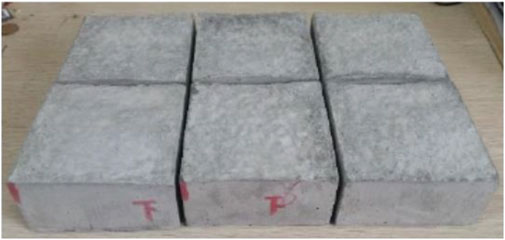
FIGURE 1. Upper and lower parts of the splitting structural plane (Qu 2018).
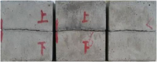
FIGURE 2. Anastomotic splitting structural plane (Qu 2018).

TABLE 1. Mechanical parameters of sandstone and similar materials (Qu, 2018).
Based on the direct shear test of 136 joint surfaces, Barton and Choubey (1977) found that when the shear strength decreased to its residual strength, the shear displacement was approximately 10% of the length of the structural surface. Furthermore, considering the maximum shear displacement limit of the test device, the target shear displacement was set to 10% of the length of the joint surface. The total length of the joint surface sample was 100 mm; therefore, the shear target displacement was ±10 mm. Cyclic shear tests on split joint surfaces with normal stresses of 3, 6, and 9 MPa were performed using a coal rock shear-flow coupling test device that was independently developed at Chongqing University (Xu et al., 2015). During the test, the upper shear box was fixed and the route division was based on the shear displacement of the lower shear box. Subsequently, the lower shear box was fixed and the route division was based on the shear displacement of the upper shear box. A complete cyclic shear process consists of four routes, which is shown in Figure 3.
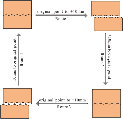
FIGURE 3. Route divisions of a single shear cycle (Qu 2018; Dong et al., 2020).
2.2 Deterioration in shear strength
2.2.1 Analyses of shear stress-displacement curves
As shown in Figure 4, in route 1 of cycle 1, the shear stress-displacement curve of the joint surface is mainly a peak curve, which indicates that the joint surface primarily undergoes shear failure. In the subsequent shear process, the shear stress-displacement curve of the joint surface is a slip curve, and the shear stress remains unchanged. This is because the slip and wear damage between the contact surface, cutting filling, and cuttings is the major cause of the subsequent shearing process. The deterioration in the shear strength of the joint surface under cyclic shear was mostly reflected in the first cyclic shear. Furthermore, as the normal stress increased, the slope of the elastic deformation stage increased before the shear stress reached its peak value (when the shear modulus increased). After the peak value, the rate of decrease in shear stress also increased, thus indicating that the shear failure characteristics of the joint surface become increasingly evident as the normal stress increases.
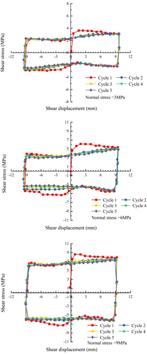
FIGURE 4. Shear stress-displacement curve of the structural plane under different normal stresses (Qu 2018; Dong et al., 2020).
2.2.2 Analyses of normal displacement-shear displacement curves
The normal displacement-shear displacement curves are shown in Figure 5, where the normal stress increases, maximum normal dilatancy displacement decreases, and shear shrinkage displacement increases. This is because as normal stress increases, the initial shear failure (especially in route 1) in the shear process of the joint surface becomes increasingly evident, and the degree of wear gradually intensifies in the subsequent shearing process, resulting in smaller particles, reduced volume, and lower filling height of the rock debris. In addition, following an increase in shear time, the lower the normal stress, the higher the overlap of the normal-shear displacement curves. This is because as the number of cyclic shear cycles increases, the degree of wear of the joint surface in each shearing process decreases. After multiple cyclic shears, the joint surface wear is gradually stabilised. Therefore, the lower the normal stress, the sooner the joint surface wear stabilises.
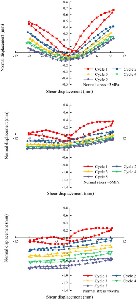
FIGURE 5. Normal displacement-shear displacement curve of the structural plane under different normal stresses (Qu 2018; Dong et al., 2020).
2.2.3 Deterioration of shear strength with an increase in cyclic shear times
Liu et al. (2011); Liu et al. (2013) defined the shear strength ratio of the joint surface. The joint surface shear strength ratio (Dn, ranging between 0.0 and 1.0) refers to the ratio of the peak shear strength of the n-th shear cycle (
The closer
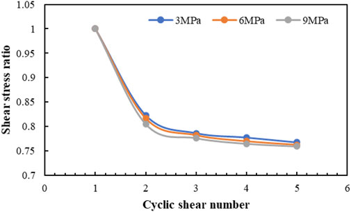
FIGURE 6. Change in shear strength ratio of the structural plane with cyclic shear times under different normal stress levels.
3 Shear strength of the rock mass joint surface under cyclic shear
The mechanism of the joint surface in the shearing process is relatively complex, and several factors contribute to its shear strength. For ordinary joint surface shear tests (without considering cyclic shear), the relationship curve between the shear stress and the normal stress of the joint surface is shown in Figure 7. In the initial stage of shearing, the joint surface mainly exhibits dilation, and as normal and shear stresses increase, part of the protrusions on the joint surface is sheared off until the plane reaches the peak strength. For the shear strength of the joint surface, Newland and Allely (1957) developed the following equation:
where
where
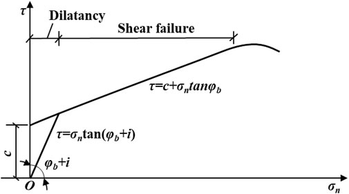
FIGURE 7. Relationship curve between the shear stress and normal stress of the structural plane (without considering cyclic shear).
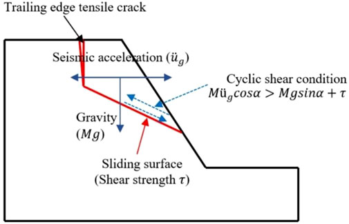
According to the test results, the shear failure of the joint surface occurs primarily in route 1 of cycle 1, and the cohesion force (c) should only be considered prior to the first shear process. Dong et al. (2020) proposed that in the analysis of slope stability under seismic loads, when the upward component of the horizontal seismic force (
where
where
Furthermore, Eq. 3 can be expressed as follows.
where
According to Eq. 5, when the normal stress and shear rate are constant, the shear stress is mainly affected by the undulant and basic friction angles. Therefore, clarifying the changes in the undulant angle and basic friction angle in the cyclic shear process is essential to determining the shear strength of the joint surface in the process of cyclic shear.
4 Deterioration of internal friction angle
4.1 Undulant angle of the joint surface
The surface morphology of the joint surface is a crucial factor affecting the shear failure mode, which can be explained by a study of the relationship between the undulant joint surfaces and strength. For a rock mass joint surface under a particular normal stress, the increase in the tangential displacement directly leads to a degradation of the undulant angle of the joint surface. When considering the degradation law of strength for rock mass joint surfaces under cyclic shear, the degradation phenomenon of its undulant angle during cyclic loading is typically considered. Pioneering research pertaining to the study of the degradation in the joint surface undulant angle was conducted by Plesha (1987), who proposed that the joint surface undulant angle
where
4.1.1 Damage coefficient of the joint surface
Hutson and Dowding (1990) and Jing et al. (1993) verified the accuracy of the model proposed by Plesha (1987). By fitting a large amount of experimental data, they further proposed the following empirical calculation formula for the damage coefficient c of the joint surface:
where
In Eq. 8, the JRC is the most difficult parameter to determine. Several methods, such as the roughness parameter, non-automatic continuous measurement, fractal dimension measurement, and empirical estimation methods, have been utilised to determine the JRC of rock masses. Although the roughness parameter method exhibits high measurement accuracy, measuring a joint surface contour curve is burdensome, which is not conducive to the rapid application of the model. Moreover, non-automatic continuous measurement may lead to large errors, thereby significantly reducing accuracy. The results of practical applications indicate that the steps for estimating JRC using fractal dimension measurement methods are cumbersome and slow. Barton and Choubey (1977) presented a set of ten increasing rough joint profiles measured on 10 cm long specimens based on a large number of tests, which can be physically compared with profiles measured on other joints (Figure 9). The method proposed by Barton and Choubey (1977) has been accepted by ISRM as a standard; however, its evaluation accuracy depends on the user’s experience and numerous subjective factors. A more reliable method for determining the JRC is conducting a tilt test on a jointed core. Based on the back-analysis and estimation of the results of several shear tests, Barton (1982) proposed the following equation:
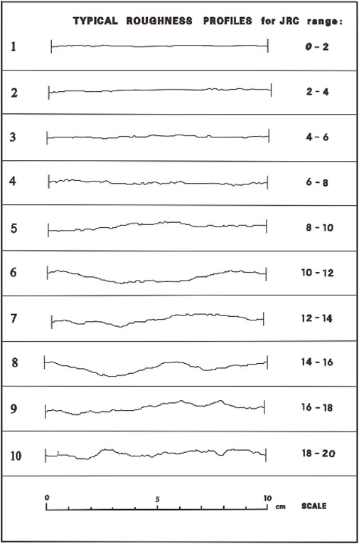
FIGURE 9. Rough joint Profliles (Barton and Choubey,1977).
According to Eq. 3, for the cyclic shear,
Then, Eq. 10 can be expressed as follows
where
4.1.2 Plastic work
In cyclic loading, the tangential displacement increment produced by cyclic loading can be expressed as
Furthermore, the cumulative tangential plastic work produced by the joint surface after n cyclic loadings is as follows:
Where
4.2 Basic friction angle of the joint surface
After n cycles, if the undulation angle of the joint surface is relatively close to its initial value, the deterioration degree of the joint surface is relatively low, indicating that the basic friction angle is also relatively close to its initial value. If the difference between the undulation angle after the n-th cyclic shear and the initial undulation angle is relatively close to the residual undulation angle (final undulation angle of the joint surface after the cyclic shear test), the degree of deterioration of the structural surface is relatively high, which implies that the basic friction angle is relatively close to the residual value. The change in the basic friction angle of the n-th cyclic shear
where
Therefore, the basic friction angle
The
where
Based on Eq. 4, the residual basic friction angle is expressed as follows
Furthermore, based on Eqs 21, 23, the basic friction angle can be determined as follows
5 Case study
5.1 Verification and improvement of the proposed method
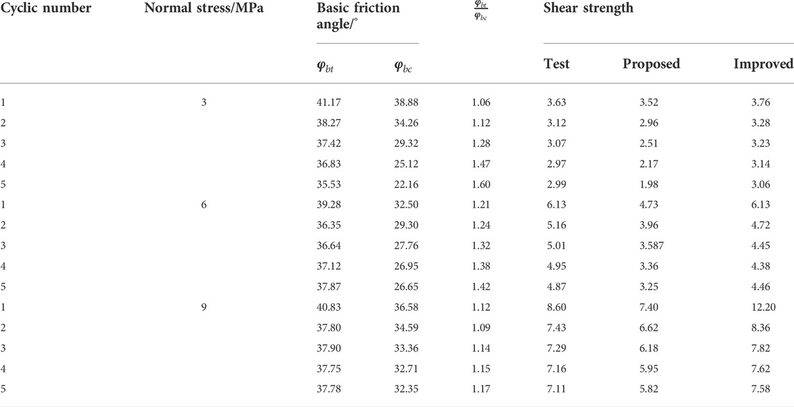
The feasibility of the proposed method was verified using the cyclic shear test results obtained by Qu (2018) (details are presented in Section 2). The cyclic shear tests and calculation results are presented in Figure 10 and Table 2. The calculation results of the proposed method are generally lower than the experimental values. This is because the calculation method is proposed considering the ideal state, that is, without considering the effect of cuttings on the shear strength of the joint surface during the cyclic shearing process. In fact, during the shearing process, the sheared cuttings are stuffed between the joint surfaces as fillers, causing the friction in the joint surface in the subsequent shear process, mainly generated in three parts: between two joint surfaces, between the joint surface and cuttings, and between the two sets of cuttings. The calculation results show that when calculating the cyclic shear strength of the joint surface, the influence of rock debris filling on the shear strength (especially the basic friction angle) of the joint surface must be considered.
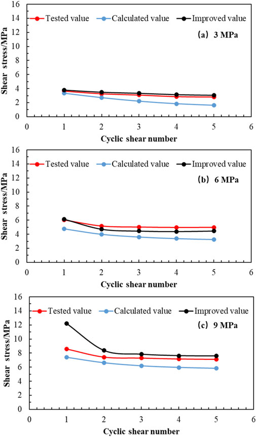
FIGURE 10. Shear stresses obtained by tests, proposed method, and improved method under different normal stress of 3, 6 and 9 Mpa.
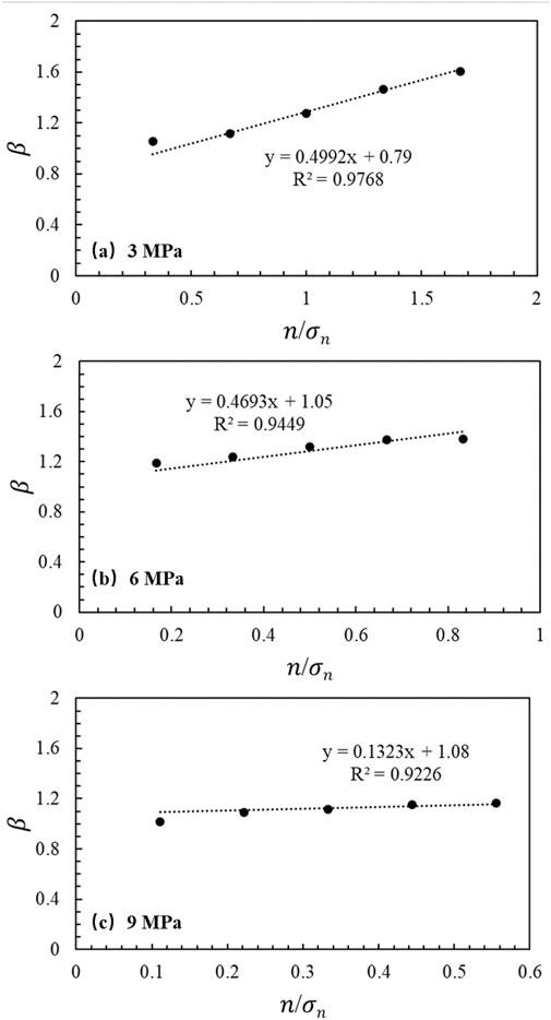
Therefore, it is necessary to improve the calculation method for the basic friction angle. A correction coefficient (β) was introduced to improve the accuracy of the basic friction angle. The correction coefficient is defined as the ratio of the basic friction angle obtained from the test to the calculated value:
where
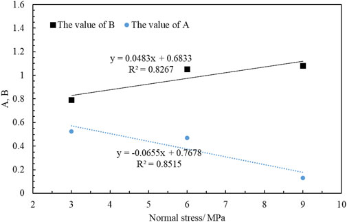
The values of A and B of the joint surface samples with the same intact rock strength have a linear relationship with the normal stress; therefore, the calculation formulas of parameters A and B are assumed to be as follows
where a, b, c, and d are constants. Finally, according to the fitting (Figure 12), A and B are obtained as follows:
Therefore,
The basic friction angle under the cyclic angle can be calculated as follows.
where
5.2 Comparative analysis
Comparison between the shear stress obtained using the proposed method, improved method, and tests is shown in Figure 10. The results show that regardless of the method, the shear strength of the joint surface decreases gradually as the number of cycles increases, and that the decreasing trend gradually slows down. Compared with the proposed method, the shear stress obtained using the improved method is in good agreement with the experimental results; however, when the normal stress was 9 MPa, the shear strength in cycle 1 was considerably different from the experimental value. The failure mode of the joint surface in cycle 1 under high normal stress conditions differed from that under low normal stress conditions. Under high normal stress, the failure mode of the protrusion was tensile rather than shear, and the tensile strength of the material was the controlling factor, which is inconsistent with the assumption that the matrix material reaches shear strength and fails made in the calculation equation. Therefore, when using the calculation equation to estimate the shear strength of the joint surface in cycle 1, the normal stress should not be too large.
6 Conclusion
This study investigated the shear strength of a rock mass joint surface under cyclic loading by first examining the effect of cyclic shear deterioration, the influence of vibration degradation in rock mass on the structural surface, undulant angle equation of the joint surface, and calculation method for the basic friction angle under a cyclic shearing load are proposed firstly. And then proposing an equation for calculating the shear strength, with the following conclusions:
1) Under the action of different normal stresses, as the number of cyclic shear cycles increases, the degree of wear of the joint surface in each shearing process decreases. After multiple cyclic shears, the joint surface gradually stabilises. The lower the normal stress, the sooner the joint surface wear stabilises.
2) During the shearing process, the sheared cuttings are stuffed between the joint surfaces, and the influence of the cutting and filling (produced in the shearing process) on the shear strength of the joint surface cannot be disregarded.
3) The improved model proposed in this study is in good agreement with the experimental results; however, when the improved proposed method is used to estimate the cyclic shear strength of the joint surface where the normal stress is too large, there may be errors in the calculation results.
Data availability statement
The original contributions presented in the study are included in the article/Supplementary Material, further inquiries can be directed to the corresponding author.
Author contributions
GH and JB were responsible for writing and idea discussions; Other authors were responsible for the editing of drawings, tables, and paper language.
Acknowledgments
Thank Shan Dong et al. (2020) for providing relevant data support.
Conflict of interest
The authors declare that the research was conducted in the absence of any commercial or financial relationships that could be construed as a potential conflict of interest.
Publisher’s note
All claims expressed in this article are solely those of the authors and do not necessarily represent those of their affiliated organizations, or those of the publisher, the editors and the reviewers. Any product that may be evaluated in this article, or claim that may be made by its manufacturer, is not guaranteed or endorsed by the publisher.
References
Atapour, H., and Moosavi, M. (2014). The influence of shearing velocity on shear behavior of artificial joints. Rock Mech. Rock Eng. 47 (5), 1745–1761. doi:10.1007/s00603-013-0481-9
Barla, G., Barla, M., and Martinotti, M. E. (2010). Development of a new direct shear testing apparatus. Rock Mech. Rock Eng. 43 (1), 117–122. doi:10.1007/s00603-009-0041-5
Barton, N. (1982). Modelling rock joint behavior from in situ block tests: Implications for nuclear waste repository design. Columbus, OH: Office of Nuclear Waste Isolation, 96. ONWI-308.
Barton, N. R., and Choubey, V. (1977). The shear strength of rock joints in theory and practice. Rock Mech. 10 (1), 1–54. doi:10.1007/bf01261801
Barton, N. (2020). The many faces of q-rock mass characterization for tunnels, caverns, slopes, tbm prognosis, deformability, shear strength, seismic velocity, permeability.
Bhasin, R., Kaynia, A., Blikra, L. H., Braathen, A., and Anda, E. (2004). Insights into the deformation mechanisms of a jointed rock slope subjected to dynamic loading. Int. J. Rock Mech. Min. Sci. (1997). 41 (3), 587–592. doi:10.1016/j.ijrmms.2004.03.104
Chen, Q., Liu, Y., and Pu, S. (2020). Strength characteristics of nonpenetrating joint rock mass under different shear conditions. Adv. Civ. Eng. 2020 (7), 1–13. doi:10.1155/2020/3579725
Cui, P., Su, Z. M., Chen, X. Q., and Zhou, J. W. (2013). formation and risk reduction of landslide-dammed lakes resulted by the ms 8.0 wenchuan earthquake: A brief review and a proposal. Springer Berlin Heidelberg.
Cui, S., Pei, X., Jiang, Y., Wang, G., Fan, X., Yang, Q., et al. (2021). Liquefaction within a bedding fault: Understanding the initiation and movement of the Daguangbao landslide triggered by the 2008 Wenchuan Earthquake (Ms = 8.0). Eng. Geol. 295, 106455. doi:10.1016/j.enggeo.2021.106455
Divoux, P., Boulon, M., and Bourdarot, E. (1997). A mechanical constitutive model for rock and concrete joints under cyclic loading. Proc. Damage Fail. Interfaces, 443–450.
Dong, S., Feng, W., Yin, Y., Hu, R., and Zhang, G. (2020). Calculating the permanent displacement of a rock slope based on the shear characteristics of a structural plane under cyclic loading. Rock Mech. Rock Eng. (53), 4583–4598. doi:10.1007/s00603-020-02188-y
Fathi, A., Moradian, Z., Rivard, P., and Ballivy, G. (2016). Shear mechanism of rock joints under pre-peak cyclic loading condition. Int. J. Rock Mech. Min. Sci. 83, 197–210. doi:10.1016/j.ijrmms.2016.01.009
Fox, D. J., Kan, D. D., and Hsiung, S. M. (1998). Influence of interface roughness on dynamic shear behavior in jointed rock. Int. J. Rock Mech. Min. Sci. 35 (7), 923–940. doi:10.1016/s0148-9062(98)00153-3
Fw, A., Jie, W. B., Han, B. C., Bo, L. A., Zs, D., and Dk, E. (2021). Advances in statistical mechanics of rock masses and its engineering applications. J. Rock Mech. Geotechnical Eng. 13 (1), 22–45. doi:10.1016/j.jrmge.2020.11.003
Goldstein, M., Goosev, B., Pvrogovsky, N., Tulinov, R., and Turovskaya, A. (1966). Investigation of mechanical properties of cracked rock. Surf. Rev. Lett. 7 (7), 667–671.
Han, D., Leung, Y. F., and Zhu, J. (2022). Tensile strength and deformational behavior of stylolites and mineral healed joints subject to dynamic direct tension. Rock Mech. Rock Eng. 55 (4), 1997–2009. doi:10.1007/s00603-021-02730-6
Homand, F., Belem, T., and Souley, M. (2001). Friction and degradation of rock joint surfaces under shear loads. Int. J. Numer. Anal. Methods Geomech. 25 (10), 973–999. doi:10.1002/nag.163
Hu, J., Li, S., Liu, H., Li, L., and Qin, C. (2020). New modified model for estimating the peak shear strength of rock mass containing nonconsecutive joint based on a simulated experiment. Int. J. Geomech. 20 (7), 04020091. doi:10.1061/(asce)gm.1943-5622.0001732
Huang, R., and Li, W. (2009). Development and distribution of geohazards triggered by the 5.12 Wenchuan Earthquake in China. Sci. China Ser. E-Technol. Sci. 52 (4), 810–819. doi:10.1007/s11431-009-0117-1
Huang, X., Haimson, B. C., Plesha, M. E., and Qiu, X. (1993). An investigation of the mechanics of rock joints-Part I. Laboratory investigation. Int. J. Rock Mech. Min. Sci. Geomechanics Abstr. 30 (3), 257–269. doi:10.1016/0148-9062(93)92729-a
Hutson, R. W., and Dowding, C. H. (1990). Joint asperity degradation during cyclic shear. Int. J. Rock Mech. Min. Sci. Geomechanics Abstr. 27 (2), 109–119. doi:10.1016/0148-9062(90)94859-r
Jafari, M. K., Hosseini, K. A., Pellet, F., Boulon, M., and Buzzi, O. (2003). Evaluation of shear strength of rock joints subjected to cyclic loading. Soil Dyn. Earthq. Eng. 23 (7), 619–630. doi:10.1016/s0267-7261(03)00063-0
Jing, L., Stephansson, O., and Nordlund, E. (1993). Study of rock joints under cyclic loading conditions. Rock Mech. Rock Eng. 26 (3), 215–232. doi:10.1007/bf01040116
Lee, H. S., Park, Y. J., Cho, T. F., and You, K. H. (2001). Influence of asperity degradation on the mechanical behavior of rough rock joints under cyclic shear loading. Int. J. Rock Mech. Min. Sci. (1997). 38 (7), 967–980. doi:10.1016/s1365-1609(01)00060-0
Li, H. (2022). SCADA data based wind power interval prediction using LUBE-based deep residual networks. Front. Energy Res. 10, 920837. doi:10.3389/fenrg.2022.920837
Li, H. (2022). Short-term wind power prediction via spatial temporal analysis and deep residual networks. Front. Energy Res. 10, 920407. doi:10.3389/fenrg.2022.920407
Li, H., Deng, J., Feng, P., Pu, C., Arachchige, D., and Cheng, Q. (2021). Short-term nacelle orientation forecasting using bilinear transformation and ICEEMDAN framework. Front. Energy Res. 9, 780928. doi:10.3389/fenrg.2021.780928
Li, H., Deng, J., Yuan, S., Feng, P., and Arachchige, D. (2021). Monitoring and identifying wind turbine generator bearing faults using deep belief network and EWMA control charts. Front. Energy Res. 9, 799039. doi:10.3389/fenrg.2021.799039
Liu, B., Li, H., Liu, Y., and Xia, X. (2013). Generalized damage model for asperity and shear strength calculation of joints under cyclic shear loading. Chin. J. Rock Mech. Eng. 32 (2), 3000–3008.
Liu, B., Li, H., and Zhu, X. (2011). Experiment simulation study of strength of degradation of rock joints under cyclic shear loading. Chin. J. Rock Mech. Eng. 30 (10), 2033–2039.
Liu, Y. (2017). Study on cumulative damage evolution mechanism and stability of bedding rock slope in reservoir area under frequent microseismic. Chongqing: Chongqing University.
Mirzaghorbanali, A., Nemcik, J., and Aziz, N. (2014). Effects of shear rate on cyclic loading shear behaviour of rock joints under constant normal stiffness conditions. Rock Mech. Rock Eng. 47 (5), 1931–1938. doi:10.1007/s00603-013-0453-0
Moriya, H., Abe, S., Ogita, S., and Higaki, D. (2010). Structure of the large-scale landslide at the upstream area of aratozawa dam induced by the iwate-miyagi nairiku earthquake in 2008. J. Jpn. Landslide Soc. 47 (2), 77–83. doi:10.3313/jls.47.77
Mroz, Z., and Giambanco, G. (2015). An interface model for analysis of deformation behaviour of discontinuities. Int. J. Numer. Anal. Methods Geomech. 20 (1), 1–33. doi:10.1002/(sici)1096-9853(199601)20:1<1::aid-nag799>3.0.co;2-l
Newland, P. L., and Allely, B. H. (1957). Volume changes in drained taixial tests on granular materials. Geotechnique 7 (1), 17–34. doi:10.1680/geot.1957.7.1.17
Patton, F. D. (1966b). Multiple modes of shear failure in rock. Proceeding the1st Congr. Int. Soc. Rock Mech. 1, 509–513.
Patton, F. D. (1966a). Multiple modes of shear failure in rock and related materials. Illinois: University of Illinois.
Plesha, M. E. (1987). Constitutive models for rock discontinuities with dilatancy and surface degradation. Int. J. Numer. Anal. Methods Geomech. 11 (4), 345–362. doi:10.1002/nag.1610110404
Premadasa, W., Indraratna, B., Mizargobanali, A., and Oliveira, D. (2012). Shear behaviour of rock joints under cyclic loading. Australia-New Zealand conference on geomechanics: Ground engineering in A changing world.
Qiu, X., Plesha, M., Huang, X., and Haimson, B. (1993). An investigation of the mechanics of rock joints-Part II. Analytical investigation. Int. J. Rock Mech. Min. Sci. Geomechanics Abstr. 30 (3), 271–287. doi:10.1016/0148-9062(93)92730-e
Qu, J. (2018). Experimental study on shear characteristics of rock joints under cyclic loading. Dissertation: Chongqing University.
Siad, L. (2003). Seismic stability analysis of fractured rock slopes by yield design theory. Soil Dyn. Earthq. Eng. 23 (3), 21–30. doi:10.1016/s0267-7261(02)00213-0
Wang, S., and Zhang, J. (1982). Dynamic analysis of sliding stability of slope rock mass. Chin J Geol 2, 162–170.
Woo, I., Fleurisson, J. A., and Park, H. J. (2010). Influence of weathering on shear strength of joints in a porphyritic granite rock mass in Jechon area, South Korea. Geosci. J. 14 (3), 289–299. doi:10.1007/s12303-010-0026-0
Xia, C., Song, Y., Tang, Z., and Shou, C. (2012). Particle flow numerical simulation for shear behavior of rough joints. Chin. J. Rock Mech. Eng. 31 (8), 1545–1552.
Xie, S., Lin, H., Cheng, C., Chen, Y., Wang, Y., Zhao, Y., et al. (2022). Shear strength model of joints based on Gaussian smoothing method and macro-micro roughness. Comput. Geotechnics 143, 104605. doi:10.1016/j.compgeo.2021.104605
Xu, J., Liu, Y., Yin, G., Li, B., and Ye, G. (2015). Development of shear-flow coupling test device for coal rock. Chin. J. Rock Mech. Eng. 34, 2987–2995.
Zhang, X., Ren, M., Meng, Z., Zhang, B., and Li, J. (2021). Experimental study on the mechanical behavior of yunnan limestone in natural and saturated states. Adv. Civ. Eng., 1–16. doi:10.1155/2021/6614412
Keywords: degradation effect, undulant angle, basic friction angle, shear strength, joint surface
Citation: Hu G, Wang L, Bai J, Ma S and Tang Y (2022) Calculating the shear strength of a rock mass joint surface considering cyclic shear deterioration. Front. Earth Sci. 10:960677. doi: 10.3389/feart.2022.960677
Received: 03 June 2022; Accepted: 30 June 2022;
Published: 26 July 2022.
Edited by:
Jingren Zhou, Sichuan University, ChinaReviewed by:
Yunfeng Zhou, Universitat Politecnica de Catalunya, SpainYang Lu, Hohai University, China
Copyright © 2022 Hu, Wang, Bai, Ma and Tang. This is an open-access article distributed under the terms of the Creative Commons Attribution License (CC BY). The use, distribution or reproduction in other forums is permitted, provided the original author(s) and the copyright owner(s) are credited and that the original publication in this journal is cited, in accordance with accepted academic practice. No use, distribution or reproduction is permitted which does not comply with these terms.
*Correspondence: Guangzhong Hu, aGd6c3MxOTgzQDE2My5jb20=
 Guangzhong Hu
 Lijuan Wang3